Roadefend RDT600 User manual

Installation
Instruction
RDT600 Proactive AI Safety System

RDT600 Installation Instruction Ver.1.1
1
Revision History:
Version
Number
Revised By
Revision Date
Revision Description
V1.0
Xu Zhiwu
2023.04.24
<1> First draft of integrated
release
V1.1
Xu Zhiwu
2023.06.25
<1> Update some images in the
instructions section of the web
side configuration tool

RDT600 Installation Instruction Ver.1.1
2
Table of contents
1. Overview........................................................................................................................................................................... 4
2. Product Configuration....................................................................................................................................................... 4
2.1 Product standard packing list ............................................................................................................................... 4
2.1.1 The standard package is as follows:......................................................................................................... 4
2.2 Product optional accessories list .......................................................................................................................... 5
2.3 Equipment Harness............................................................................................................................................... 5
2.3.1 Power harness.......................................................................................................................................... 5
2.3.2 4- core IO communication harness ( optional)......................................................................................... 6
2.3.3 8- core IO communication harness (optional).......................................................................................... 7
2.3.4 Aviation head interface camera adapter cable ......................................................................................... 7
3. Preliminary preparation.................................................................................................................................................... 8
3.1 Site condition preparation.................................................................................................................................... 8
3.1.1 Site terrain requirements.......................................................................................................................... 8
3.1.2 Installer Requirements ............................................................................................................................. 9
3.1.3 Vehicle information confirmation............................................................................................................ 9
3.2 Installation Tool List.............................................................................................................................................. 9
3.3 Device information confirmation........................................................................................................................ 10
3.3.1 Hardware information confirmation ...................................................................................................... 10
3.3.2 Software information confirmation........................................................................................................ 11
4. Installation Notes............................................................................................................................................................ 11
4.1 Equipment and wiring harness docking.............................................................................................................. 11
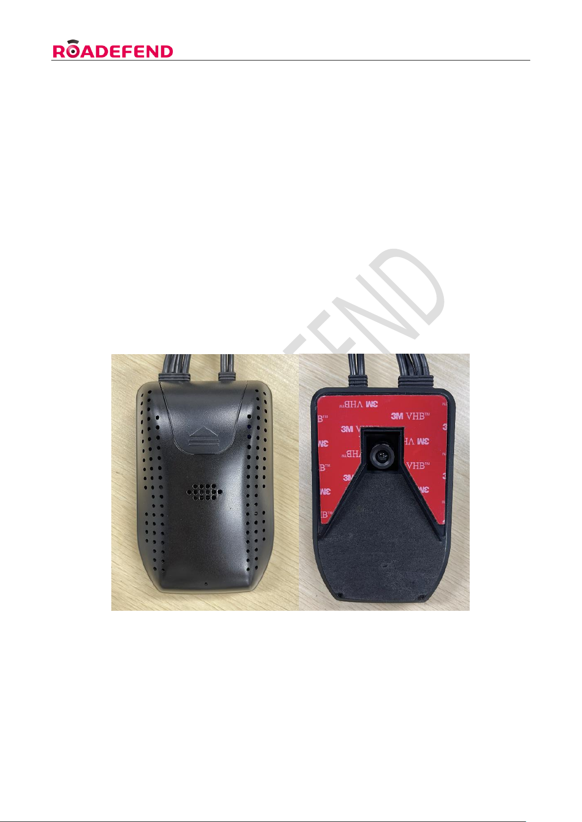
4.1.1 Host front and back view....................................................................................................................... 11
4.1.2 Host side view........................................................................................................................................ 11
4.1.3 System connection diagram................................................................................................................... 12
4.2 Equipment and wiring harness docking.............................................................................................................. 12
4.2.1 Installation location requirements.......................................................................................................... 13
4.2.2 Host wiring ............................................................................................................................................ 13
4.2.3 ADAS camera debugging ...................................................................................................................... 14
4.3 DMS camera installation and debugging ............................................................................................................ 15
4.3.1 Installation location requirements.......................................................................................................... 15
4.3.2 Installation steps .................................................................................................................................... 15
4.3.3 Routing and precautions ........................................................................................................................ 16
4.4 GPS antenna installation..................................................................................................................................... 16
4.5 Storage media and IoT card installation ( picture) ............................................................................................ 17
5. Use of web-side configuration tools ............................................................................................................................... 17
5.1 Login.................................................................................................................................................................... 17
5.1.1 Connect to WIFI hotspot........................................................................................................................ 17
5.1.2 Log in to the web tool............................................................................................................................ 18
5.2 Status query........................................................................................................................................................ 18

RDT600 Installation Instruction Ver.1.1
3
5.3 Parameter setting ............................................................................................................................................... 19
5.3.1 Set vehicle information.......................................................................................................................... 19
5.3.2 Set switch value ..................................................................................................................................... 19
5.3.3 Mirror/Flip Settings ............................................................................................................................... 19
5.3.4 Test mode............................................................................................................................................... 19
5.4 ADAS calibration ................................................................................................................................................. 20
5.5 Live image ........................................................................................................................................................... 21
6. Notice to users................................................................................................................................................................ 22
RDT600 Installation Instruction Ver.1.1
4
1. Overview
This article introduces in detail the composition of the RDT600 active safety intelligent prevention and
control system , the installation standards and precautions of the host and its accessories . Provide
reference and guidance for on-site installation personnel , provide construction personnel with
installation operation requirements , standardize the installation and commissioning process , Improve
construction efficiency , Make sure the equipment is working properly .
2. Product Configuration
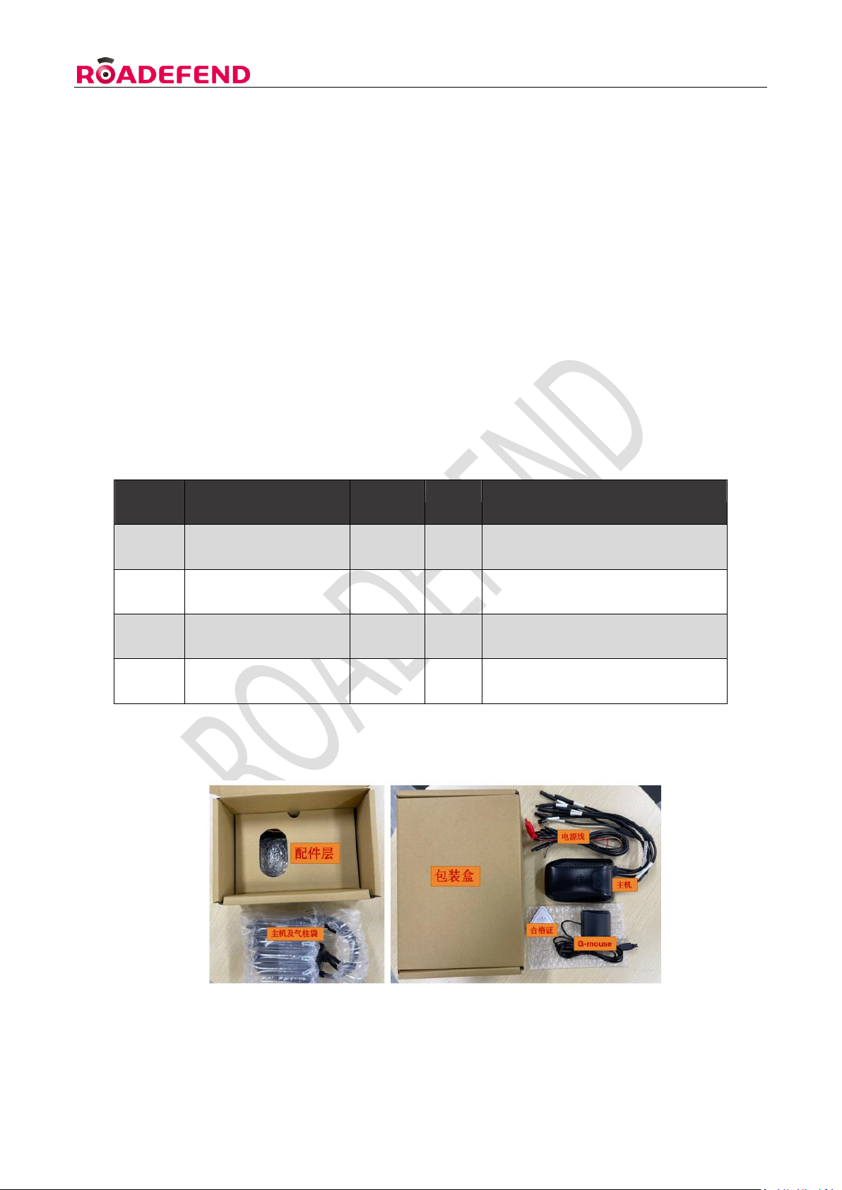
2.1 Product standard packing list
Table 1: Standard product packing list
2.1.1 The standard package is as follows:
Figure 1 : Product standard packaging diagram
Serial
Number
Name
Quantity
Unit
Remark
1
RDT600 host
1
tower
2
Power Cable
1
root
3
G-mouse
1
indivua
4
Triangle certificate
1
pieces
RDT600 Installation Instruction Ver.1.1
5
2.2 Product optional accessories list
Serial
Number
Name
Quantity
Unit
Remark
1
DMS Camera
1
indivual
Optional according to project
requirements
2
OMS Camera
1
indivual
Optional according to project
requirements
3
Aviation head interface
camera adapter cable
1-4
root
This adapter cable is required when
the camera interface is a 4-pin
aviation head
4
BSD camera
1-2
indivual
Optional according to project
requirements
5
4-core IO cable
1
root
Optional according to project
requirements
6
8 core IO cable
1
root
Optional according to project
requirements
7
TF card
1-2
open
Single card supports up to 512G
8
IoT card
1
open
Middle card
Table 2: Product selection list
2.3 Equipment Harness
The wiring harness has a variety of function combination options , please consult sales or technical
support for details.
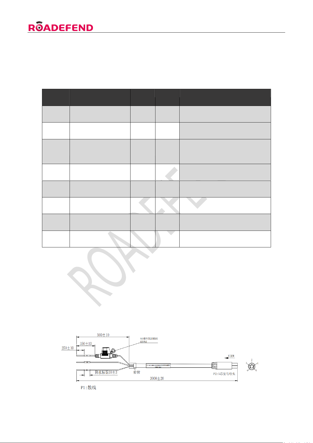
2.3.1 Power harness
RDT600 Installation Instruction Ver.1.1
6
Figure 2: Diagram of power harness
Table 3: Definition of harness pins
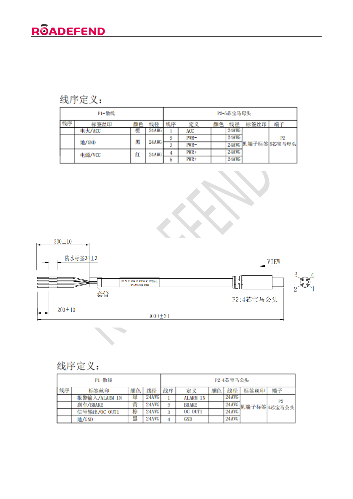
2.3.2 4- core IO communication harness ( optional)
Used to connect the body hardware line signal , Such as brakes , left/right turn signals , high/low
beams , CAN communication, etc. , for details, refer to the wiring harness definition.
Figure 3 4 -core IO communication line
Table 4 Pin definition of 4- core IO communication line

RDT600 Installation Instruction Ver.1.1
7
2.3.3 8- core IO communication harness (optional)
Figure 4 8- core IO communication line
Table 5: Pin definition of 8- core IO communication line
2.3.4 Aviation head interface camera adapter cable
For host and 4- core aerial camera

RDT600 Installation Instruction Ver.1.1
8
Picture 6 Aviation head interface camera adapter cable
3. Preliminary preparation
3.1 Site condition preparation
3.1.1 Site terrain requirements
Find an open area before installation . In principle, it is required to be on a flat road with a wide view
(you can see the skyline ) , Areas with lane lines for installation and calibration . Considering the actual
situation , At least install and calibrate on level ground .
Stop the vehicle horizontally , and it is forbidden to tilt the vehicle when the equipment is installed and
calibrated . There are two methods for specific site requirements :
Method 1 : Find a straight lane to ensure that the front view is wide and you can see the distant skyline .
Park the vehicle in the center of the long straight horizontal lane , and ensure that the vehicle stops
straight , as shown in the left picture below :
Method two : Find a flat open space , Make sure that the ground where the vehicle is parked is not
sloped .There is no less than 5 meters of open space in front of the installation site vehicle , which is
convenient for the installation personnel to calibrate , as shown in the right picture above :

RDT600 Installation Instruction Ver.1.1
9
3.1.2 Installer Requirements
On-site construction personnel should be familiar with the functions and applications of the product ,
understand the composition and working principle of the entire system , and be familiar with the internal
structure and electrical circuits of motor vehicles , etc. Have experience in the installation and
construction of common in-vehicle equipment . Need to know the installation location in advance ,
Know the vehicle model where the device is installed , Host and camera installation location selection,
Various cable lengths required for installation, Prepare the necessary auxiliary materials in advance,
Ensure the smooth completion of equipment installation and commissioning .
3.1.3 Vehicle information confirmation
Before the equipment is installed , On-site construction personnel must confirm the electrical
information of the vehicle . The step is vehicle damage (in case of occurrence ) .The basis for the
division of responsibilities involved , the following operations must be checked and correct before
proceeding to the next step of installation :
Whether the vehicle can ignite normally .
Whether the vehicle power system is intact , Whether there are other electrical faults, etc.
the vehicle has any external damage .
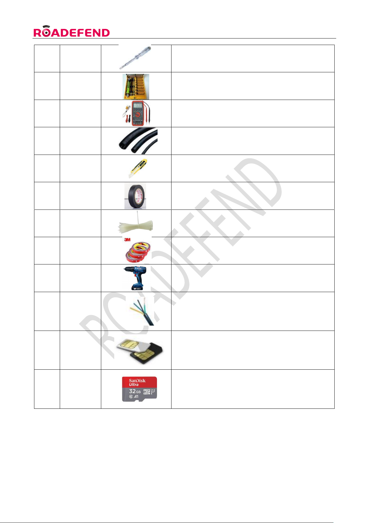
3.2 Installation Tool List
Serial
Number
Name
Real
Specification
1
Wire Stripper
Universal type for stripping and cutting lines
2
Tape
Measure
Exceed 5M
RDT600 Installation Instruction Ver.1.1
10
3
Electric Pen
Universal
4
Screwdriver
Set
Length greater than 20cm , with a cross and a cape
5
Multimeter
General purpose , for measuring voltage , left and
right turn signals , brake signal etc.
6
Bellows
2cm straight , Beautiful packaging for wiring , Prevent
leakage line damage
7
Utility Knife
Used for cutting corrugated pipes , rolling strips and
other items
8
Insulation
Black Tape
Universal type, for wrapping wire ends
9
Cable Ties
7cm long for fixing the harness
10
3M Glue
Universal type , used to fix the DMS base when drilling
is not possible
11
Electrical tools
For fixing screws , And opening holes when walking
dark lines
12
R v wire
Used to connect vehicle power lines , signal power
lines , and signals to equipment to extend the
function; Power wire diameter 1.5mm², Signal
wire diameter 0 . 5 mm ²
13
IoT card
IoT card - medium card (China Mobile , China Unicom
or China Telecom ) is used for communication
between devices and platforms
14
Storage
medium
Support 2 TF cards . It is used to store videos and
needs to be purchased in advance .
3.3 Device information confirmation
3.3.1 Hardware information confirmation
RDT600 Installation Instruction Ver.1.1
11
Before installation, check whether the equipment is complete and whether there is any damage , etc.
The specific equipment list is subject to the project plan .
3.3.2 Software information confirmation
Check the shipping information sheet before installation to confirm the correctness of the factory
version of the device software.If you find that the device software version is inconsistent with the
required version , you need to contact the person in charge immediately to check and deal with it .
Perform upgrade operations when necessary.Confirmation method : After the device is powered on,
check whether the firmware version information and patch number are consistent with the factory
shipment information through the web page .
4. Installation Notes
4.1 Equipment and wiring harness docking
4.1.1 Host front and back view
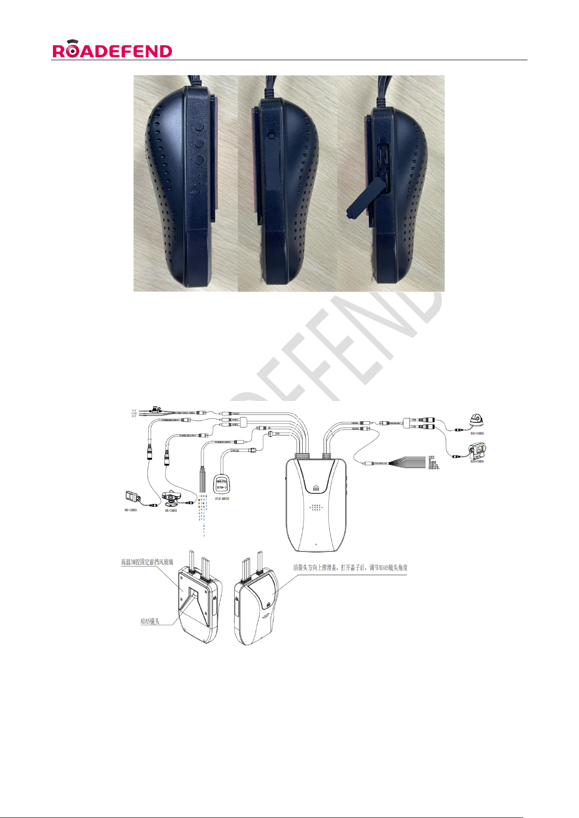
4.1.2 Host side view
RDT600 Installation Instruction Ver.1.1
12
4.1.3 System connection diagram
4.2 Equipment and wiring harness docking
RDT600 Installation Instruction Ver.1.1
13
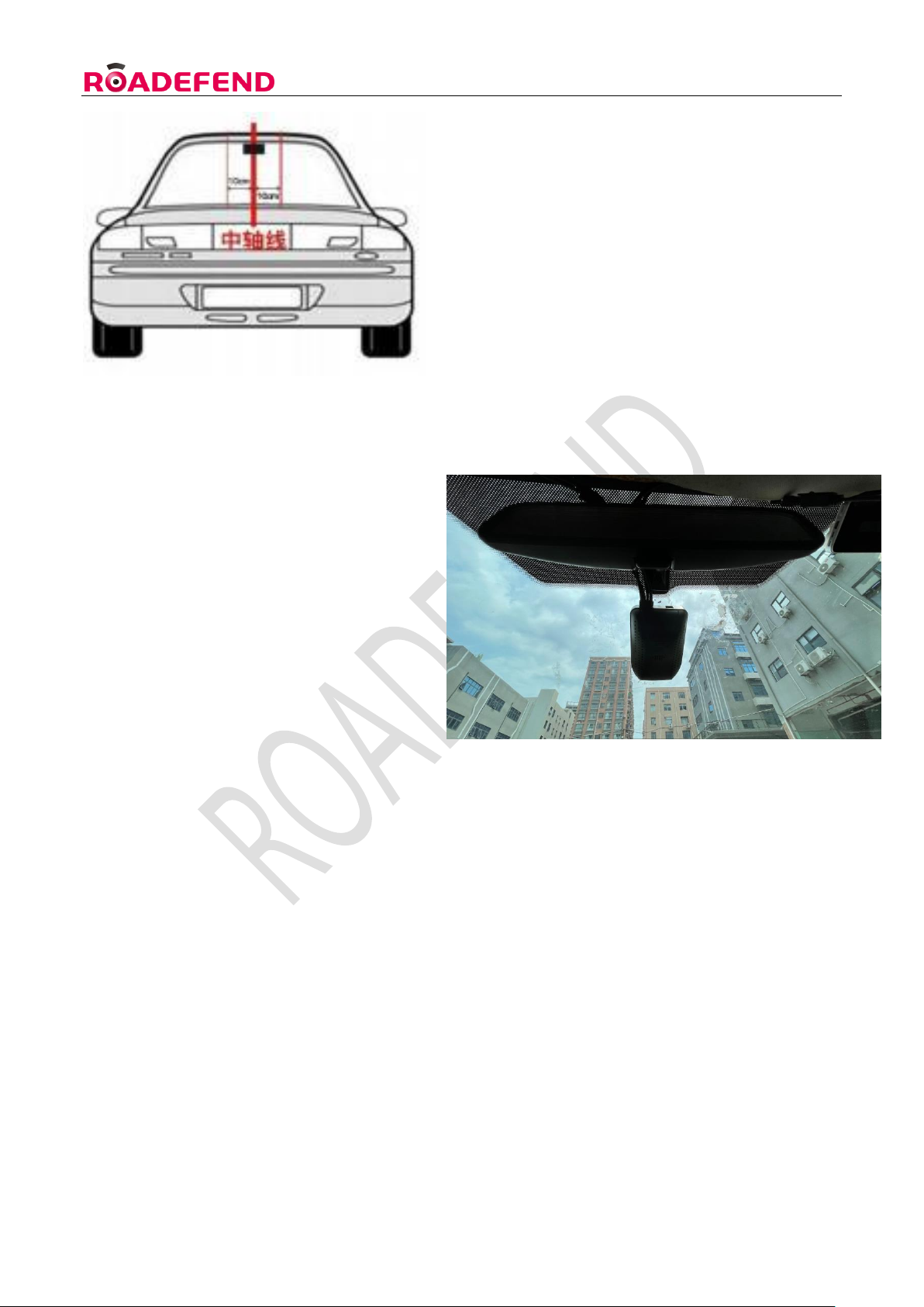
4.2.1 Installation location requirements
1). The host is fixed near the rearview mirror of the front windshield (the top function line is hidden in
the roof compartment), and it is as close as possible to the middle of the entire width of the windshield.
2). Before installing and fixing, ensure that the ADAS camera is horizontally illuminated on the road
surface and does not deviate from the straight line of the road. It is required to check whether there is
any potential risk of line damage or equipment failure on the vehicle at the selected location.
3). If there is a lens from another manufacturer occupying the position, use the "overlay method" to
install and fix it, and try to ensure that the lens is centered.
4). After determining the installation location of the host, wipe the windshield of the installation area
with cleaning paper to ensure that the relevant area is clean.
5). Take off the ADAS camera lens sticker, tear off the 3M adhesive sticker of the main unit and stick it
well.
6). After pasting the main unit, press it hard to make the main unit firmly stick to the glass, so as to
prevent the main unit from loosening or falling off.
4.2.2 Host wiring
The wiring of the equipment should be as dark as possible . Ensure that the operating table is clean
and beautiful ; The wiring harness exposed outside the cab ( if any) needs to be protected by corrugated
tubes , And need to avoid frequently moving parts , Prevent damage to the wire harness due to
vibration and pulling during use .
First find the body's constant power line (Vin) , car ignition switch line (ACC) , ground line (GND) , left
and right steering and brake signal lines . Usually available
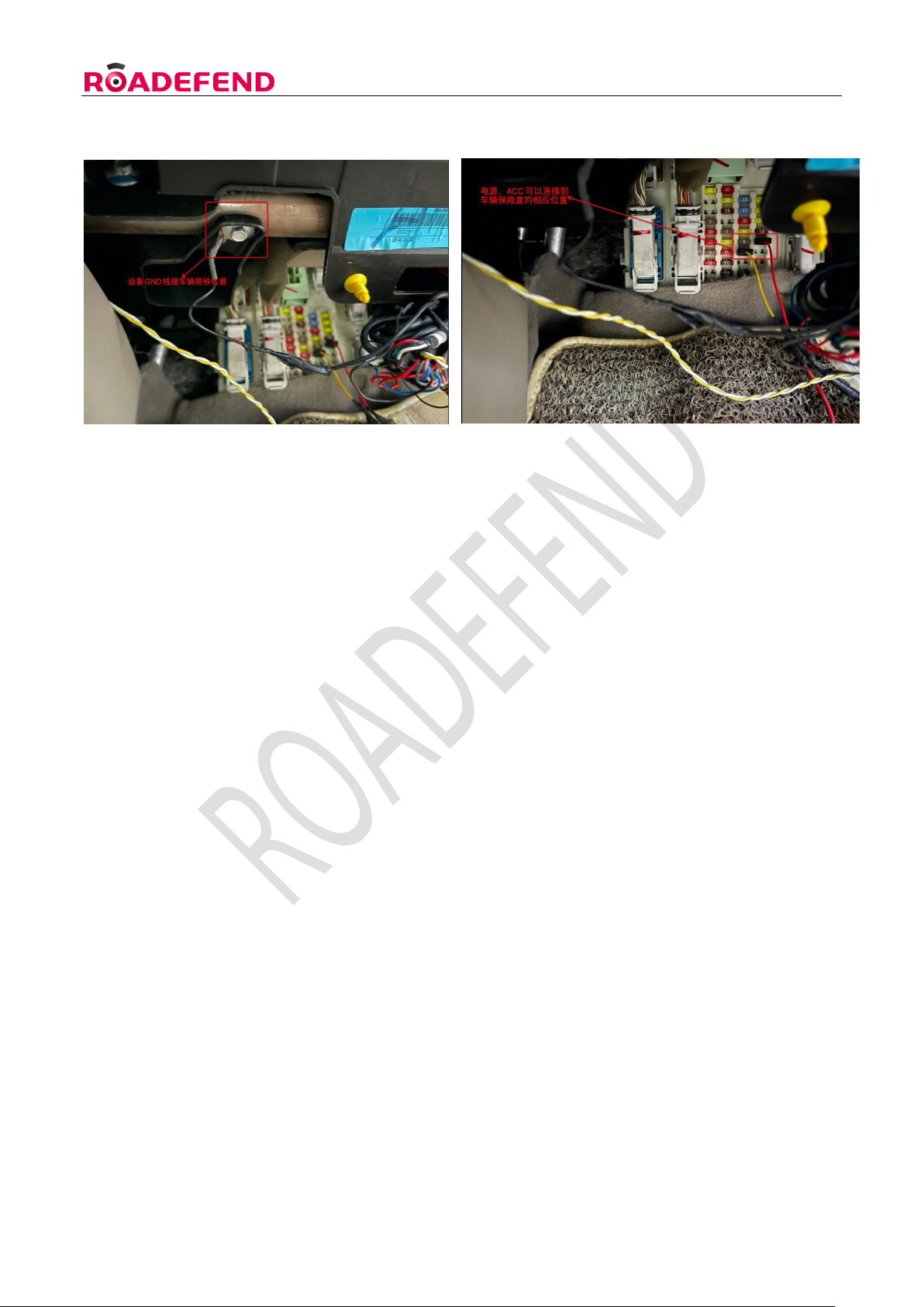
RDT600 Installation Instruction Ver.1.1
14
Find the corresponding wiring position through the instructions of the body fuse box , As shown below :
If the description of the fuse box is vague and cannot be judged , The corresponding wiring harness
can be found through the electric pen measurement method . The judgment method is as follows :
Normal power line (Vin ) : When the vehicle is turned off, use an electric pen to measure whether the
line has electricity . If there is electricity, it can be judged that the line is a normal power line , and then
measure the voltage , Make sure it is within the range of use of the device .
Ignition signal wire (ACC ) : Through electric pen measurement , if the line voltage is 0V , the line is
charged after the vehicle is ignited , then it can be judged that the line is the ignition signal line . Then
make a voltage measurement , Make sure the voltage is working properly .
Brake and left and right turn signal lines : Measured by electric pen , When the vehicle does not
turn on the left and right turn signals, the line has no voltage , There is voltage on the line when the
vehicle turns left and right . It means that the line is the left and right steering signal line ; The same
goes for the brakes . If the signal line cannot be determined through the above methods , Please
contact the team or other professional auto repair shop for assistance .
According to different customer needs , other unused wiring harnesses such as 485 communication wires ,
etc. , can not be connected if there is no requirement , but must be wrapped with insulating tape to
ensure that the exposed part of the wire does not contact any part of the vehicle body .
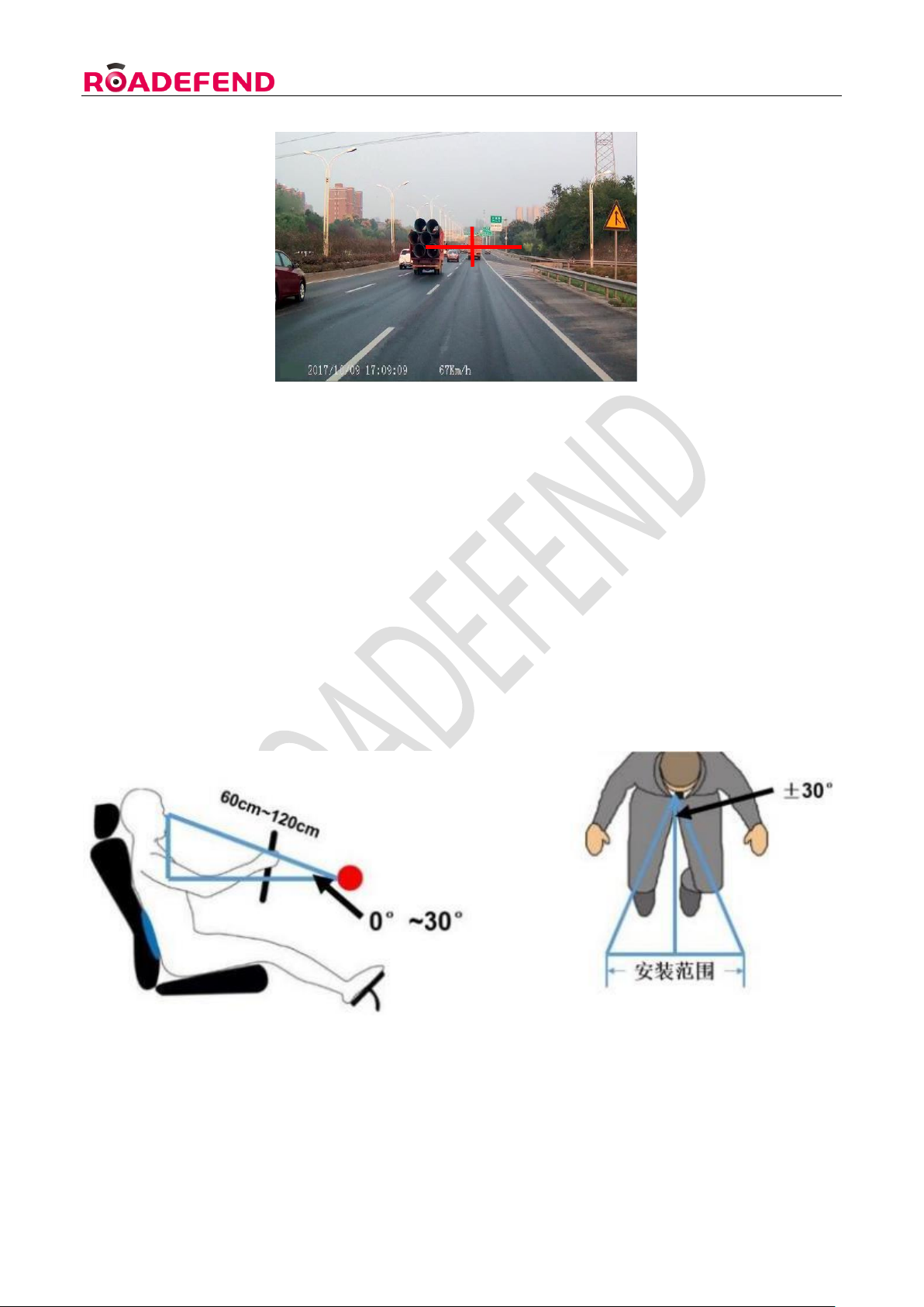
4.2.3 ADAS camera debugging
Open and log in the mobile APP , preview the real-time video of the ADAS channel, adjust the camera
angle so that the horizontal line of the cross star in the image is flush with the skyline of the road, and
the vertical line is flush with the center of the lane.
RDT600 Installation Instruction Ver.1.1
15
4.3 DMS camera installation and debugging
4.3.1 Installation location requirements
DMS The camera is installed in front of the driver , distance from driver's face 60cm~ 120cm range ,
The angle between the normal line of the face and the driver is required to be less than ±30° when
looking straight ahead ; the angle between the normal line of the face and the face in the vertical
direction is less than 30° , as shown in the figure below .
4.3.2 Installation steps
Step 1: According to the installation location requirements, find a suitable installation location on the

RDT600 Installation Instruction Ver.1.1
16
front windshield near the left A- pillar (you can power on the device first, and check the DMS video
screen through the mobile APP real-time video to confirm whether the installation location is suitable) ,
and use a paper towel Or clean the installation position with a dry towel, tear off the 3M adhesive
sticker on the base of the DMS camera , stick the base to the installation position on the windshield
and use a little force to make it stick firmly .
Step 2: When adjusting the angle, the installer needs to fasten the seat belt, open and log in the
mobile APP, preview the real-time video of the DMS channel, and adjust the camera angle so that the
driver's face is in the center of the screen as much as possible, as shown in the figure below (the
position inside the red dotted line box in the figure ):
4.3.3 Routing and precautions
Since the camera is installed in front of the drive, it must be
ensured that it will not block the driver's vision after installation .
In the camera image, it should be ensured that the steering wheel does not block the driver's face. If
there is a need for occlusion, the installation location needs to be changed .
The wiring of the equipment should try to ensure that the dark line is used.Ensure that the operating
table is clean and beautiful,Exposed wiring harnesses need to be protected by bellows,Prevent breakage
during later use .
4.4 GPS antenna installation
The installation position of the GPS antenna is preferably on the roof, and the wiring can be drilled into
the car through holes or along the door gap. If it cannot be installed on the roof, it is recommended to

RDT600 Installation Instruction Ver.1.1
17
install it on the console in front of the passenger seat, as close to the window as possible. The distance
from the electronic equipment is more than 50cm, pay attention to the receiving side of the antenna
facing up, and tear off the 3M adhesive protective film and stick it on the table to ensure that the antenna
is stable during driving. It is strictly forbidden to stick the GPS antenna on the equipment.
4.5 Storage media and IoT card installation ( picture)
5. Use of web-side
configuration tools
5.1 Login
5.1.1 Connect to WIFI hotspot
Open the WiFi connection interface on the mobile phone, and you can see the hotspot with the WiFi
name "RDT600-the last six digits of the device number", such as RDT600-000949,
Connect to this WiFi hotspot, the WiFi hotspot password of all RDT600 is uniform: 12345678, after the

RDT600 Installation Instruction Ver.1.1
18
connection is successful, go to the next step.
5.1.2 Log in to the web tool
Open the mobile browser, enter " 192.168.1.1 " in the URL bar , click Go, and enter the login page; After
verifying the consistency between the device number and the actual device number, enter the username
and password (please request from the manufacturer), click Login to enter the home page of the web
tool .
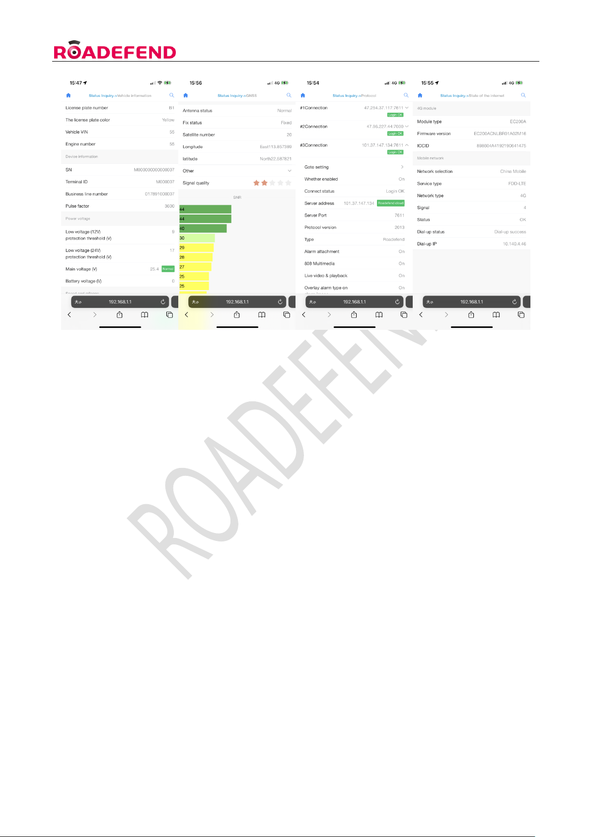
5.2 Status query
Click "Status Query" to enter the status query page. The status query includes: version information ,
vehicle information , storage , GPS , protocol , switching value status , networking status , etc.
RDT600 Installation Instruction Ver.1.1
19
5.3 Parameter setting
5.3.1 Set vehicle information
Click "Parameter Settings-General-Vehicle Information" to set the license plate number, license plate
color , etc. The online number can be clicked on the right " +"
Select "Freight" or "Default" (recommended to choose "Freight") or fill in according to your needs .
5.3.2 Set switch value
Click "Parameter Settings-General-Switch Volume", and set each switch volume to be active at high
level or low level according to the actual situation
5.3.3 Mirror/Flip Settings
According to actual project needs, click on "Parameter Settings-Video-Mirror Flip" to set the mirror/flip
settings for a certain channel screen.
5.3.4 Test mode
Click "Parameter Settings-Active Safety-Test Mode", the device enters the test mode, and can perform
Table of contents


