fadini Strabuc 918 User manual

I- Libretto di istruzioni
GB - Instructions manual
F- Notices de montage
Strabuc 918
EN 13241
EN 12453
EN 12445
made in Italy
the gate opener
Strabuc 930
GB Instructions Manual
pages 17 - 32
- 17 -

- 18 -
FOR OPTIMAL APPLICATION AND USE OF THE STRABUC 918 AND STRABUC 930 PLEASE READ THE INSTRUCTIONS AND CONSULT EXPLANATORY DIAGRAMS.
IMPORTANT: ALL INSTALLATION OPERATIONS MUST BE PERFORMED BY A QUALIFIED TECHNICIAN, IN OBSERVANCE OF THE EN 12453 - EN 12445 SAFETY REGULATIONS
AND MACHINERY DIRECTIVE 2006/42/CE.
CAREFUL RISK ANALYSIS IS REQUIRED UNDER APPLICABLE REGULATIONS.
GENERAL COMMENTS
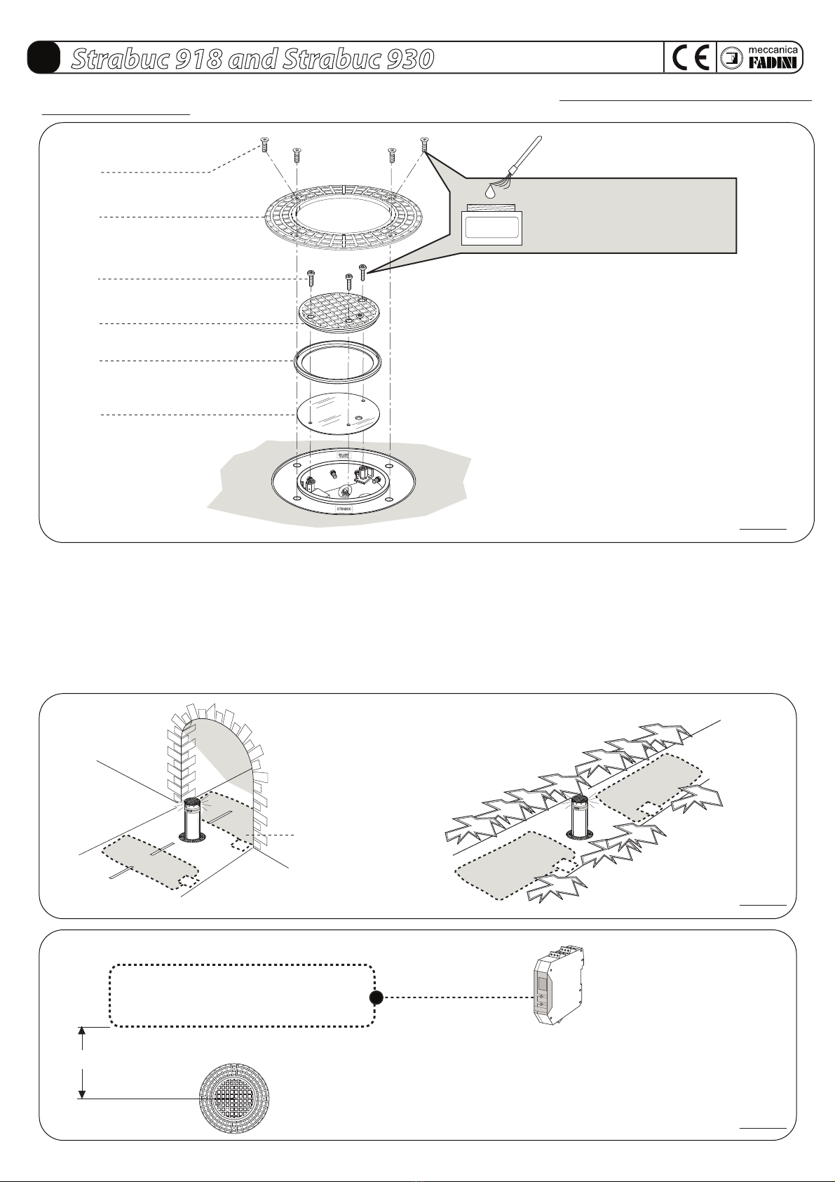
STRABUC 918 and STRABUC 930 are a fully retractable, belowground, oil-hydraulic steel trac control post intended to prevent unauthorised vehicular access. It is an
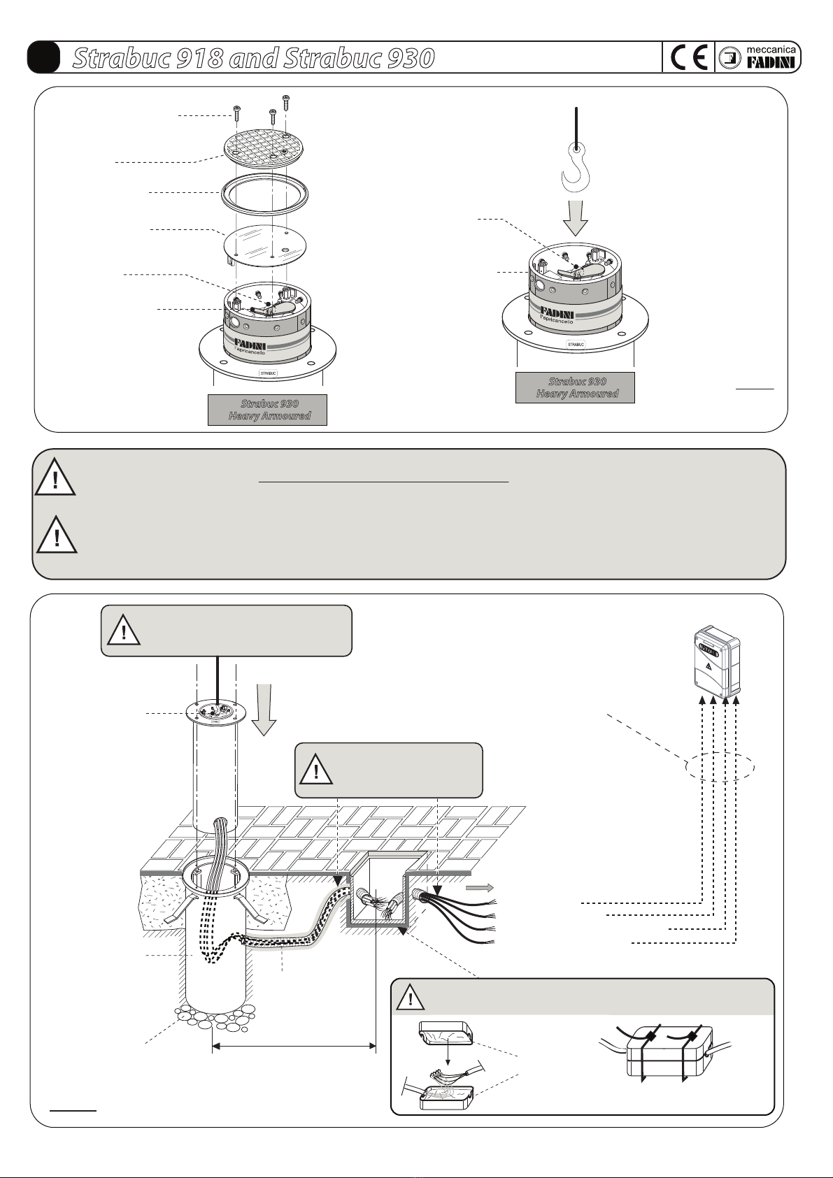
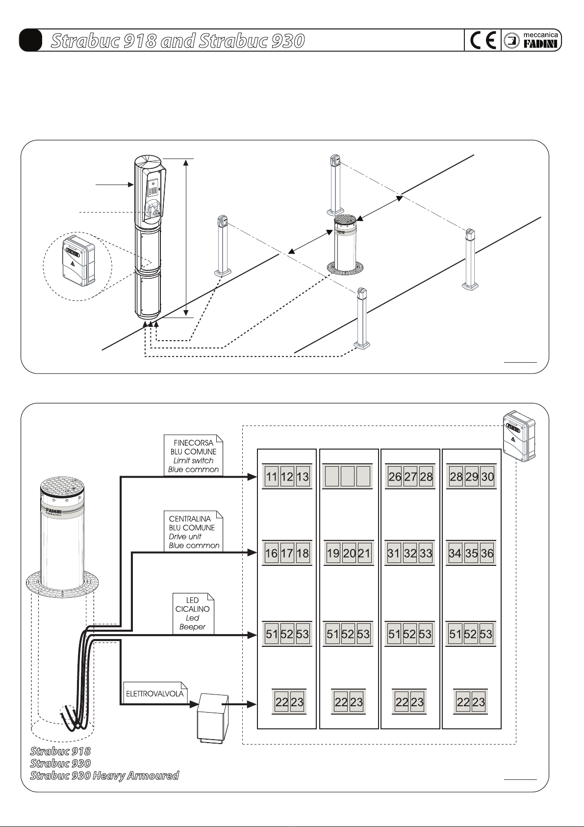
oil-hydraulic operator with a built-in hydraulic main unit. The Elpro S40 electronic programmer is installed externally, in a protected place. The trac control post comes
with a series of accessories that guarantee the necessary safety and the required operations, in order to make the operator suitable for installation in all public and
private settings.
STRABUC 918: bollard with retractable post of steel, 4 mm thickness. Stainless steel option available. For both versions an optional electro/solenoid-valve is possible for
automatic lowering in case of power failure.
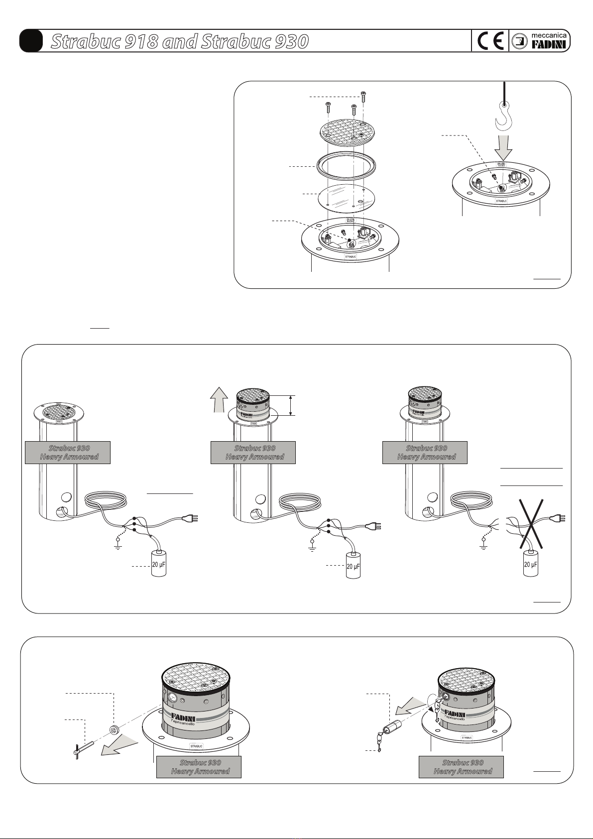
STRABUC 930 HEAVY ARMOURED: bollard with retractable post of steel, 12 mm thickness. On request the unit can be tted with an electro/solenoid-valve for automatic
lowering in case of power failure, and an armoured lock barrel, removable only by a custom-made key, to provide burglar-proof extra security to the post.
PRELIMINARY WARNINGS ON SAFETY AND GOOD OPERATION
Before commencing operator installation, it is essential to remember:
- That installation, checking, testing, risk analysis and subsequent maintenance work must be performed by authorised, qualied technicians.
- This operator has been designed for the use described in this manual only, and using at least the safety, control and indication accessoriesas here recommended.
- Any other application not explicitly indicated in this manual could cause malfunction, damage or personal injury.
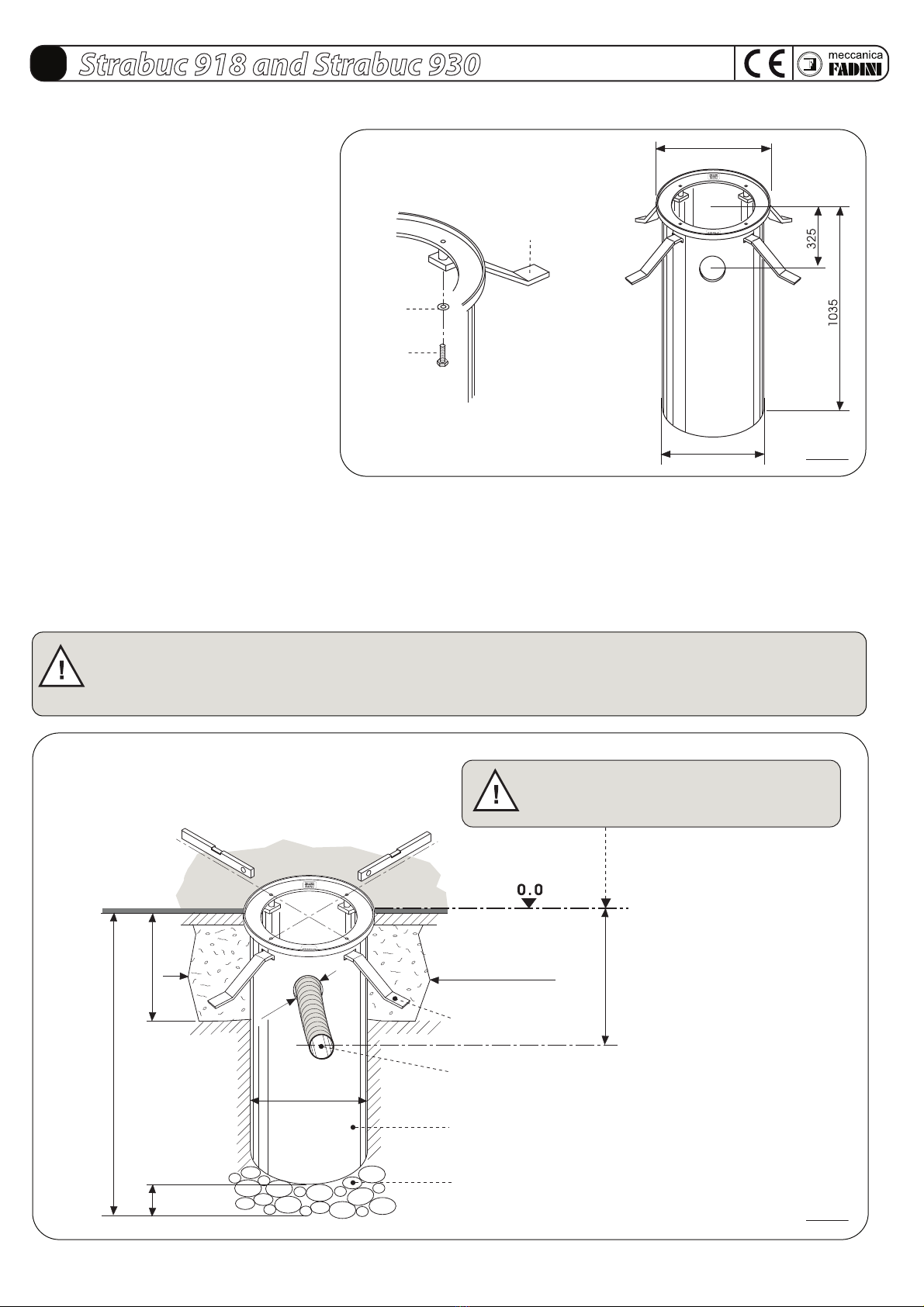
- To check that the ground is stable, to avoid subsequent settling or deformation in the trac control post installation area.
- To check that there are no nearby buried utility pipes.
- To check that there are no sources of electromagnetic disturbance in the immediate vicinity of and below the installation accessories such as to conceal or inuence
the magnetic/electromagnetic detection of the metal detectors and/or other electronic system control and management appliances.
- To check that the mains supply and voltage to the electric motor is 230 V at 50 Hz.
- The power supply to the operators are built-in motor must be made using electricity cables with a 1,5 mm² section for a maximum distance of 50 metres.
For distances of over 50 metres, use electric cables with sections suited to the installation.
- Always use the original components indicated by the manufacturer to replace elements or accessories.
- Meccanica Fadini declines all responsibility for improper use not specically indicated in this manual and any malfunction deriving from the use of materials or
accessories other than those indicated by the manufacturer.
- The manufacturer reserves the right to make changes to this manual without giving notice.
GB Strabuc 918 and Strabuc 930
The manufacturer, Meccanica Fadini, is not responsible for non-observance of good
installation practice and applications not indicated in this manual.
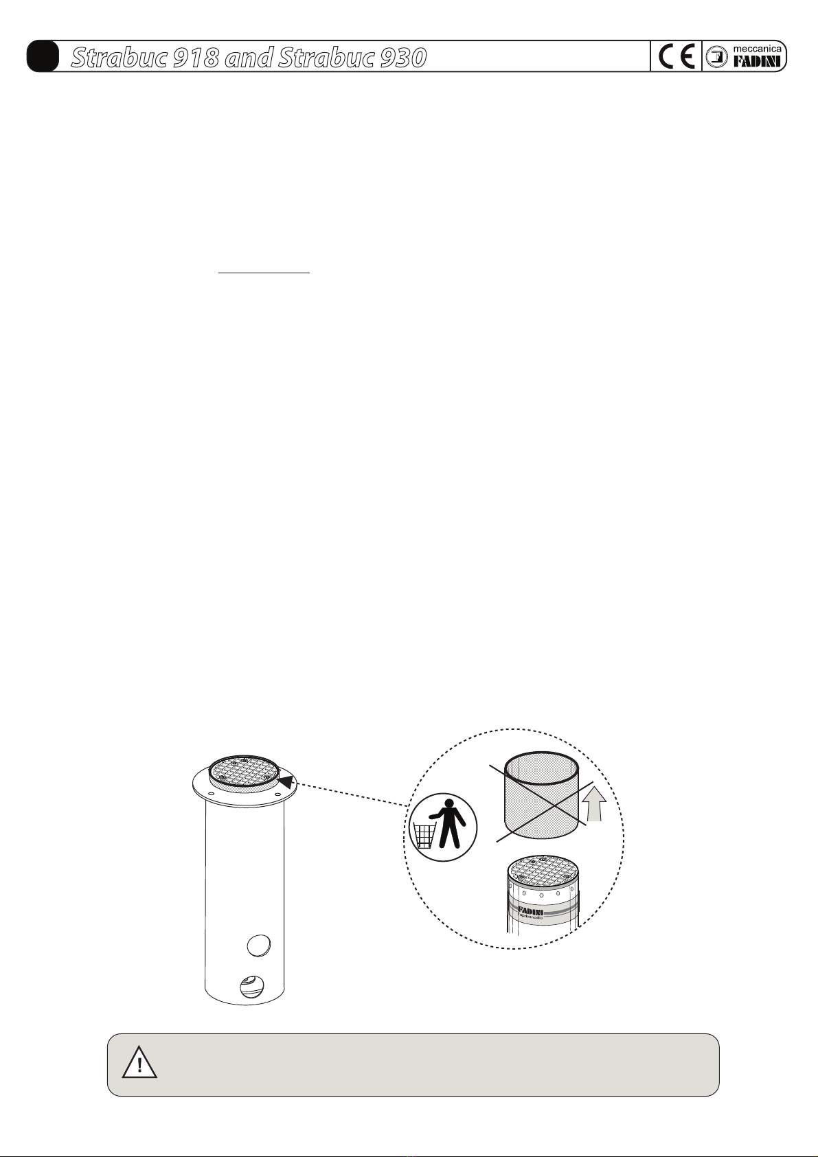
When the post is rst made to rise,
remove the rubber protection band
that is tted for
transport reasons.

- 19 -
GB Strabuc 918 and Strabuc 930
Universal triangular-recessed
release key
Manual release protection cap
M10x50 stainless steel
hexagonal socket head
clamping screws
Cover ange
Post cap with rubber edge
9x indicator LEDs Amber colour
Manual release protection cap
(Strabuc 930 heavy armoured)
Cap fastening ring nut
(Strabuc 930
heavy armoured)
M10x30 stainless steel
hexagonal socket head
cover-fastening screws
Rubber edge
Manual release
3x Guide rods
Piston rod
Limit switches
Hydraulic
main unit
Oil-hydraulic
piston
Manual
release tap
Security lock barrel Release lock cover
security ap
Led
Release lock cover cap
Release key
M10x50 stainless steel
hexagonal socket
head clamping screws
Customised keys for
security lock barrel
1- Limit switch
2- 230 V main unit power supply
3- 230 V voltage to LEDs
and buzzer (Optional on request)
4- 230 V solenoid valve (Optional on request)
Release solenoid valve
(Optional on request):
the column lowers completely
in blackout conditions
M8x20 TSEI inox screw
(Strabuc 930 heavy armoured)
Plastic plug to cover the hole
(Strabuc 930 heavy armoured)
Eyebolt for hitching
and hoisting
Type approved
retro-reecting adhesive
Flanged cylindrical
container
Electrical wires
STRABUC 930
Version of the Strabuc heavy bollard, 12 mm thickness, without
security armoured lock barrel.
STRABUC 930 HEAVY ARMOURED
Version with armoured lock barrel (optional) that can only be
removed using the personalised key, which lends the trac
post greater protection against forced entry (Pic. 2).
10 metres
20 μF capacitor
to be always tted
to each bollard
12,5 μF capacitor:
to be parallel tted
to the 20 μF capacitor
in case of failure/shortage
of power at starting
Fully retractable Fe 360 steel post.
Thickness of 4 mm (Strabuc 918).
Thickness of 12 mm (Strabuc 930 and
Strabuc 930 heavy armoured).
STAINLESS STEEL "INOX" option
only for Strabuc 918
PIC. 1
PIC. 2
STRABUC 930 HEAVY ARMOURED

- 20 -
GB Strabuc 918 and Strabuc 930
PIC. 3
OPTIONAL ACCESSORIES FOR COMPLETE INSTALLATION
230 V - 50 Hz
List of all operative accessories available:
1 - Miri 4 Led ashing light
2 - Elpro S40 electronic programmer with Siti 63 radio receiver
3 - Thermomagnet dierential switch with sensitivity 0,03 A (not provided)
4 - Two-channel metal mass detector
5 - Voltage stabilizer for each single solenoid/electro-valve coil
6 - Anti-intrusion cabinet
7 - Fit 55 recess-mounted photoelectric cell receiver
8 - Pre-assembled magnetic loop with power supply cable
9 - Post for Fit 55 photoelectric cell projector
10 - Strabuc 918 or Strabuc 930 oil-hydraulic trac control post
11 - Siti 63 Transmitter
12 - Post for Fit 55 photoelectric cell receiver
13 - Visual 344 control accessory housing post
14 - Chis 37 key switch
15 - Post moving hazard-warning indicator
16 - Recess-mounted Fit 55 photoelectric cell projector
17 - Two-light trac lights
18 - Birio A8 wall-mounted aerial
19 - Strabuc housing to be cemented into the ground (standard issue)

- 21 -
GB Strabuc 918 and Strabuc 930
- Assemble the support plates to be cemented into the
ground by tting them inside the slots in the cylindrical
container and fasten them by the provided screws
(Pic. 4).
- Dig a hole measuring 80x80 cm and approximately 1,20 m deep, where the Strabuc 918 or Strabuc 930 are to be installed: these measurements are adequate
for inserting and cementing the cylindrical container at ground level (Pic.5). Simultaneously, it is important to dig a hole in the ground to take a corrugated
exible pipe (max ø 50 mm) to the cylindrical container, passing through the hole as provided in the container, in order to house the electric wires to be
connected to the Elpro S40 electronic programmer (to be installed in a protected place).
- Before positioning the cylindrical container, arrange a 20 cm-deep layer of pebbles for rainwater drainage.
It is important that once the cylindrical container has been placed on the pebbles, the upper portion is ush with the ground level.
INSTALLATION OF THE CYLINDRICAL HOUSING TO BE CEMENTED INTO THE GROUND
PIC. 4
PIC. 5
Washer
Support plate
to be cemented
underground
M10x30
screws
Spirit level
Hole depth approximately 120-125 cm
30 cm
32 cm
ø 8 cm
15-20 cm
ø 40,5 cm
Concrete cast
80 x 80 cm
Support plates
to be cemented
Pipe, minimum ø 50, for housing electric wires
connected to the electric programmer
Strabuc housing
Loose pebble drainage layer
ø 405
ø 462
Spirit level
IMPORTANT: take care to avoid power or water pipes when digging. Arrange a water drainage layer beneath the dig.
IMPORTANT: once the housing has been positioned, before cementing, use a spirit level to ensure that it is absolutely level, to allow perfect
vertical movement of the trac control post.
IMPORTANT: the ooring or tarmac must be level
with the container upper edge.

- 22 -
GB Strabuc 918 and Strabuc 930
PIC. 6
PIC. 7
PIC. 8
INSTALLATION OF THE STRABUC 918 OR STRABUC 930 TRAFFIC CONTROL POST
INSTALLATION OF THE STRABUC 930 HEAVY ARMOURED (WITH ARMOURED LOCK BARREL)
Once the cement has set, proceed with installation of the
trac control post inside the cylindrical container.
For this operation, it is necessary to use equipment suitable
for hoisting and then placing it in the post seat, by hitching
to the eyebolt on the top of the retracting post cover,
having unscrewed and removed the three screws and the
cover. Before placing the Strabuc 930 inside the cylindrical
container, pass all the electric wires through the corrugated
tube connected to the Elpro S40 programmer: for this initial
phase, use a pull-out to be passed through the pipe rst
(Pic. 6 and Pic.10).
Before installing the Strabuc 930 Heavy Armoured version (with Armoured Lock Barrel) the trac post must be connected to the 230 Volt power supply (1).
Raise the post about 20 cm (2) and switch o the power supply (3) (Pic.7).
N.B. We recommend to t a 20 μF capacitor in parallel to the two phase/live wires to give the trac control post more power on starting.
M10x30 hexagonal
socket head post
cover fastening
screws
Rubber edge
Drilled ange for
edge tightening
Eyebolt
Protection
cap Armoured
lock barrel
Personalised
key
Triangular
prole key
about
20 cm
Connect the trac control post
to the 230 Volt power supply
20 μF
capacitor
CONNECT
the 230 V
power supply
DISCONNECT
the 230 V power supply
and drain the capacitor
20 μF
capacitor
Eyebolt
Under the retractable post cover,
there is an eyebolt for easy hoisting
1)
4) 5)
Raise the post about 20 cm, to allow
the subsequent extraction of the
reinforced lock barrel
N.B. If the post lowers instead of rising, switch over
the electric wires of the two“phases”, leaving the
“common”in place.
2) Once the post has been raised,
switch o the power supply
3)
Strabuc 930
Heavy Armoured
Strabuc 930
Heavy Armoured
Strabuc 930
Heavy Armoured
Strabuc 930
Heavy Armoured
Strabuc 930
Heavy Armoured

- 23 -
GB Strabuc 918 and Strabuc 930
6) 7)
Strabuc 930
Heavy Armoured
Strabuc 930
Heavy Armoured
M10x30 hexagonal
head screws
Cover
Rubber edge
Drilled ange
for edge tightening
Eyebolt
Eyebolt
Corrugated
exible tube
about 6 - 8 metres
Pebble drainage layer
Cylindrical
container
to becemented
into the ground
Eyebolt
Retractable
post
Manual release
cover security ap
PIC. 9
PIC. 10
ATTENTION: as Strabuc 918 or Strabuc 930 come complete with a series of electric cables, each one 10 metres long, during all these
trac post installation operations, never tug at or charge electric wires for any reason. During Strabuc 918 or Strabuc 930 maintenance
or removal operations DO NOT CUT THE ELECTRIC WIRES, remove them from the pipes.
Align the trac post cylinder holes
with those in the cylindrical container
cemented into the ground.
Pull the electric cables to
the Elpro S40 programmer
without tugging
For distances greater than 10 metres, make extensions using seale
djunction boxes inside an accessible dividing box.
Below ground wiring housed inside
a corrugated pipe
Elpro S40
1 - Limit switches
Junction
boxes
Seal the junction boxes
using bands
2 - Power supply 230 V
3 - LED and buzzer power (optional)
4 - Solenoid valve (optional)
ATTENTION: measure the distance between the trac post installed and the Elpro S40 programmer: once the Strabuc has been
positioned and fastened, all the electric cables must rest freely on the bottom of the cylindrical housing. If the distance is greater, the
wires should be extended using sealed joints (junction boxes) inside an accessible dividing box, according to good installation practice:
this will prevent malfunctions and will guarantee ecient operation over time.

- 24 -
GB Strabuc 918 and Strabuc 930
PIC. 11
PIC. 12
PIC. 13
Once all the electric wires have been put in place, terminate by fastening the Aluminium collar and the Cover: lubricate the xing screws of the collar and retractable
post cover using grease (Pic. 11).
ARRANGING THE MAGNETIC COILS
IMPORTANT: check that there are no sources of disturbance such as to conceal or inuence the magnetic/electromagnetic detections of any metal detector
coils in the immediate vicinity of the installation accessories.
The magnetic coil safety accessory is always activated to detect transiting road vehicles. It prevents the trac post from rising when vehicles pass over the coils.
A hole must be prepared (see relative instruction sheet).
Specications should always be observed for correct magnetic coil operation.
Collar fastening screws
Collar
Screws for fastening cover
Cover
Rubber edge
Drilled ange
for rubber edge tightening
Entry coil Entry coil
Exit coil
Exit coil
GREASE
IMPORTANT: LUBRICATE THE FOUR
CLAMPING SCREWS IN THE COLLAR
AND THE THREE COVER SCREWS WITH
GREASE.
- Pre-assembled loop 6 meters across
(optional in the catalogue).
- Pre-assembled loop 12 meters across
(optional in the catalogue).
Power supply cable
10 meters max.,
pre-tted to the loops
Strabuc 918
Strabuc 930
min 80 cm
Metal detector. See instructions
included with the equipment
(optional in the catalogue).

- 25 -
GB Strabuc 918 and Strabuc 930
PIC. 14
PIC. 15
The photoelectric cells must be installed at a minimum working distance as indicated in Pic. 14.
ARRANGEMENT OF THE PHOTOELECTRIC CELLS
DIAGRAM OF THE ELECTRICAL CABLES OF THE BOLLARD
The 2 or 3-module Visual 344 is a metal accessory used to house the Elpro S40 in exposed positions, in those installation situations in which the programmer cannot
be wall- or recess-mounted. It has also been designed for the installation of possible control accessories such as intercom systems or key switches, in the immediate
vicinity of the trac post (pic. 12).
ARRANGEMENT OF VISUAL 344
Visual 344
ø 275
CHIS 37
Elpro S40
Elpro S40
Strabuc n°1
common
common
common
common
common
common
common
common
Strabuc n°2 Strabuc n°3 Strabuc n°4
Below ground wiring housed inside a corrugated sheath
10 m
10 m
Stabilizer
10 m
10 m
min. 1,0 m min. 1,0 m
Photoelectric cells
FIT 55
Photoelectric cells
FIT 55
Photoelectric cells
FIT 55
Photoelectric cells
FIT 55
1.890
common
common
common
common
beeper
beeper
beeper
beeper
led
led
led
led
13 14 15

- 26 -
GB Strabuc 918 and Strabuc 930
General description: the electronic panel Elpro S40 is tted with a microprocessor to manage up to four retractable trac controlposts in the Strabuc series. With its
single-phase 230 V power supply, it satises the Low Voltage 2006/95 CE and Electromagnetic Compatibility 2004/108/CE safety standards and should therefore be
installed by a qualied technician in compliance with applicable regulations.
Elpro S40 stands out for its ability to monitor system faults and malfunctions (ISC).
ISC = Integrated Supervision Circuit is a special Elpro S40 feature that monitors the whole electronic board aimed at detecting any component faults, or system
accessory malfunction, if the operator is tted with a release solenoid valve this allows the retractable post to lower.
The Elpro S40 programmer should be installed in a dry, protected place, inside its own container or, in the case of additional components for operating the control
and safety accessories, it should be housed inside a Visual 344 or a cabinet certied for external use.
- The Elpro S40 programmer is powered using electric wires with a 1,5 mm² section, with a cut-o dierential switch over a maximum distance of 50 metres.
For distances of over 50 metres we recommend using electric cables with appropriate sections according to good installation practice. For all accessories external to
the electric panel, electric cables with 1 mm² wires may be used.
- The three-light trac lights must be connected by a 4 x 1,5 mm² wire electric cable and the card powered 230 V to terminals 60-61 on the plug-in card.
ELECTRICAL CONNECTIONS TO THE ELPRO S40 CONTROL BOARD
Red
Yellow
Green
Common
Power supply
230 V 50 Hz
1 A fuse
CONNECTOR FOR 3 LIGHT
TRAFFIC LIGHTS,
MAX100 W PER BULB
24 V DC OUTPUT
SUPPORT FOR
PLUG-IN
RADIO CARD
DIP-SWITCH
Elpro S40
Input P
Stabilizer: for Strabuc version
with electro/solenoid-valve
Drwg. No. 4555
ELPRO S40
ON
OFF
20 VA 50/60 Hz
Brown
BrownBlack
Black
Common Blue
T1
Operating Time
1 s - 22 s
T2
Pause Time
1 s - 180 s
Common Blue
12 Vdc
12 Vdc
230 V
100 W MAX
INDICATOR
LEDs
FLASHING LIGHT
230 V 100 W max
BEEPER
(optional)
230 V
100 W MAX
TRANSFORMER
COMMON
M4 CLOSING LIMIT SWITCH
(Post raised)
M4 MOTOR
4th trac control post
M2 MOTOR
2nd trac control post
M1 MOTOR
1st trac control post
M3 MOTOR
3rd trac control post
M4 OPENING LIMIT SWITCH
(Post lowered)
M3 CLOSING LIMIT SWITCH
(Post raised)
M3 OPENING LIMIT SWITCH
(Post lowered)
M2 CLOSING LIMIT SWITCH
(Post raised)
M2 OPENING LIMIT SWITCH
(Post lowered)
M1 CLOSING LIMIT SWITCH
(Post raised)
M1 OPENING LIMIT SWITCH
(Post lowered)
OUTPUT 24 V - 250 mA for max. load:
- 2 pairs of photoelectric cells
- 1 Radio Receiver
RADIO
PHOTOELECTRIC CELL
OR MAGNETIC COIL
Contact terminal
Pedestrian passage
Trac control post M1 MOTOR
STOP
CLOSE
OPEN
COMMON
Indicator light 24 V - 3 W max
COMMON
COMMON
COMMON
COMMON
COMMON
COMMON
NEUTRAL
PANEL POWER SUPPLY
230 V ± 10% 50 Hz
SINGLE PHASE
PHASE
Secondary Fuse
Transformer
F4 = 2 A
Fuse
M4 Motor
F6 = 5 A
Cond. 20 μF
M3
Cond. 20 μF
M4
Cond. 20 μF M2
FN
Anti-disturbance lter
Cond. 20 μF M1
Fuse
M3 Motor
F7 = 5 A
Primary Fuse
Transformer
F3 = 630 mA
SOLENOID-VALVE
POWER SUPPLY
Fuse for Solenoid Valve,
Beeper, Flashing Light
and LED F5 = 2 A
Fuse Motor M2
F2 = 5 A
Fuse Motor M1
F1 = 5 A
Red
Yellow
Green
PIC. 16

- 27 -
GB Strabuc 918 and Strabuc 930
FIRST OPERATION MANOEUVRES
ATTENTION: do not power the system until all the wiring needed for operation has been performed.
VERSION OF STRABUC 918 OR STRABUC 930 WITH SOLENOID VALVE
In the version with solenoid valve no manual overriding action is needed, and in case of power failure the post descends automatically ush with pavement level.
To enable the solenoid valve to operate properly, the electric wires labelled “ELECTROVALVE” from the post assembly are to be connected, through the voltage
stabilizer, to terminals 22 and 23 in the Elpro S40 control box (pic. 20).
Having terminated installation of the trac control post and all the safety and control accessories
(all of the NC contacts on the Elpro S40 board are to be bridged - pic.18), and the respective connections
with the Elpro S40 programmer, and having completed thorough risk analysis, the rst operation
manoeuvres can be performed.
If you have a radio transmitter, encode the radio receiver according to the relative instructions before
giving the command to raise the retractable post, or give the manoeuvre command using a key switch.
Once power is supplied, connect the motor/pump cable and, satised that the limit switch LEDs are
properly alight, the post should move up on the rst commanding pulse; should it fail, disconnect power
supply and swap the connections to the live terminals.
Strabuc n°1
common
Strabuc n°1 Strabuc 918 or Strabuc 930
with solenoid valve
L8 = Limit switch open M1, normally ON,
it goes o when the post is in down position
L9 = Limit switch close M1, normally ON,
it goes o when the post is in up position
Stabilizer
20 μF
NC
All NC contacts
are to be closed
230 V
common
PIC. 17
PIC. 18
PIC. 19
PIC. 20
Strabuc n°1
common
Strabuc n°1
common
Should the motor fail
to drive the post up by
rst pulsing, swap the
connections to the electric
motor live terminals only
1st pulse
In case of multiple installations go
through the same procedure with each post
In case of multiple installations go through the same procedure with each post
Strabuc 918 or Strabuc 930
in raised position:
Access Closed
Strabuc 918 or Strabuc 930
with solenoid valve
Strabuc 918 or Strabuc 930
with solenoid valve Strabuc 918 or Strabuc 930
with solenoid valve
Stabilizer
230 V
230 V
NO
Make the electrical connections to the limit switches, then supply with electric power and check the LED status rst of all: with the post in down position
LED No. L8 must be OFF and LED No. L9 ON, otherwise swap the connections to terminals 11 and 12.
ATTENTION: it is required that the post stay
completely lowered: should the post rise during
installation, override by the release key and
lower the post manually, then tighten again.

- 28 -
GB Strabuc 918 and Strabuc 930
PIC. 21
PIC. 22
RELEASE OPERATIONS FOR MANUAL LOWERING OF STRABUC 918 OR STRABUC 930
The trac control post is tted with a system for manual post lowering. The universal triangular-recess key provided removes the protection plug and subsequently
releases the retracting trac control post, which lowers to pavement level with simple manualpressure (pic. 21).
Once the post has been lowered manually, it only rises again following an electrical command impulse.
RELEASE OPERATIONS FOR MANUAL LOWERING OF THE STRABUC 930 HEAVY ARMOURED
Strabuc 930 Heavy Armoured posts can be lowered manually by following the operations shown in picture 22.
Insert and turn the
release key
Manual lowering of the post Tighten
Tighten
1)
1)
3) 4) 5) 6)
2)
2) 3) 4)
Strabuc 930
Heavy Armoured
Strabuc 930
Heavy Armoured
Strabuc 930
Heavy Armoured
Strabuc 930
Heavy Armoured
Strabuc 930
Heavy Armoured
Triangular
prole key
Triangular
prole key
Armoured lock
barrel protection cap
Release
protection cap
Armoured
lock barrel
Personalised key
for armoured
lock barrel
Insert and turn the
release key
Manual lowering
of the Strabuc 930
Heavy Armoured version

- 29 -
GB Strabuc 918 and Strabuc 930
REMOVING ONLY THE POST OF STRABUC 930 HEAVY ARMOURED
It is possible to remove Strabuc 930 Heavy Armoured from its seat by following steps 1) and 2) as described in pic. 23.
But in order to remove only the retractable post, carry on with the steps as subsequently described in pic. 23.
1) 2) 3)
Strabuc 930
Heavy Armoured
Strabuc 930
Heavy Armoured
Strabuc 930
Heavy Armoured
Strabuc 930
Heavy Armoured
Strabuc 930
Heavy Armoured
PIC. 23
4) 5)
6) 7)
M10
M10
To remove only the retractable post: with the Strabuc 930 Heavy Armoured version
raised using the winch, unscrew the three clamping nuts and respective washers,
positioned below the Cylindrical container.
ATTENTION: during this operation the cylindrical housing will drop: it is
therefore recommended to support it.
Unscrew the Cap protecting the Armoured lock barrel using the
triangular prole key
Remove the three Eyebolts, the post Cover, the Rubber edge
and the Drilled ange
Unscrew the three long hexagonal nuts
with their respective Clamping screws and
remove the Retractable post to leave the
Piston - hydraulic main unit set exposed
Remove the whole Reinforced Lock Barrel by inserting the
personalised key and turn anticlockwise
Clamping nuts
and washers
IMPORTANT: do NOT loosen or tighten the three
axial alignment dowels of the internal group.
- VIEW FROM BELOW -
CYLINDRICAL HOUSING
Protection cap
Eyebolts
Post cover
Rubber edge
Drilled ange for
edge tightening
Manual release
cover security
ap
Armoured lock barrel
Personalised key for
armoured lock barrel
Triangular
prole key
ATTENTION: during the assembly phase it is important to
reposition the internal unit in exactly the same position as
before without screwing or loosening the three axial
alignment dowels.

- 30 -
GB Strabuc 918 and Strabuc 930
32
85
100
58
73
27
22
1.000
Vehicle SPEED (km/h)
Vehicle MASS
(kg)
Various factors, such as the compaction index, soil permeability
coecient and kind of concrete may reduce the values
indicated in the diagram even signicantly.
Various factors, such as the compaction index, soil permeability
coecient and kind of concrete may reduce the values
indicated in the diagram even signicantly.
Vehicle MASS
(kg)
Vehicle SPEED (km/h)
1.400
2.100
3.000
1.000
1.400
2.100
3.000
34
24
87
120
71
29
103
40.000 JImpact resistance
Crash resistance
Impact resistance
Crash resistance
280.000 J
45.000 J
410.000 J
Strabuc 918
Static load resistance:
The static load acting on the Strabuc 918 when completely lowered is
considered as the weight a 20.000 kg lorry exerts when parked on or
passing over the trac control post.
Practical tests with fully laden lorries have conrmed this result.
Maximum static load 20.000 kg
Strabuc 918 Strabuc 930
RESISTANCE DATA
VIOLENT COLLISION RESISTANCE
stroke 700 mm
b (mm)
v (km/h)
M (kg)
20.000 kg
Strabuc 930
Static load resistance:
The static load acting on the Strabuc 930 when completely lowered is
considered as the weight a 20.000 kg lorry exerts when parked on or
passing over the trac control post.
Practical tests with fully laden lorries have conrmed this result.
Maximum static load 20.000 kg
PIC. 24
PIC. 25

- 31 -
GB Strabuc 918 and Strabuc 930
DECLARATION OF CONFORMITY
of the Manufacturer
Manufacturing
company:
Model:
Strabuc 918 is to be sold and installed as a comprehensive "Automatic System", including the accessories and components
as recommended by the Manufacturing Company. In observance of the current directives, any automation is to be regarded
as a "machine". Therefore it is required that all the applicable safety norms are strictly complied with by installation agents,
who are also required to issue a Declaration of Conformity.
The manufacturing company is not liable for incorrect applications or misuse of its products that are declared to be produced
in compliance with the following norms:
- Analysis of the risk and actions to cure them: EN 12445 & EN 12453
- Low Voltage Directive: 2006/95 CE
- Electro-magnetic Compatibility Directive: 2004/108/CE
In order to certify the product the Manufacturer declares under his own responsability
the compliance with the PRODUCT regulations under the NORMS EN 13241-1
Oil-hydraulic bollard, fully retractable into the ground,
for trac control in public areas
hereby declares under its own responsibility that:
IS IN COMPLIANCE WITH THE NORMS ......... 2006/42/CE
and that:
STRABUC 918
GB Date: 10-01-14
The Responsible Manager
Responsible Manager
made in Italy
the gate opener
DECLARATION OF CONFORMITY
of the Manufacturer
Manufacturing
company:
Model:
Strabuc 930 and Strabuc 930 Heavy Armoured are to be sold and installed as a comprehensive "Automatic Systems", including
the accessories and components as recommended by the Manufacturing Company. In observance of the current directives,
any automation is to be regarded as a "machine". Therefore it is required that all the applicable safety norms are strictly
complied with by installation agents, who are also required to issue a Declaration of Conformity.
The manufacturing company is not liable for incorrect applications or misuse of its products that are declared to be produced
in compliance with the following norms:
- Analysis of the risk and actions to cure them: EN 12445 & EN 12453
- Low Voltage Directive: 2006/95 CE
- Electro-magnetic Compatibility Directive: 2004/108/CE
In order to certify the product the Manufacturer declares under his own responsability
the compliance with the PRODUCT regulations under the NORMS EN 13241-1
Oil-hydraulic bollard, fully retractable into the ground,
for trac control in public areas
hereby declares under its own responsibility that:
IS IN COMPLIANCE WITH THE NORMS ......... 2006/42/CE
and that:
STRABUC 930
GB Date: 10-01-14
The Responsible Manager
Responsible Manager
made in Italy
the gate opener

- 32 -
GB Strabuc 918 and Strabuc 930
Strabuc 918 and Strabuc 930
Strabuc 918
Strabuc 918
Strabuc 930
Strabuc 930
Strabuc 930 Heavy Armoured
700920
ø 100
1.620
10
700
700
10
920
1.620
1.035
325
1.010 25
10
ø 275
thickness 4 mm
ø 325
thickness 6 mm
ø 450 ø 450
ø 462
ø 405
≠ 40x10
ø 80
ø 345
ø 425
ø 100
ø 275
thickness 12 mm
ø 275
ø 325
thickness 6 mm
ø 425
10 metres long each 10 metres long each
ORDINARY MAINTENANCE AND WASTE DISPOSAL
For optimal performance of the system over time and operation in compliance with safety regulations, correct maintenance and checks must be
performed on the operator, the electronic equipment constituting the installation and on wiring performed.
The entire installation should be carried out by authorized technicians, who are also to ll in the Maintenance Form as indicated in the Norms Book
(available on request):
1° - Oil-hydraulic operator: maintenance check every 6 months.
2° - Electronic equipment and safety systems: a monthly maintenance check.
3° - Ordinary and extraordinary maintenance to be agreed upon between end user/contractor and installation agent.
4° - Packaging materials such as cardboard, nylon, polystyrene, etc. should be disposed of using specialised waste collection rms.
IF THE OPERATOR IS REMOVED
1° - Disconnect the main switch before opening the lid of the electric cable junction box.
2° - Do not cut the electric wires, rather remove them from the terminal board loosening the clamping screws inside the dividing box.
Via Mantova, 177/A - 37053 Cerea (VR) Italy
Tel.+39 0442 330422 - Fax +39 0442 331054
The manufacturer reserves the right to make amendments to this manual without priornotice and declines all responsibility for any errors, personal injury or damage to property.
ELECTRIC MOTOR
Power output 0,25 kW (0,33 HP)
Power consumption 330 W
Power supply voltage 230 V
Frequency 50 Hz
Absorbed current 1,8 ÷ 3,5 A (6 A max)
Motor rotation speed 2.800 rpm
Intermittent service S3
CYLINDRICAL CONTAINER - to be cemented
Material "FE" sheet steel
Treatment Hot dip galvanization
Calandered sheet metal thickness 1,5 mm
Fixing ange thickness 10 mm
4x support plates at 40x10
Total weight 30 kg
Strabuc 918
Strabuc 918
Post diameter Ø 275 mm
Post thickness 4 mm
Post height 700 mm
Plunger diameter 30 mm
Rod diameter 16 mm
Net rod travel 740 mm
Calibrated thrust 18 daN
Frequency of use very intensive
Rising time ~ 6,1 s
Lowering time ~ 5,7 s
Protection class - Strabuc 918 IP 67
LED power supply 230 V - 50 Hz
LED lights 24 V
Post nishing Powder coating polyester
RAL 1028 - Melon yellow
Post material “FE 360”steel
Stainless Steel/Inox version “AISI 304”
Impact resistance 40.000 J
Crash resistance 280.000 J
Maximum static load 20.000 kg
Complete weight of Strabuc 918 140 kg
OIL-HYDRAULIC MAIN UNIT
Hydraulic pump P10
Pump ow rate 4,45 litres/1’
Operating pressure 2 MPa (20 bar)
Max pressure 3 MPa (30 bar)
Operating temperature - 20 °C + 80 °C
Oil container capacity 1,5 litres
Oil type Oil Fadini - code 708L
Protection class IP 67 (IP 65 with electrovalve)
Strabuc 930 - Strabuc 930
Heavy Armoured
Heavy Armoured
Post diameter Ø 275 mm
Post thickness 12 mm
Post height 700 mm
Plunger diameter 30 mm
Rod diameter 16 mm
Net rod travel 740 mm
Calibrated thrust 18 daN
Frequency of use very intensive
Rising time ~ 11,6 s
Lowering time ~ 9,9 s
Protection class - Strabuc 930 IP 67
LED power supply 230 V - 50 Hz
LED lights 24 V
Post nishing Powder coating polyester
RAL 7016 - Anthracite gray
Post material “FE 360”steel
Impact resistance 45.000 J
Impact resistance 410.000 J
Maximum static load 20.000 kg
Complete weight of Strabuc 930 180 kg
2019/04
GB 2012/19/UE Directive
Re. disposal of electric
and electronic waste
DISPOSE PROPERLY OF MATERIALS
ARMFUL TO THE ENVIRONMENT
This manual suits for next models
1
Table of contents
Other fadini Safety Equipment manuals