RoadHog RH3075 User manual

MANUAL
Operation
Maintenance
Service
Parts
Warranty
RH3075
RH4075
Road Hog
Cold Planer
For units built prior to 5/10
Serial number ___________________________
Date released for shipment _________________
2
INTRODUCTION
Thank you for your investment in Roadhog Inc. We are confident that you will find that
your Roadhog Inc attachment is the easiest to operate, safest, most durable, and most
efficient attachment on the market.
Your Roadhog Inc is equipped with high performance, heavy duty components. To en-
sure that these components operate properly and effectively, this manual must be fol-
lowed. If any question regarding the operation or performance of this attachment ex-
ists, contact your Roadhog Inc dealer at once.
This manual contains safety instructions, guidelines for efficient operation, trouble-
shooting tips, and service maintenance procedures. When applicable, the terms “right”
and “left” are referenced from a sitting position and facing forward in the loader.
Throughout this manual, information is provided in boxes and highlighted by the word
IMPORTANT. This information should be read carefully. If complied with, it will improve
the operating efficiency of the unit and provide directives that will minimize costly
breakdowns and extend the life of the machine.
This warning symbol appears throughout this manual and
indicates that a safety hazard may exist if the information
given is not properly followed. When the warning signal is
encountered in the manual or on the unit, Be Alert! Your
personal safety is involved!
For more copies of this manual or the necessary safety decals, contact your Roadhog
Inc dealer.

3
TABLE OF CONTENTS
Page
SAFETY DECALS …………………………………………………………………………….4
SAFETY PRECATUTIONS …………………………………………………………………..5
MANDATORY SAFETY SHUTDOWN PROCEUDRE ……………………………………5
SAFETY ………………………………………………………………………………………..6
SETUP ………………………………………………………………………………………….7
OPERATION …………………………………………………………………………..…..8-13
MAINTENANCE......…... ………………………………………………...…………...…14-15
SERVICE..…………………………………………………………………………………16-17
CHASSIS GROUP PARTS DRAWING……….………………………...……………..18-21
ATTACH GROUP PARTS DRAWING……….………………………...….…….….....22-27
DRIVETRAIN AND DRUM GROUP PARTS DRAWING…...………...……….….....28-29
ENGINE GROUP ……………………..……….……………………………....………...30-31
CLUTCH GROUP………………………………………………………………………...32-33
HYDRAULIC GROUP PARTS DRAWING……………………………………….…...34-35
HYDRAULIC VALVE ( TILT, DEPTH AND SIDESHIFT ) PARTS DRAWING...…36-37
HYDRAULIC VALVE ( CLUTCH ENGAGEMENT ) PARTS DRAWINGS…..……38-39
HYDRAULIC SCHEMATIC...……………………………...….…………………..…..…...40
ELECTRICAL DISCONNECT POINTS PRIOR TO WELDING…………….…………..41
ELECTRICAL GROUP ( MASTER PANEL)………………………………………….42-43
ELECTRICAL GROUP ( REMOTE TRANSMITTER )……………………...……….44-45
ELECTRICAL SCHEMATICS………….…………………...……………….…..……..46-47
DECAL GROUP PARTS LIST………...…….…………………………...…………..........48
SPECIFICATIONS ……………………………………………...….………………………..49
WARRANTY ………………………………………………………...……………………….50
WARRANTY CLAIM FORM………………………………………..……………………….51
NEW MACHINE DELIVERY REPORT…………………………………………………….52
OWNER INFORMATION CARD……………………………………………………………53
4
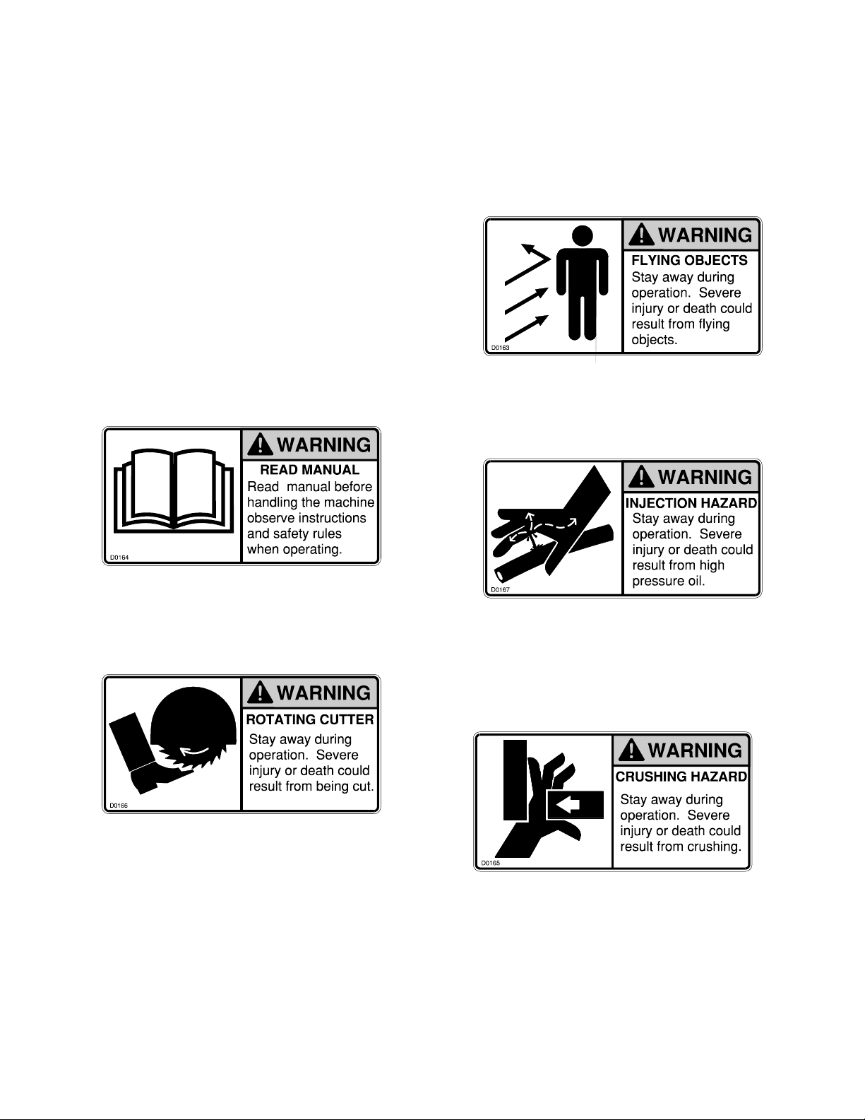
SAFETY DECALS
The safety decals existing on the
attachment should be clearly read-
able and always followed. The lo-
cation and description of the de-
cals is shown in the parts diagram.
The CRUSHING HAZARD decal
warns the operator and bystanders
to stay away during operation.
The ROTATING CUTTER decal
warns the operator and bystanders
to stay away during operation.
The READ MANUAL decal warns
the operator to read this manual
before operating the attachment. The INJECTION HAZARD decal
warns the operator and bystanders
to stay away during operation.
The FLYING OBJECTS decal
warns the operator the operator
and bystanders to stay away dur-
ing operation.
5
SAFETY
PRECAUTIONS
ACCIDENTS ARE
PREVENTABLE WITH YOUR HELP
Understand and comply with applicable
laws and regulations.
Call local utilities before you dig.
1-888-258-0808
Know the location of underground gas, water
and electrical lines.
Inspect area for holes, drop-offs, or unstable
ground.
Know the weight limitations of operating
surfaces and clearances.
Remember: Safe operation begins with the
operator.
BEFORE OPERATING THIS
EQUIPMENT, THE FOLLOWING
SAFETY INFORMATION SHOULD BE
READ AND UNDERSTOOD. IN
ADDITION, EACH INDIVIDUAL
WORKING WITH THE EQUIPMENT
SHOULD BE FAMILIAR WITH THE
SAFETY PRECAUTIONS
Exercise extreme caution when attaching and removing the attachment, operating with
other workers present, and servicing the unit.
Roadhog Inc makes operator safety a priority when designing machinery. Exposed
moving parts are guarded whenever possible for safety. However, not all moving parts
can be shielded in order to ensure proper operation. This operator’s manual and
safety decals on the machine provide important safety information when ob-
served closely If safety decals become difficult to read, replace them immediately. (see
“Safety Decals”).
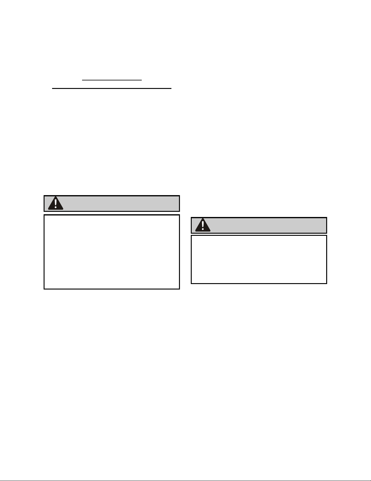
MANDATORY SAFETY
SHUTDOWN
PROCEDURE
BEFORE cleaning, adjusting, lubricating,
or servicing this unit, ALWAYS follow the
MANDATORY SAFETY SHUTDOWN
PROCEDURE:
1. Lower loader arms and roll attach-
ment forward until it is flat on the
ground.
2. Apply loader parking brake and stop
the loader engine.
3. Remove loader key and keep with
you while you are working on the at-
tachment.
4. Turn cold planer engine off and lock
control panel using the PIN security
feature.
FAILURE TO FOLLOW THE
PROCEDURES BEFORE CLEANING,
ADJUSTING, LUBRICATING, OR
SERVICING THIS UNIT COULD LEAD
TO SERIOUS INJURY OR DEATH.
WARNING
WARNING

6
SAFETY
A careful operator is the best protection
against accidents. Most accidents involv-
ing operators of industrial equipment are
caused by failure to observe basic safety
precautions. Know the equipment and
worksite before you operate. Familiarize
yourself with the safety precautions listed
below.
THE FOLLOWING PRECAUTIONS
MUST BE OBSERVED FOR THE
SAFETY OF THE OPERATOR
AND/OR SERVICE PERSONNEL.
1. Read and observe all safety informa-
tion and decals on the loader and at-
tachment BEFORE operating the
unit!
2. Refer to the SAFETY section of your
skid loaders operator’s manual and
observe all safety recommendations
set forth in the manual.
3. When loading, keep attachment as
low to ramps & trailer as possible.
4. Always lower the loader arms fully
before leaving the operator’s seat.
NEVER CRAWL UNDER RAISED
LOADER ARMS.
5. BE SURE to raise the attachment
totally off the ground BEFORE side-
shifting.
6. CAREFULLY inspect ALL hydraulic
hoses and connections on a routine
basis; Always use a piece of card-
board when searching for leaks.
7. BE SURE to exercise the above MAN-
DATORY SAFETY SHUTDOWN pro-
cedure, BEFORE proceeding with any
work on the attachment.
NEVER USE YOUR HANDS AS
ESCAPING FLUID UNDER PRESSURE
CAN PENETRATE THE SKIN CAUSING
SERIOUS INJURY. IF HYDRAULIC
FLUID DOES PENETRATE THE SKIN,
SEEKIMMEDIATE MEDICAL
ATTENTION BY A DOCTOR FAMILIAR
WITH THIS TYPE OF INJURY OR
GANGRENE MAY RESULT.
NEVER ALLOW HANDS OR FEET
NEAR ANY WORKING PART OF THE
ATTACHMENT UNLESS THE
MANDATORY SAFETY SHUTDOWN
PROCEDURE HAS BEEN
COMPLETED.
WARNING WARNING
WARNING
WARNING

7
READ THIS ENTIRE MANUAL AS
WELL AS THE DECALS ON THE
ATTACHMENT BEFORE ATTEMPT-
ING ANY MAINTENANCE, SERVICE
OR SETUP OF THE UNIT.
SETUP
Hoses / Fittings
Hydraulic fittings are used to connect
all hoses. All fittings should be tight
and free of hydraulic leaks. Hoses
must be free of crimps or cuts that
might result in leakage. Check your
attachment before operation to make
sure all hose routings are kink-free and
allow for maximum movement of all
depth and sideshift functions required
during normal operation.
Wire Harness
The wiring harnesses should be routed
to prevent catching or pinching when
sideshifting or lowering the drum fully
into the cut.
Drum Assembly
For proper operation, teeth must be
installed in every holder on the drum.
Welds on holder and blocks should
be inspected weekly for cracks. Any
cracks should be fixed as soon as pos-
sible. Teeth should be inspected daily
for wear. Tooth should be allowed to
freely rotate within their holders.
Holders should be inspected daily for
wear. Holder wear is not typically cov-
ered under warranty. Holders may be
hardfaced to replace worn holder ma-
terial.
WARNING
Although the Roadhog Inc is supplied
fully assembled, some simple checks
should be performed before operation
begins.
Safety Decals
The safety decals existing on the attach-
ment should be clearly readable and al-
ways followed. The location and descrip-
tion of the decals is shown in the ex-
ploded diagram. Copies of the decals are
shown in “Safety Decals” section.
Lubrication
The deadshaft bearing, supporting the
right hand side of the drum, should be
lubricated at least once a week. Daily
lubrication may be required during heavy
use or in extremely dusty conditions.
The planetary oil should be changed af-
ter the first 50 hours of operation, and
then once a year after that.

8
OPERATION
The cold planer is an engine powered attachment intended for cutting asphalt or con-
crete surfaces. The performance of the attachment can vary greatly depending upon
how it is used and operated. Therefore, the recommended operating procedures con-
tained within this manual should be followed at all times for maximum productivity.
Prior to operating the attachment, read this entire manual. Follow all safety guidelines
in this manual and safety decals on the unit. Make sure that all guards, shields, and
decals are in place and in good condition prior to operation.
Attaching to Loader
Pin on style mounting
To attach the unit to the loader, start the loader and rotate the coupler out. Move
the machine forward and align the male bosses on the male portion of the loader
attach with the female bosses on the Roadhog. Insert pins and secure pins to
bosses per the manufacturers recommended procedure.
Attaching to Loader
quick attach style mounting
To attach the unit to the loader, start the loader and rotate the quick coupler out.
Move the machine forward and align the
male portion of the quick attach on the loader with the female portion of the quick
attach on the Roadhog. Secure the quick attach per the manufacturers recom-
mended procedure.
WARNING
ALWAYS follow the loader manufacturers recommended procedures for mounting
attachments to the loader. Refer to attachment mounting instructions in the loaders
operating manual. Severe injury or death could result from crushing.

9
Loader operation
1. Clear all bystanders.
2. Enter loaders operator platform.
3. Engage parking brake.
4. Start loader.
5. Start Roadhog ( see instructions on pages
10 thru 13 of this manual )
4. Roll out the loader bucket function so that the Roadhog
depth skis are level and in full contact with the pavement.
5. Lower the Roadhog cutting drum to the desired depth per
instructions on pages 10 thru 13 of this manual.
6. Apply the foot brake.
7. Place the loaders transmission in 1st gear.
Loader engine should be at idle.
8. Release parking brake and foot brake. This step will start
the cutting operation.
NOTE: Cutting drum feed rate and loader ground speed)
is dependent upon depth of cut, age of pavement,
size and type of aggregate in pavement, density of
pavement and ambient temperature.
9. Loader ground speed should be adjusted up or down
after the above factors in step 8 have been evaluated.
10. Adjust loader’s engine rpm and the loader’s ground speed to
maximize the load on the Roadhog’s cutting drum.
11. If the cutting drum on the Roadhog stalls, back up the
loader or lift or curl the Roadhog out of the pavement using the
loader’s bucket function.
WARNING
ALWAYS follow the loader’s manufacturers recommended operating procedures found in
the loader manufacturer’s operating manual for proper operation of the wheel loader.
Severe injury or death could result from improper operation of the wheel loader.
WARNING
If an emergency arises, immediately apply the wheel loader’s brakes and
Stop the wheel loader’s engine and the Roadhog’s engine.
The Roadhog’s engine may be stopped by pushing the red shutdown
button on the master panel or by pushing the red emergency stop button
on the remote transmitter.

10
STARTING PROCEDURE- USING MASTER PANEL ON ROADHOG
This procedure requires another operator at ground level.
Engine start
1. Follow all safety procedures
2. Press red power button on LCD display on master panel
3. Place “radio/panel” switch on master panel switch in “ panel” position
4. Turn and pull red shutdown button out on master panel
5. Press “engine start” button on master panel until engine starts
Drum drive engagement
1. Follow all safety procedures
2. Allow engine to reach normal operating temperature
3. Switch “ engine throttle” switch on master panel up for 2 seconds to engage high idle
4. Engage and hold “ clutch engage “ switch up on master panel for 4 to 8 seconds
NOTE: momentary delay of engagement is normal
This engagement may take longer in cooler temperatures.
Drum depth engagement
1. Press and hold “depth” switch on master panel down lower the cutting drum
until the desired cutting depth is reached. Press the “depth” switch on master
panel up to raise the cutting drum.
Sideshift engagement
1. Press and hold “sideshift” switch on master panel. Hold until desired position is reached.
2. Release switch
Tilt engagement IMPORTANT: Always preset the desired angle and depth of cut
prior to making the cut.
1. Press and hold the “tilt” switch until the desired angle is reached.
2. Press and hold the “ depth” switch until the desired depth of cut is reached.
3. Lower the drum into the cut by lowering the loader arms. Only one ski will contact the ground.
Normal shutdown procedure using master panel ( non-emergency only )
1. Press “ clutch disengage” switch down to disengage clutch and drum
2. Switch “ engine throttle” switch on master panel down to engage low idle
3. Press “shutdown” button on master panel to stop engine
WARNING
If an emergency arises, immediately apply the wheel loader’s brakes and
stop the wheel loader’s engine and the Roadhog’s engine.
The Roadhog’s engine may be stopped by pushing the red shutdown
button on the master panel or by pushing the red emergency stop button
on the remote transmitter.

11
Diagram of master panel
Red power button
Master panel
Shutdown button
Radio/panel switch
Engine start switch
Engine throttle switch
Clutch engage/disengage
Depth switch
Sideshift switch
LCD display
Tilt switch

12
STARTING AND OPERATING PROCEDURE - USING REMOTE TRANSMITTER
This procedure may be done at ground level using an additional operator, or may
be done by a single operator from the wheel loader’s operator seat.
Engine start
1. Follow all safety procedures
2. Press red power button on LCD display on master panel
3. Place master panel switch in “ radio” position
4. Turn remote key on.
5. Pull out red emergency stop button “out” on remote transmitter
6. Check for green power indicator light on remote transmitter
7. Turn and pull red stop button “out” on master panel
8. Press “fuel run/stop” button on remote transmitter once
9. Press “engine start “ button on remote transmitter until engine starts
Drum drive engagement
1. Follow all safety procedures
2. Allow engine to reach normal operating temperature
3. Press “throttle high/low” button on remote transmitter once to engage high idle
4. Press “ clutch engage” button on remote transmitter for 4 to 8 seconds to engage drum
NOTE: Momentary delay of engagement is normal. This engagement may take longer in cooler
temperatures.
Drum depth engagement
1. Press and hold drum down arrow button on remote transmitter to lower the cutting drum until the
desired cutting depth is reached. Use the drum up arrow button on remote transmitter to raise the
cutting drum.
Sideshift engagement
1. Press and hold sideshift button on remote transmitter. Hold
until desired position is reached. Release button
Tilt engagement IMPORTANT: Always preset the desired angle and depth of cut
prior to making the cut.
1. Press and hold the “tilt” button until the desired angle is reached.
2. Press and hold the “ depth” button until the desired depth of cut is reached.
2. Lower the drum into the cut by lowering the loader arms. Only one ski will contact the ground.
Normal shutdown procedure using remote ( non- emergency only )
1. Press “ clutch disengage” button to disengage clutch and drum
2. Press “ throttle high/low” button to engage low idle
3. Press “ fuel run/stop” button to shut off fuel flow
WARNING
If an emergency arises, immediately apply the wheel loader’s brakes and
stop the wheel loader’s engine and the Roadhog’s engine.
The Roadhog’s engine may be stopped by pushing the red shutdown
button on the master panel or by pushing the red emergency stop button
on the remote transmitter.
13
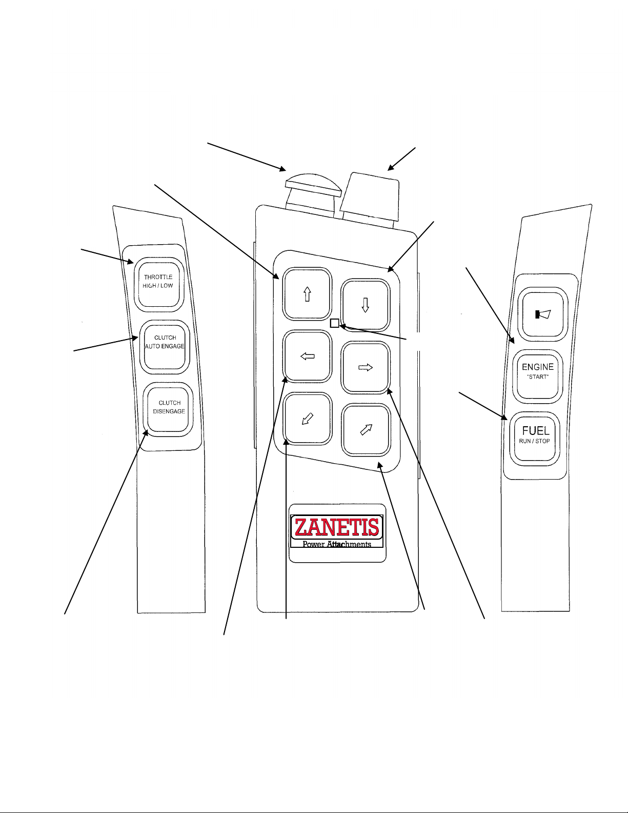
Emergency stop button
Key
Drum sideshift right
Drum sideshift left
Drum up
Drum down
Power indicator
REMOTE TRANSMITTER
RH3075 and RH4075
Throttle button
Clutch engage button
Clutch disengage button
Engine start button
Fuel button
Drum tilt right Drum tilt left
14
MAINTENANCE
Proper maintenance of the attachment will
result in longer life and the more produc-
tive and cost effective operation. There are
two basic categories of maintenance re-
quired, pick/holder replacement and
component lubrication. For proper opera-
tion, the picks should be checked each four
(4) hours and lubricated daily with a water
based emulsifying agent to ensure that they
can freely rotate in their holders.
BEFORE PERFORMING ANY MAIN-
TENANCE ON THE UNIT, PERFORM
THE MANDATORY SAFETY SHUT-
DOWN PROCEDURE.
WARNING
Pick/Holder Replacement
As regular use takes place, normal wear of
the carbide picks will occur with the outer
most picks wearing first. The pick tool in-
cluded with the cold planer should be use
to remove the picks from the cast holders.
In the event the pick tool is not available,
any hardened punch or tool allowing ac-
cess to the bottom of the holders can be
used.
IMPORTANT
Welder must be grounded directly to drum
during pick holder replacement or SEVERE
BEARING DAMAGE WILL RESULT.
A length of pipe with a 3/4 to 1 inch inside
diameter can be placed over the pick to pro-
tect it from a direct hit. Striking a small piece
of wood placed on the pick to absorb the
shock will prevent damage.
NEVER DRIVE THE PICK BY STRIK-
ING DIRECTLY ON THE END OF THE
PICK AS THIS CAN CAUSE THE PICK
TO CHIP AND CAUSE INJURY OR
CREATE SMALL STRESS FRAC-
TURES IN THE PICK, RESULTING IN
PREMATURE WEAR.
WARNING
ALWAYS WEAR SAFETY GLASSES
WHEN PERFORMING THIS OPERA-
TION. HARDENED TOOLS AND PICKS
CAN SHATTER CAUSING INJURY.
WARNING
The factory installed carbide pick chosen
for use is a general purpose pick as the
cold planer is designed for both asphalt
and concrete applications. Picks de-
signed for extended periods of concrete
cutting are available from the factory or
your dealer.
To prevent the picks from seizing in the
holders, the picks should be sprayed
with a lubricant at the end of each day.
This will break down the asphalt build up
in the holders and prevent premature
wear by allowing the picks to rotate in
the holders. Excess lubricant should be
caught in a collection pan and properly
disposed of.
If the pick remains in the holder beyond
its intended replacement point, it reduces
the cutting performance and will not pro-
tect the holder. Inspect the cutting drum
every hour of operation. Check the picks
and holders for wear. If the picks are
worn enough to indicate slight holder
wear, replace the picks.
NOTE: always disconnect the ECU, radio
receiver and master panel prior to any
welding.
See page 35 for these 3 locations.

15
Pre-delivery
•Install the muffler and air cleaner.
•Bolt attach plate to the sideshift frame. This may be a pin on
or quick attach style, depending on the factory order.
•Connect the battery terminals.
•Check and tighten any loose hardware.
•Check hydraulic, fuel, coolant and water levels. Add and required.
•Attach the RoadHog to the loader.
•Check all engine and drum functions, from panel and remote.

16
1. Turn engine control panel off. Press Red stop button on panel, do not reset.
2. Turn remote off and remove remote key.
3. Remove belt cover.
4. Loosen four engine cradle lock bolts two on each side of the cradle. Only loosen
slightly to allow cradle to slide up.
5. Loosen the jam nut on each adjuster bolt, two total.
6. Tighten the adjuster bolts. Adjust each bolt a turn at a time to keep the engine level.
7. Check tension with Gates Sonic Tension Meter as follows:
a)a)Connect Microphone to meter
b)b)Press POWER to turn meter on.
c)c) Press Hz to switch readout to Hertz.
d)d)Press MEASURE. Display should change to a horizontal line.
e)e)Hold the microphone about 1/2 inch away form belt at the midpoint of the
front span of the belt.
f) f)Strike the belt with hand.
g)g)Horizontal line on meter should change to a wavy line and read out the
frequency in Hertz.
Meter will not read a frequency less than 15Hz, so belt has to be fairly tight be-
fore the meter can read the frequency. High ambient noise levels can also pre-
vent the meter from reading the frequency.
8. Repeat steps 5 and 6 until belt tension on a 75 hp RoadHog is 41-42 Hz and 38-
39Hz with belts that have more than 100 hours.
9. Tighten jam nuts on both adjustment bolts and the lock bolts on the side of the
cradle
10.Start unit, engage clutch for 2-3 minutes. USE CAUTION WHEN BELTS COVER
ARE OFF!
11.Repeat steps 1 and 7 and recheck tension, adjust if necessary.
12.Reinstall all belts covers. Re-check belt tension at 100 hours thereafter, or if belt
slippage is detected. Belts with more than 100 hours should be set at 38-39Hz.
BELT TIGHTENING PROCEDURE
RH3075 and RH4075
17
Lubrication
Lubricate the deadshaft bearing at least
once a week..
The planetary gearbox contains syn-
thetic EP90 gear oil and should be half
full during operation. The planetary
gear oil should be drained and replaced
each year.
For pick maintenance, consult the main-
tenance section on page 14.
For additional information see the check
list on page 15.
BEFORE SERVICING THIS UNIT, THE
MANDATORY SAFETY SHUTDOWN
PROCEDURE MUST BE COMPLETED.
SEE “SAFETY” SECTION.
SERVICE
EXERCISE EXTREME CAUTION
DURING THIS OPERTION TO
PREVENT TIPPING OF THE UNIT.
Drum Removal
1. Perform mandatory shutdown proce-
dure with the cold planer adjusted to
the maximum depth. Ensure that
planer drum is sitting on a stable sur-
face and is chocked to prevent
movement.
2. Remove belt guard and loosen belt
idler, and remove belt.
3. Remove (8) planetary to chassis
bolts. Remove (4) input adapter
bolts. Remove (4) deadshaft bearing
to chassis bolts.
4. Lift cold planer off of drum using a
hoist or the wheel loader.
5. Reverse steps for reassembly.
IF THE DRUM DOES NOT REMAIN ON
THE FLOOR, LOWER THE PLANER,
SHUT THE ENGINE OFF, LOCK OUT
THE MASTER PANEL AND REVIEW
STEPS 1 THRU 5. DO NOT ATTEMPT
TO DISLODGE THE DRUM WHILE
THE PLANER FRAME IS IN THE
RAISED POSITION. NEVER PLACE
HANDS OR ANY PART OF YOUR
BODY IN, AROUND, OR UNDER THE
DRUM, AS IT MAY FALL CAUSING
SERIOUS INJURY.
WARNING WARNING
WARNING

18
Planetary Gearbox and Drive
Hub Removal
1. Remove the drum from the planer
chassis. ( see page 16 )
2. Remove (4) deadshaft nuts from the
left side of the drum and remove the
deadshaft weldment.
3. Remove (8) planetary stud nuts from
the right side of the drum.
4. Remove Planetary assembly from left
side of drum.
5. Reverse steps for reassembly.
COMPONANTS ARE EXTREMEMLY
HEAVY AND CAN CAUSE SERIOUS
INJURY OR DEATH IF PROPER LIFT-
ING TECHNIQUES ARE NOT USED.
WARNING

19
CHASSIS GROUP RH3075 and RH4075
1
2
6
4
7
2
8
2
11
1
12
1
13
1
15
2
16
2
18
1
19
2
22
4
26
6
32
2
34
4
41
4
28
8
2
17
3
1
4
1
5
1
9
210
1
14
1
17
1
23
4
25
627
2
28
11
35
8
21
12
24
2
30
12
36
24
37
4
38
4
39
2
24
2
40
12
33
6
40
8
20
4
29
4
31
4
40
2
37
8
40
640
11

20
ITEM QTY. PART NO. DESCRIPTION
1 2 106-0621 BUSHING, SHROUD BOLT
2 17 106-0831 PICK, ASPHALT (RP18)
3 1 106-1190 PLATE, WATERKIT COVER
4 1 106-1202 PLATE, BELTING RETAINER
5 1 106-1243 BELTING, RUBBER
6 4 106-1411 PIN WELDMENT
7 2 106-1668 CYLINDER, DEPTH RH
8 2 106-2501 LATCH ASSEMBLY, DRAW
9 2 106-2688 NUT, WING 5/16-18 PLATED
10 1 106-2691 COVER, BEARING ACCESS
11 1 106-2707 CHASSIS WELDMENT
12 1 106-2721 DEPTH SKID WELDMENT
13 1 106-2732 CHASSIS SHROUD WELDMENT
14 1 106-2735 WELDMENT, BREAKER BAR
15 2 106-2737 WELDMENT, WEAR SKID
16 2 106-2739 WELDMENT, WEAR SKID
17 1 106-2740 WELDMENT, PLANETARY SUPPORT
18 1 106-2742 PLATE, DEPTH SKID COVER
19 2 106-2743 PIN WELDMENT
20 4 HB025L0100A BOLT, 1/4-20 X 1.00 PLATED
21 12 HB031L0125A BOLT, 5/16-18 X 1.25 PLATED
22 4 HB038L0075A BOLT, 3/8-16 X 0.75 PLATED
23 4 HB038L0150A BOLT, 3/8-16 X 1.50 PLATED
24 4 HB050L0175A BOLT, 1/2-13 x 1.75 PLATED
25 6 HB063L0175A BOLT, 5/8-11 X 1.75 PLATED
26 6 HB063L0200A BOLT, 5/8-11 X 2.00 PLATED
27 2 HB063L0225A BOLT, 5/8-11 X 2.25 PLATED
28 19 HB063L0250A BOLT, 5/8-11 X 2.50 PLATED
29 4 HN025A NUT, 1/4-20 PLATED
30 12 HN031A NUT, 5/16-18 PLATED
31 4 HN038A NUT, 3/8-16 PLATED
32 2 HN050A NUT, 1/2-13 PLATED
33 6 HN063A NUT, 5/8-11 PLATED
34 4 HRRE125A RETAINING RING-EXTERNAL 1.25" DIA.
35 8 HW025NA WASHER, 1/4 NARROW PLATED
36 24 HW031NA WASHER, 5/16 NARROW PLATED
37 12 HW038NA WASHER, 3/8 NARROW PLATED
38 4 HW050NA WASHER, 1/2 NARROW PLATED
39 2 HW050WA WASHER, 1/2 WIDE PLATED
40 39 HW063NA WASHER, 5/8 NARROW PLATED
41 4 HW125NA WASHER, 1 1/4 NARROW PLATED
CHASSIS GROUP RH3075 and RH4075 ONLY
This manual suits for next models
1
Table of contents
Other RoadHog Planer manuals


