RoadHog CP12LF User manual

MANUAL
Operation
Maintenance
Service
Parts
Warranty
CP12LF
CP16LF
Serial number ___________________________
Date released for shipment _________________
RoadHog, Inc. 877-640-9975 www.roadhog-inc.com
PUBLICATION DATE: 03/25/11

2
INTRODUCTION
Thank you for your investment in Roadhog Inc. We are confident that you will find that
your Roadhog Inc is the easiest to operate, safest, most durable, and most efficient
attachment on the market.
Your Roadhog Inc is equipped with high performance, heavy duty components. To en-
sure that these components operate properly and effectively, this manual must be fol-
lowed. If any question regarding the operation or performance of this attachment ex-
ists, contact your Roadhog Inc dealer at once.
This manual contains safety instructions, guidelines for efficient operation, trouble-
shooting tips, and service maintenance procedures. When applicable, the terms “right”
and “left” are referenced from a sitting position and facing forward in the loader.
Throughout this manual, information is provided in boxes and highlighted by the word
IMPORTANT. This information should be read carefully. If complied with, it will improve
the operating efficiency of the unit and provide directives that will minimize costly
breakdowns and extend the life of the machine.
This warning symbol appears throughout this manual and
indicates that a safety hazard may exist if the information
given is not properly followed. When the warning signal is
encountered in the manual or on the unit, Be Alert! Your
personal safety is involved!
For more copies of this manual or the necessary safety decals, contact your Roadhog
Inc dealer.

3
TABLE OF CONTENTS
Page
SAFETY DECALS …………………………………………………………………………….4
SAFETY PRECATUTIONS …………………………………………………………………..5
MANDATORY SAFETY SHUTDOWN PROCEUDRE ……………………………………5
SAFETY ………………………………………………………………………………………..6
SETUP ………………………………………………………………………………………….7
OPERATION …………………………………………………………………………………..8
MAINTENANCE......…... ………………………………………………...…………………...9
SERVICE..…………………………………………………………………………………10-11
CHASSIS GROUP PARTS DRAWING……….………………………...………….....12-13
ATTACH GROUP PARTS DRAWING……….………………………...….……….....14-15
DRIVETRAIN AND DRUM PARTS DRAWING….…………..………………….......16-17
HYDRAULIC GROUP PARTS DRAWING...………………...…………...................18-19
DECAL GROUP PARTS DRAWING……….…………………………...…...……......20-21
HYDRAULIC SCHEMATIC……………………………...….…………………..…….. ….22
SPECIFICATIONS ……………………………………………...….………………………..23
WARRANTY ………………………………………………………...……………………….24
WARRANTY CLAIM FORM………………………………………..……………………… 25
NEW MACHINE DELIVERY REPORT…………………………………………………….26
OWNER INFORMATION CARD……………………………………………………………27
4
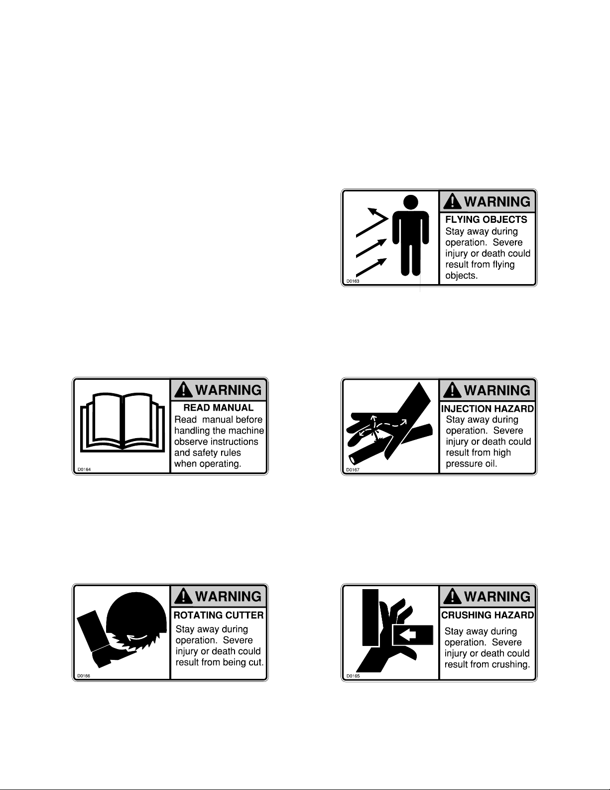
SAFETY DECALS
The safety decals existing on the
attachment should be clearly read-
able and always followed. The lo-
cation and description of the de-
cals is shown in the parts diagram.
The CRUSHING HAZARD decal
warns the operator and bystanders
to stay away during operation.
The ROTATING CUTTER decal
warns the operator and bystanders
to stay away during operation.
The READ MANUAL decal warns
the operator to read this manual
before operating the attachment.
The INJECTION HAZARD decal
warns the operator and bystanders
to stay away during operation.
The FLYING OBJECTS decal
warns the operator the operator
and bystanders to stay away dur-
ing operation.

5
SAFETY
PRECAUTIONS
ACCIDENTS ARE
PREVENTABLE WITH YOUR HELP
Understand and comply with applicable
laws and regulations.
Call local utilities before you dig.
Know the location of underground gas, water
and electrical lines.
Inspect area for holes, drop-offs, or unstable
ground.
Know the weight limitations of operating
surfaces and clearances.
Remember: Safe operation begins with the
operator.
BEFORE OPERATING THIS
EQUIPMENT, THE FOLLOWING
SAFETY INFORMATION SHOULD BE
READ AND UNDERSTOOD. IN
ADDITION, EACH INDIVIDUAL
WORKING WITH THE EQUIPMENT
SHOULD BE FAMILIAR WITH THE
SAFETY PRECAUTIONS
Exercise extreme caution when hitching
and removing the attachment, operating
with other workers present, and servic-
ing the unit.
Roadhog Inc makes operator safety a
priority when designing machinery. Ex-
posed moving parts are guarded when-
ever possible for safety. However, not
all moving parts can be shielded in or-
der to ensure proper operation. This op-
erator’s manual and safety decals on
the machine provide important safety
information when observed closely If
safety decals become difficult to read,
replace them immediately. (see “Safety
Decals”).
MANDATORY SAFETY
SHUTDOWN
PROCEDURE
BEFORE cleaning, adjusting, lubricating,
or servicing this unit, ALWAYS follow the
MANDATORY SAFETY SHUTDOWN
PROCEDURE:
1. Move the skid steer loader propulsion
control levers to the “neutral” position.
2. Move the loader throttle to the slow
idle position. Shut off the attachment
by shutting off the auxiliary and high
flow hydraulic output.
3. Lower the loader lift arms completely
roll the attachment forward so it is se-
curely resting on firm ground or the
shop floor.
4. Engage the loader park brake.
5. Shut the engine off, and remove the
ignition key.
6. Keep the key with you at all times
when working on the unit so no one
can start the engine without your
knowledge.
FAILURE TO FOLLOW THE
PROCEDURES BEFORE CLEANING,
ADJUSTING, LUBRICATING, OR
SERVICING THIS UNIT COULD LEAD
TO SERIOUS INJURY OR DEATH.
WARNING
WARNING

6
SAFETY
A careful operator is the best protection
against accidents. Most accidents involv-
ing operators of industrial equipment are
caused by failure to observe basic safety
precautions. Know the equipment and
worksite before you operate. Familiarize
yourself with the safety precautions listed
below.
THE FOLLOWING PRECAUTIONS
MUST BE OBSERVED FOR THE
SAFETY OF THE OPERATOR
AND/OR SERVICE PERSONNEL.
1. Read and observe all safety informa-
tion and decals on the skid steer
loader and attachment BEFORE
operating the unit!
2. Refer to the SAFETY section of your
skid loaders operator’s manual and
observe all safety recommendations
set forth in the manual.
3. When loading, keep attachment as
low to ramps & trailer as possible.
4. Always lower the loader arms fully
before leaving the skid steer seat.
NEVER CRAWL UNDER RAISED
LOADER ARMS.
5. BE SURE to raise the attachment
totally off the ground BEFORE side-
shifting.
6. CAREFULLY inspect ALL hydraulic
hoses and connections on a routine
basis; Always use a piece of card-
board when searching for leaks.
7. BE SURE to exercise the above MAN-
DATORY SAFETY SHUTDOWN pro-
cedure, BEFORE proceeding with any
work on the attachment.
NEVER USE YOUR HANDS AS
ESCAPING FLUID UNDER PRESSURE
CAN PENETRATE THE SKIN CAUSING
SERIOUS INJURY. IF HYDRAULIC
FLUID DOES PENETRATE THE SKIN,
SEEK IMMEDIATE MEDICAL
ATTENTION BY A DOCTOR FAMILIAR
WITH THIS TYPE OF INJURY OR
GANGRENE MAY RESULT.
NEVER ALLOW HANDS OR FEET
NEAR ANY WORKING PART OF THE
ATTACHMENT UNLESS THE
MANDATORY SAFETY SHUTDOWN
PROCEDURE HAS BEEN
COMPLETED.
WARNING WARNING
WARNING
WARNING

7
READ THIS ENTIRE MANUAL AS
WELL AS THE DECALS ON THE
ATTACHMENT BEFORE ATTEMPT-
ING ANY MAINTENANCE, SERVICE
OR SETUP OF THE UNIT.
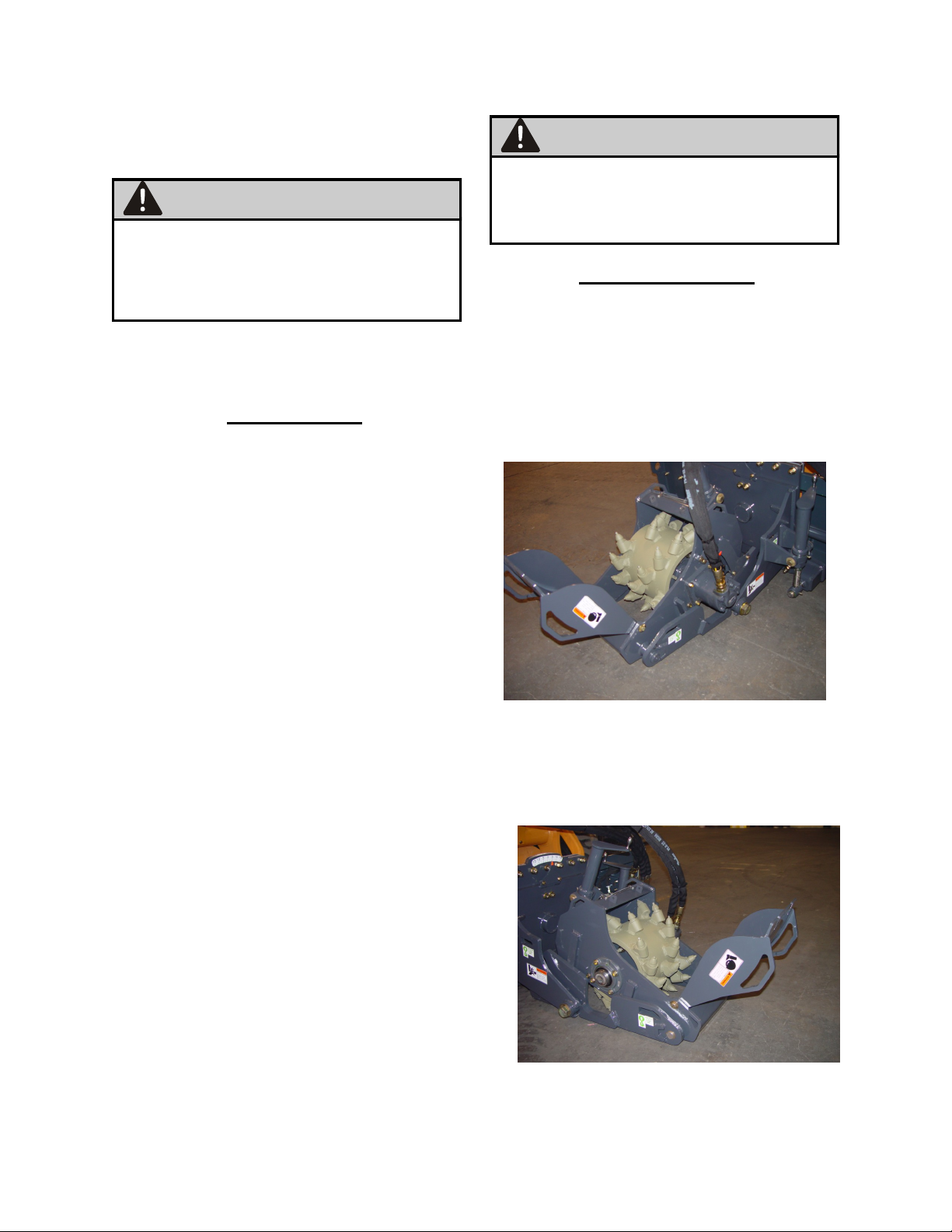
SETUP
Although the Roadhog Inc is supplied
fully assembled, some simple checks
should be performed before operation
begins.
Safety Decals
The safety decals existing on the attach-
ment should be clearly readable and al-
ways followed. The locations and de-
scriptions of the decals are shown in the
“Safety Decals” section.
Hydraulic Couplers
The planer has been shipped without
the 2 required hydraulic quick couplers.
Obtain correct brand and size and install
them on the hoses.
The CP12LF and CP16LF are Low Flow
Cold Planers which operates on the aux-
iliary flow of the skid loader. Since the
auxiliary flow is reversible, be sure to op-
erate the unit so the drum is spinning in
the correct direction. The drum should
spin in the direction the teeth are point-
ing.
Hoses / Fittings
Hydraulic fittings are used to connect
all attachment hoses. All fittings should
be tight and free of hydraulic leaks.
Hoses must be free of crimps or cuts
that might result in leakage. Check
your attachment before operation to
make sure all hose routings are kink-
free and allow for maximum movement
of all extend, lift/lower, and/or swing
motion required during normal opera-
tion.
Drum Assembly
For proper operation, picks must be
installed in every holder on the drum.
WARNING

8
OPERATION
The cold planer is a hydraulically
powered attachment intended for cutting
asphalt or concrete surfaces. The
performance of the attachment can vary
greatly depending upon how it is used
and operated. Therefore, the recom-
mended operating procedures contained
within this manual should be followed at
all times for maximum productivity.
Prior to operating the attachment, read
this entire manual. Follow all safety
guidelines in this manual and safety
decals on the unit. Make sure that all
guards, shields, and decals are in place
and in good condition prior to operation.
See page 23 for minimum flow
requirements for this model.
Insufficient hydraulic power will result in
poor performance. Check auxiliary high
flow per factory specifications
Attaching to Loader
To attach the unit to the loader, start the
loader engine and rotate the coupler out.
Pull both coupler levers up to the vertical
position. Move the machine forward and
pick up the attachment. Rotate the at-
tachment back and push both coupler
levers completely down. Make sure the
two wedges are completely down and
engaged. Be sure pins and latch handles
are secure before operating boom and
bucket. Always refer to operating instruc-
tions in the skidsteer manual.
In attaching the unit to the skid steer,
ensure that all hydraulic hoses are coupled
securely to the quick couplers. Two hoses
are to be connected, pressure & return.
IMPORTANT
All hoses should be free of kinks, cuts, or
abrasions for safe operation. Do not op-
erate if any hose are worn or damaged.
To Operate
1. Enter skid steer and fasten seat belt.
2. Make sure the area is clear of bystand-
ers and other workers.
3. Start the skid steer and engage the low
flow hydraulic circuit at idle.
4. Adjust the planers tilt & depth using the
manual jacks with the hand screw .
Sideshift as needed using the manual
diverter valve located on the sideshift
frame.
5. Move the throttle to the full rpm position.
and keep it there during the milling op-
erations. Lower the drum into the cut.
Move forward at a speed that will allow
the drum to efficiently without stalling.
NOTE. Milling speed will depend on tooth
condition, age and density of the material,
aggregate size and ambient temperature.
IMPORTANT

9
B E F O R E P E R F O R M I N G A N Y
MAINTENANCE ON THE UNIT,
P E R FO R M T H E M AN D AT O R Y
SAFETY SHUTDOWN PROCEDURE.
MAINTENANCE
Proper maintenance of the attachment
will result in longer life and the more
productive and cost effective operation.
There are two basic categories of
maintenance required, pick/holder
replacement and component lubrication.
For proper operation, the picks should be
checked each four (4) hours and lubri-
cated daily to ensure that they can freely
rotate in their holders.
Pick/Holder Replacement
As regular use takes place, normal wear
of the carbide picks will occur with the
outer most picks wearing first. The pick
tool included with the cold planer should
be use to remove the picks from the cast
holders. In the event the pick tool is not
available, any hardened punch or tool
allowing access to the bottom of the
NEVER DRIVE THE PICK BY STRIK-
ING DIRECTLY ON THE END OF THE
PICK AS THIS CAN CAUSE THE PICK
TO CHIP AND CAUSE INJURY OR
CREATE SMALL STRESS FRAC-
TURES IN THE PICK RESULT-
ING IN PREMATURE WEAR.
A length of pipe with a 25mm inside di-
ameter can be placed over the pick to
protect it from a direct hit. Striking a
small piece of wood placed on the pick to
absorb the shock will prevent damage.
The factory installed carbide pick chosen
for use is a general purpose pick as the
cold planer is designed for both asphalt
and concrete applications. Picks de-
signed for extended periods of concrete
cutting are available from the factory or
your dealer.
To prevent the picks from seizing in the
holders, the picks should be sprayed
with a lubricate at the end of each day.
This will break down the asphalt build up
in the holders and prevent premature
wear by allowing the picks to rotate in
the holders. Excess lubricant should be
caught in a collection pan and properly
disposed of.
If the pick remains in the holder beyond
its intended replacement point, it reduces
the cutting performance and will not pro-
tect the holder. Inspect the cutting drum
every hour of operation. Check the picks
and holders for wear. If the picks are
worn enough to indicate slight holder
wear, replace the picks.
WARNING
WARNING
WARNING
ALWAYS WEAR SAFETY GLASSES
WHEN PERFORMING THIS OPERA-
TION. HARDENED TOOLS AND PICKS
CAN SHATTER CAUSING INJURY.
IMPORTANT
Welder must be grounded directly to
drum during pick holder replacement or
SEVERE BEARING DAMAGE WILL
RESULT.
10
Lubrication
On the CP31.13 and CP41.13 cold
planer there are 5 grease points.
1. On the rear of the unit; two grease
zerks on the two sideshift tubes.
2. On the non motor side of the unit; a
bearing with a grease zerk.
3. Two grease zerks are on the depth
jack & tilt screw jack.
4. These 5 grease points should be
greased each day.
For pick maintenance, consult the
maintenance section on page 9.
BEFORE SERVICING THIS UNIT, THE
MANDATORY SAFETY SHUTDOWN
PROCEDURE MUST BE COMPLETED.
SEE “SAFETY” SECTION.
SERVICE
EXERCISE EXTREME CAUTION
DURING THIS OPERTION TO
PREVENT TIPPING OF THE UNIT.
Drum Removal
1. Perform mandatory shutdown pro-
cedure with the cold planer adjusted
to the maximum depth. Ensure that
planer drum is sitting on a stable
surface and is chocked to prevent
movement.
2. Disconnect the two hydraulic lines
connected to the motor.
3. Remove the four 1/2” motor bolts
that fasten the motor to the unit.
4. Remove the four 1/2” bolts that
fasten the bearing to the housing.
WARNING
WARNING

11
IF THE DRUM DOES NOT REMAIN ON
THE FLOOR, LOWER THE PLANER,
SHUT THE ENGINE OFF, REMOVE
THE IGNITION KEY AND REVIEW
STEPS 1 THRU 5. DO NOT ATTEMPT
TO DISLODGE THE DRUM WHILE
THE PLANER FRAME IS IN THE
RAISED POSITION. NEVER PLACE
HANDS OR ANY PART OF YOUR
BODY IN, AROUND, OR UNDER THE
DRUM, AS IT MAY FALL CAUSING
SERIOUS INJURY.
3. Remove the (4) nuts from the left side of
the drum and remove the motor assy.
4. Remove the cotter pin and nut on the
motor shaft and remove the hub.
5. Reverse steps for reassembly.
Drive Motor Removal
1. Remove the drum from the planer
chassis.
2. Remove (4) deadshaft nuts from the
right side of the drum and remove the
dead shaft.
WARNING
COMPONANTS ARE EXTREMEMLY
HEAVY AND CAN CAUSE SERIOUS
INJURY IF PROPER LIFTING TECH-
NIQUES ARE NOT USED.
WARNING
5. Lift cold planer chassis off of drum
using a hoist.
6. Reverse steps for reassembly.

12
CHASSIS GROUP (CHASSIS PARTS)
CP12LF and CP16LF
Cold Planer
3
1
4
1
8
1
13
1
14
2
22
2
28
2
29
2
30
2
1
2
27
2
12
1
2
2
5
1
9
1
10
1
11
1
23
3
24
2
25
2
26
2
31
2
46
3
15
1
16
1
17
1
18
1
19
2
20
1
21
4
32
2
7
2
2
4
37
2
41
4
42
2
41
4
41
4
37
2
37
2
39
2
44
4
35
3
39
6
6
1
33
2
34
4
36
2
38
8
40
4
43
2
45
2
40
4
40
4
36
2
36
2
7
2

13
CHASSIS GROUP (CHASSIS PARTS)
CP12LF and CP16LF
Cold Planer
CP12LF CP16LF
ITEM QTY PART NO. PART NO. DESCRIPTION
1 2 106-0504 106-0504 WHEEL WELDMENT
2 6 106-0585 106-0585 BEARING, DU 1.25 PIN X 1.25 WIDTH
3 1 106-0750 106-1628 CHASSIS WELDMENT
4 1 106-0765 106-1633 CHASSIS SHROUD WELDMENT
5 1 106-0771 106-0772 BELTING, RUBBER
6 1 106-0772 106-1642 PLATE, BELTING RETAINER
7 4 106-0773 106-0773 BUSHING, SHROUD BOLT
8 1 106-0774 106-0774 WELDMENT, CHASSIS GUSSET
9 1 106-0777 106-0777 WELDMENT, CHASSIS GUSSET
10 1 106-0780 106-0780 WELDMENT, DEPTH/TILT JACK
11 1 106-0787 106-0787 WELDMENT, DEPTH JACK MALE
12 1 106-0792 106-0792 PLATE, DEPTH INDICATOR
13 1 106-0793 106-1640 TUBE, WHEEL SPACER
14 2 106-0824 106-0824 PIN, SHROUD RETAINER WITH CABLE
15 1 106-3676 106-3676 SCREW, WING 3/8-16 X 2
16 1 106-3677 106-3677 PLATE, CABLE RETAINER
17 1 106-3678 106-3678 PLATE, CABLE RETAINER
18 1 106-3679 106-3679 CABLE, SHROUD RETAINER PIN
19 2 106-3680 106-3680 RING, SPLIT
20 1 106-3835 106-3836 PLATE, WATERKIT COVER
21 4 HB025L0100A HB025L0100A BOLT, 1/4-20 X 1.00 PLATED
22 2 HB038L0075A HB038L0075A BOLT, 3/8-16 X 0.75 PLATED
23 3 HB038L0150A HB038L0150A BOLT, 3/8-16 X 1.50 PLATED
24 2 HB044L0175A HB044L0175A BOLT, 7/16-14 x 1.75 PLATED
25 2 HB044L0200A HB044L0200A BOLT, 7/16-14 X 2.00 PLATED
26 2 HB044L0250A HB044L0250A BOLT, 7/16-14 X 2.50 PLATED
27 2 HB050L0175A HB050L0175A BOLT, 1/2-13 x 1.75 PLATED
28 2 HB050L0200A HB050L0200A BOLT, 1/2-13 X 2.00 PLATED
29 2 HB050L0225A HB050L0225A BOLT, 1/2-13 X 2.25 PLATED
30 2 HB050L0275A HB050L0275A BOLT, 1/2-13 X 2.75 PLATED
31 2 HB063L0175A HB063L0175A BOLT, 5/8-11 X 1.75 PLATED
32 2 HMSN08L150A HMSN08L150A SCREW, MACHINE
33 2 HMSNN06A HMSNN06A NUT, NO. 6 MACHINE SCREW
34 4 HN025A HN025A NUT, 1/4-20 PLATED
35 3 HN038A HN038A NUT, 3/8-16 PLATED
36 6 HN044A HN044A NUT, 7/16-14 PLATED
37 6 HN050A HN050A NUT, 1/2-13 PLATED
38 8 HW025NA HW025NA WASHER, 1/4 NARROW PLATED
39 8 HW038NA HW038NA WASHER, 3/8 NARROW PLATED
40 12 HW044NA HW044NA WASHER, 7/16 NARROW PLATED
41 12 HW050NA HW050NA WASHER, 1/2 NARROW PLATED
42 2 HW050WA HW050WA WASHER, 1/2 WIDE PLATED
43 2 HW063NA HW063NA WASHER, 5/8 NARROW PLATED
44 4 HWN08A HWN08A WASHER NO. 8 NARROW PLATED
45 2 HWN08LW HWN08LW LOCK WASHER, NO. 8 PLATED
46 3 HZ001 HZ001 ZERK, 1/4-28 STRAIGHT
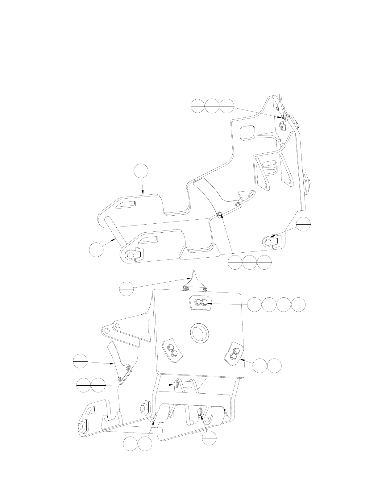
14
CHASSIS GROUP (DEPTH SKID PARTS)
CP12LF and CP16LF
Cold Planer
PARTS LIST
ITEM QTY . PA RT NO. DESCRIPTION
1 2 106-0500 PIN WELDMENT
2 2 106-0504 WHEEL WELDMENT
3 3 106-0534 PLATE, PIV OT SPACER
4 3 106-0535 PLATE, PIV OT RETA INER
5 4 106-0585 BEA RING, DU 1.25 PIN X 1.25 WIDTH
6 3 106-0606 PLATE, PIV OT SPACER
7 1 106-0769 PIN WELDMENT
8 1 106-0790 PIN, SIDESHIFT/LF JACK
9 1 106-0791 PLATE, DEPTH DECAL
10 1 106-0814 PLA TE, TILT INDICATOR
11 1 106-4161 DEPTH SKID WELDMENT
12 2 HB038L0100A BOLT, 3/8-16 X 1.00 PLA TED
13 2 HB038L0125A BOLT, 3/8-16 X 1.25 PLA TED
14 6 HB063L0300A BOLT, 5/8-11 X 3.00 PLA TED
15 4 HN038A NUT, 3/8-16 PLA TED
16 6 HN063A NUT, 5/8-11 PLA TED
17 5 HRRE125A RETAINING RING-EXTERNAL 1.25" DIA .
18 8 HW038NA WA SHER, 3/8 NARROW PLATED
19 12 HW063NA WASHER, 5/8 NARROW PLATED
1
2
11
1
7
1
12
2
13
2
2
2
8
1
9
1
17
3
4
3
10
1
14
6
15
2
18
4
15
2
18
4
19
12
5
4
17
2
3
3
6
3
16
6

15
CHASSIS GROUP (DEPTH SKID PARTS)
CP12LF and CP16LF
Cold Planer
CP12LF CP16LF
ITEM QTY PART NO. PART NO. DESCRIPTION
1 2 106-0500 106-0500 PIN WELDMENT
2 2 106-0504 106-0504 WHEEL WELDMENT
3 3 106-0534 106-0534 PLATE, PIVOT SPACER
4 3 106-0535 106-0535 PLATE, PIVOT RETAINER
5 4 106-0585 106-0585 BEARING, DU 1.25 PIN X 1.25 WIDTH
6 3 106-0606 106-0606 PLATE, PIVOT SPACER
7 1 106-0769 106-0769 PIN WELDMENT
8 1 106-0790 106-0790 PIN, SIDESHIFT/LF JACK
9 1 106-0791 106-0791 PLATE, DEPTH DECAL
10 1 106-0814 106-0814 PLATE, TILT INDICATOR
11 1 106-4161 106-4162 DEPTH SKID WELDMENT
12 2 HB038L0100A HB038L0100A BOLT, 3/8-16 X 1.00 PLATED
13 2 HB038L0125A HB038L0125A BOLT, 3/8-16 X 1.25 PLATED
14 6 HB063L0300A HB063L0300A BOLT, 5/8-11 X 3.00 PLATED
15 4 HN038A HN038A NUT, 3/8-16 PLATED
16 6 HN063A HN063A NUT, 5/8-11 PLATED
17 5 HRRE125A HRRE125A RETAINING RING-EXTERNAL 1.25" DIA.
18 8 HW038NA HW038NA WASHER, 3/8 NARROW PLATED
19 12 HW063NA HW063NA WASHER, 5/8 NARROW PLATED

16
ATTACH GROUP
CP12LF and CP16LF
Cold Planer
PARTS LIST
ITEM QTY . PA RT NO. DESCRIPTION
1 1 106-0522 WELDMENT, ATTACH
212 106-0532 PLATE, SIDESHIFT SPA CER
3 4 106-0533 PLATE, SIDESHIFT RETAINER
4 2 106-0589 PLATE, SIDESHIFT SPACER (PLA STIC)
5 1 106-0657 CYLINDER, SIDESHIFT
6 2 106-0773 BUSHING, SHROUD BOLT
7 1 106-0780 WELDMENT, DEPTH/TILT JACK
8 1 106-0787 WELDMENT, DEPTH JACK MALE
9 1 106-0790 PIN, SIDESHIFT/LF JACK
10 1 106-0808 WELDMENT, SIDESHIFT
11 1 106-0813 PLA TE, CYLINDER BRACKET
12 1 106-3676 SCREW, WING 3/8-16 X 2
13 1 106-3677 PLA TE, CABLE RETAINER
14 1 106-3678 PLA TE, CABLE RETAINER
15 1 106-3679 CABLE, SHROUD RETAINER PIN
16 2 106-3680 RING, SPLIT
17 2 HB050L0175A BOLT, 1/2-13 x 1.75 PLA TED
18 2 HB063L0175A BOLT, 5/8-11 X 1.75 PLA TED
19 12 HB063L0300A BOLT, 5/8-11 X 3.00 PLA TED
20 2 HN050A NUT, 1/2-13 PLA TED
21 12 HN063A NUT, 5/8-11 PLA TED
22 4 HRRE125A RETAINING RING-EXTERNA L 1.25" DIA.
23 4 HW050NA WA SHER, 1/2 NARROW PLA TED
24 26 HW063NA WA SHER, 5/8 NARROW PLA TED
25 3 HZ001 ZERK, 1/4-28 STRA IGHT
7
1
8
19
1
10
1
11
1
17
2
18
225
3
22
1
12
1
13
1
14
1
15
1
16
2
1
1
3
4
5
1
19
12
22
1
6
222
2
20
2
23
4
24
2
2
12
4
221
12
24
24

17
CP12LF CP16LF
ITEM QTY PART NO. PART NO. DESCRIPTION
1 1 106-0522 106-0522 WELDMENT, ATTACH
2 12 106-0532 106-0532 PLATE, SIDESHIFT SPACER
3 4 106-0533 106-0533 PLATE, SIDESHIFT RETAINER
4 2 106-0589 106-0589 PLATE, SIDESHIFT SPACER (PLASTIC)
5 1 106-0657 106-0657 CYLINDER, SIDESHIFT
6 2 106-0773 106-0773 BUSHING, SHROUD BOLT
7 1 106-0780 106-0780 WELDMENT, DEPTH/TILT JACK
8 1 106-0787 106-0787 WELDMENT, DEPTH JACK MALE
9 1 106-0790 106-0790 PIN, SIDESHIFT/LF JACK
10 1 106-0808 106-1626 WELDMENT, SIDESHIFT
11 1 106-0813 106-0813 PLATE, CYLINDER BRACKET
12 1 106-3676 106-3676 SCREW, WING 3/8-16 X 2
13 1 106-3677 106-3677 PLATE, CABLE RETAINER
14 1 106-3678 106-3678 PLATE, CABLE RETAINER
15 1 106-3679 106-3679 CABLE, SHROUD RETAINER PIN
16 2 106-3680 106-3680 RING, SPLIT
17 2 HB050L0175A HB050L0175A BOLT, 1/2-13 x 1.75 PLATED
18 2 HB063L0175A HB063L0175A BOLT, 5/8-11 X 1.75 PLATED
19 12 HB063L0300A HB063L0300A BOLT, 5/8-11 X 3.00 PLATED
20 2 HN050A HN050A NUT, 1/2-13 PLATED
21 12 HN063A HN063A NUT, 5/8-11 PLATED
22 4 HRRE125A HRRE125A RETAINING RING-EXTERNAL 1.25" DIA.
23 4 HW050NA HW050NA WASHER, 1/2 NARROW PLATED
24 26 HW063NA HW063NA WASHER, 5/8 NARROW PLATED
25 3 HZ001 HZ001 ZERK, 1/4-28 STRAIGHT
ATTACH GROUP
CP12LF and CP16LF
Cold Planer
18
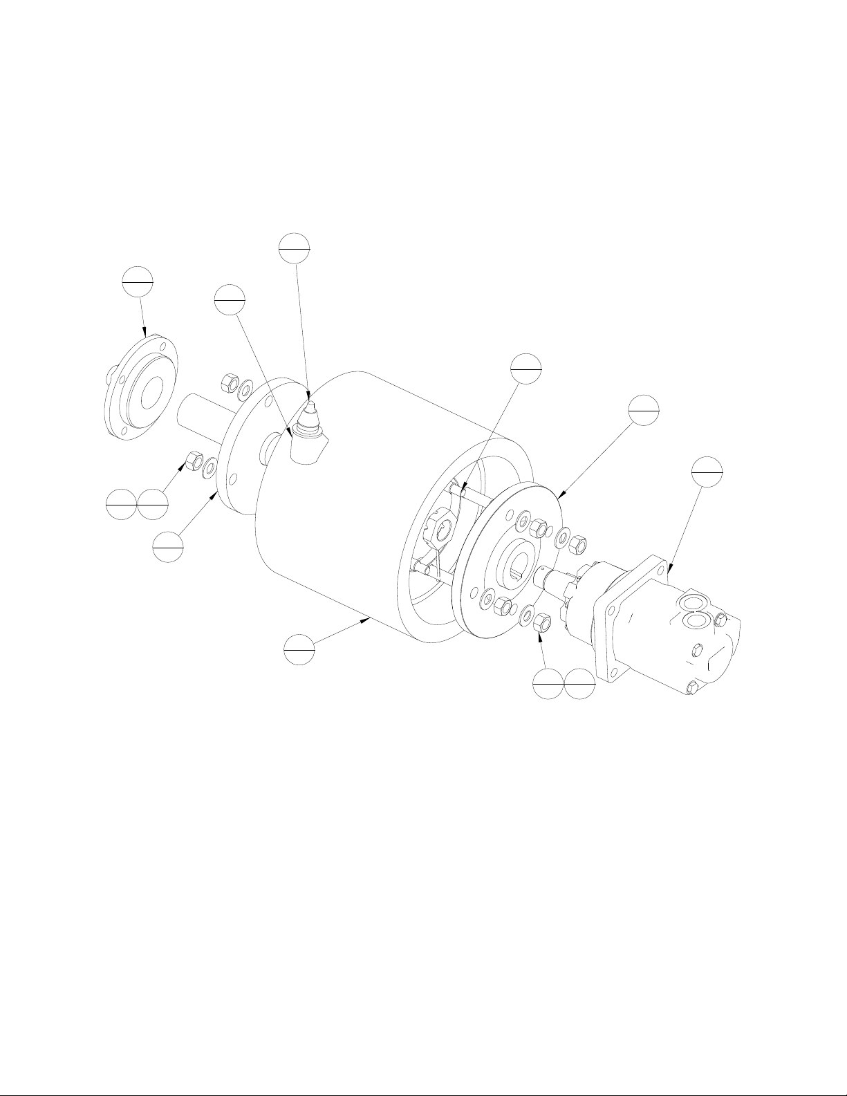
DRIVETRAIN and DRUM GROUP
CP12LF and CP16LF
Cold Planer
PARTS LIST
ITEM
QTY.
PART NO.
DESCRIPTION
1 8
106-0669 BOLT, 5/8-11 X 2.25 RND HD, RBD NECK
2 1
106-0794
MOTOR, EA TON 4K #110-1087
3 1
106-0795
ASSEMBLY, DRUM WITH PICKS & STUDS
4 1
106-0799
WELDMENT, MOTOR HUB
5 1
106-0800
WELDMENT, DEADSHAFT
6 1
106-0803
BEARING, DEADSHAFT
7 1
106-0831
PICK, A SPHA ULT (RP18)
8 1
106-0927
HOLDER, PICK
9 8
HN063A
NUT, 5/8-11 PLATED
10 8
HW063NA
WASHER, 5/8 NARROW PLATED
1
8
2
1
3
1
4
1
5
1
6
1
7
1
8
1
9
4
9
4
10
4
10
4

19
DRIVETRAIN and DRUM GROUP
CP12LF and CP16LF
Cold Planer
ITEM QTY PART NO. DESCRIPTION
1 8 106-0669 BOLT, 5/8-11 X 2.25 RND HD, RBD NECK
2 1 106-0794 MOTOR, EATON 4K #110-1087
3 1 106-0795 ASSEMBLY, DRUM WITH PICKS & STUDS
4 1 106-0799 WELDMENT, MOTOR HUB
5 1 106-0800 WELDMENT, DEADSHAFT
6 1 106-0803 BEARING, DEADSHAFT
7 1 106-3130 PICK, ASPHALT (RP18)
8 1 106-3140 HOLDER, PICK
9 8 HN063A NUT, 5/8-11 PLATED
10 8 HW063NA WASHER, 5/8 NARROW PLATED
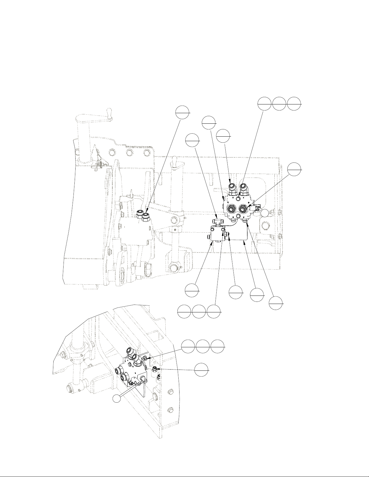
20
HYDRAULIC GROUP
CP12LF and CP16LF COLD PLANER
P A RTS LIS T
ITE M
Q TY .
P A R T N O .
D E S C R IP TIO N
1 1
1 0 6 -0 5 7 5
A S S E MB LY , C H E C K V A LV E
2 1
1 0 6 -0 8 2 8
A S S E M B LY , D IV E R TE R V A LV E
3 1
1 0 6 -1 2 4 7
P LA TE , V A LV E M O U N T
4 2
H B 025L0200A
BOL T , 1 /4 -2 0 x 2 .0 0 PL AT ED
5 2
H B 038L0150A
BOL T , 3 /8 -1 6 X 1 .5 0 PL AT ED
6 2
H B 038L0300A
BOL T , 3 /8 -1 6 X 3 .0 0 PL AT ED
7 4
H F12F5OLO
FITTIN G , S TR A IG H T 1 2 O R FS 1 2 S TO R
8 2
H F12V 5OLO
FITTIN G , E L B O W 12 O R FS 1 2 S TO R 4 5 D E G .
9 2
H F6-12F5O LO
FITTIN G , S TR A IG H T 6 O R FS 1 2 S TO R
10 4
H F6F5OLO
FITTIN G , S TR A IG H T 6O R FS 6S A E -O R B
11 1
H F6S 5O LO
FITTING, TEE -6 ST OR -6 ORF S -6 ORF S
12 2
H N 025A
NUT, 1 /4 -2 0 PL ATED
13 4
H N 038A
NUT, 3 /8 -1 6 PL ATED
14 4
H W 025N A
W A S H E R , 1/4 N A R R O W P LA TE D
15 8
H W 038N A
W A S H E R , 3/8 N A R R O W P LA TE D
4
2
7
2
11
1
10
2
1
1
2
1
3
1
6
2
8
2
9
2
7
2
5
2
10
2
12
2
14
4
13
2
15
4
15
4
13
2
This manual suits for next models
1
Table of contents
Other RoadHog Planer manuals


