manuals.online logo
Brands
  1. Home
  2. •
  3. Brands
  4. •
  5. Roadmaster
  6. •
  7. Automobile Accessories
  8. •
  9. Roadmaster Falcon 2 User manual

Roadmaster Falcon 2 User manual

Tow bar rated
at 6,000 pounds
ROADMASTER, Inc. 6110 N.E. 127th Ave. Vancouver, WA 98682 800-669-9690 Fax 360-735-9300 www.roadmasterinc.com
Owners and installers
must read the
installation instructions
and carefully note
the warnings!
Quick-disconnect parts list:
(2) quick-disconnects
(parts “A” and “B”)
(2) safety plates (“C”)
All mounting hardware
Figure 1
This tow bar is equipped with a “quick-disconnect” (or, “QD”) system.
Before connecting the tow bar to the vehicle, first install the compo-
nents of the QD system to the mounting brackets.
Note: the quick-disconnect system is not used with ROADMASTER
‘MS’ or ‘MX’ series mounting brackets. If the towed vehicle has MS or
MX brackets, proceed to “Connecting the tow bar.” The quick-disconnect
system should be reserved, however, for subsequent vehicles which may
not have these brackets.
1. First, attach the quick-disconnects (“QDs,” parts “A” and “B” in Figure
1) to the tow bar mounting brackets. Attach the QDs so that the vertical
pin on each is pointing up, as shown in Figure 1.
Attach part “A” on the passenger side, and part “B” on the driver's side.
Use the supplied ½" x 1¾" bolts, the two safety plates (parts “C”), and the
flat washers, lock washers and nuts, as shown in Figure 1.
Note: both QDs have an extra hole — “D” in Figure 1 — for safety cable
attachment. Mount parts “A” and “B” so that the “D” holes are to the out-
side.
Do not tighten any of the bolts — leave them loose for now — they will
be tightened later.
Use all mounting hardware and both safety plates. If all supplied
materials are not used, the quick-disconnects, the quick-disconnect
bases or other components may vibrate loose, which may cause prop-
erty damage, personal injury or even death.
2. Now, test-fit the crossbar — lower the crossbar (Figure 2) over the quick-
disconnects. The vertical pins at the top of both QDs should fit through
the top holes at the ends of the crossbar (Figure 2), and the vertical pins
at the bottom of the crossbar should fit through the lower holes on the
quick-disconnects (Figure 2).
3. Both quick-disconnects must be positioned so that the crossbar is cen-
tered to the front of the vehicle — measure the distance between the side
of one QD and the side of the mounting bracket it is attached to. Then,
make certain there is an equal distance between the other QD and the
other mounting bracket.
The quick-disconnects must be centered on the mounting brackets.
If they are attached too far to the left or the right, the tow bar will
not be centered on the towed vehicle, which will cause excessive tire
wear and other consequential, non-warranty damage.
4. Once the crossbar slides on and off easily, torque the four bolts to 75
ft./lbs.
Again, test-fit the crossbar over the QDs, to verify that the crossbar
slides on and off easily. If it does not, adjust the QDs again.
5. Both linch pins must be inserted through the upper holes in the vertical
pins in parts “A” and “B,” as shown in Figure 2.
Both linch pins must be locked. The rings are spring-loaded — they must
be snapped over the pins, with the curved side of the linch pin touching
the ring, in order to keep the QD bases secure.
Towing vibrations will force the linch pins out unless they are proper-
ly locked in place over the vertical pins on both quick-disconnects.
Failure to properly attach and lock both linch pins will result in
the losss of the towed vehicle, which may cause property damage,
personal injury or even death.
Figure 2
1
Installing the ‘quick-disconnect’ system
Installation Instructions
All specifications subject to change without notice
852282-10 04/12
Use caution when handling the tow bar — if your hands, fingers or
any part of your body are caught between moving components, they
can be pinched, cut or otherwise injured.
Connecting the tow bar
1. First, attach the tow bar quick-disconnects — refer to “Installing the ‘quick-
disconnect’ system” on page one.
Note: the quick-disconnect system is not used with ROADMASTER ‘MS’
or ‘MX’ series mounting brackets. Instead, the tow bar is connected directly
to the mounting bracket with the base pins and linch pins.
With this exception, the instructions below apply.
2. Drive the vehicle within three or three-and-a-half feet of the motorhome
hitch receiver. The vehicle does not have to be perfectly centered to the
hitch receiver, just close. Then, put the vehicle in gear (park), set the
emergency brake and chock one of the wheels.
3. With the tow bar in the folded position, insert the stinger into the motor-
home hitch receiver, and attach the stinger to the hitch receiver with the
hitch pin and clip.
Attach the tow bar so that the Autowlok buttons and the release latch
are pointing up. Components of the tow bar may be damaged if the
tow bar is attached with the release latch and the Autowlok buttons
pointing down.
4. Hold both tow bar arms firmly, and rotate them up, so that they are
vertical.
Never release the tow bar arms when they are in the vertical posi-
tion. The arms can fall and cause severe personal injury.
5. Push the release latch forward, to bring both arms down to a horizontal
position.
Standing to one side, swing both arms away from you. Then, align the
holes in the outermost arm with the holes in one of the tabs on the quick-
disconnect base.
Attach the tow bar arm to the quick-disconnect base with one of the base
pins (Figure 3). Attach the arm so that the head of the shoulder bolt (Figure
3) is facing up. Lock the base pin with a linch pin or optional padlock.
The linch pin must be locked. The ring on the linch pin is spring-loaded
— it must be snapped over the pin, with the curved side of the linch pin
touching the ring, in order to keep the base pin secure.
Both tow bar arms must be attached to the quick-disconnect bases
and locked with a linch pin. Towing vibrations will force the linch pins
out unless they are properly locked in place over the base pins on
both quick-disconnect bases.
Failure to properly install and lock both base pins will result in the
loss of the towed vehicle, which may cause property damage, personal
injury or even death.
6. Now, swing the other arm to the opposite side and connect it in the
continued on page three
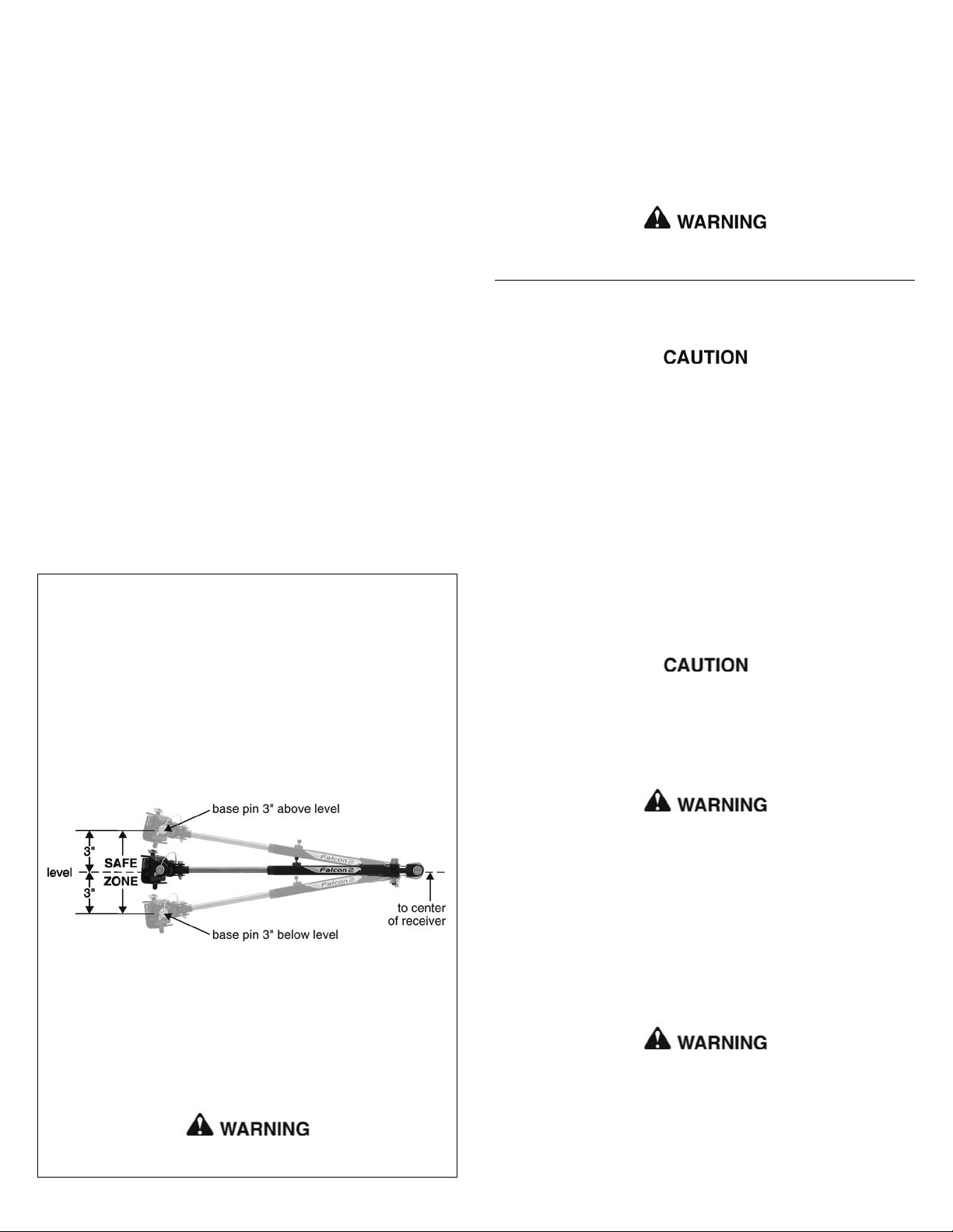
Towing with a motorhome-mounted tow bar which has an upward or
downward slope puts undue strain on the entire towing system. For that
reason, do not tow if the tow bar is not within the ‘Safe Zone’ — no
more than three inches above or below level.
Towing a vehicle with a tow bar that is not within the Safe Zone will
result in significant wear and tear on the tow bar and brackets, sig-
nificant wear and tear on the vehicle’s suspension and frame, and the
eventual failure of the towing system.
To determine if the tow bar is within the Safe Zone — first, con-
nect the motorhome and vehicle on level ground.
Next, measure the distance from the center of the motorhome receiver
down to the ground. Then, measure the distance from the center of one
of the base pins down to the ground.
Compare these two measurements. To be within the Safe Zone, they
cannot be more than three inches apart if the base pin is above or
below the motorhome hitch receiver.
If the tow bar is not within the Safe Zone, you must purchase a hitch
accessory to raise or lower the hitch receiver. ROADMASTER has three
accessories available — Hi-Low Hitches, Hi-Low Drops and Dual Hitch
Receivers — which will raise or lower the hitch receiver from two to 10
inches, depending on the model.
Towing with the tow bar more than three inches above or below level
will void the ROADMASTER warranty.
Failure to follow these instructions may cause property damage,
personal injury or even death.
2
• Stress to the owner that the tow bar must be within the ‘Safe Zone’
— no more than three inches above or below level. Towing with an out-
of-level tow bar will cause significant wear and tear on the tow bar and
mounting brackets, and on the towed vehicle’s suspension and frame.
(See the section titled “Stay within the ‘Safe Zone’” for further informa-
tion.)
• Show the owner how to properly operate the tow bar. Familiarize
yourself with the features of the tow bar. Demonstrate them to the owner,
and ask the owner to connect and disconnect the tow bar and other
components of the towing system, until the owner is comfortable with its
operation.
• The maximum towing capacity of this tow bar is 6,000 pounds. Advise
the owner to use 6,000 pound or higher rated safety cables when
towing. The safety cables must connect the towed vehicle to the towing
vehicle, frame to frame. In addition, the receiver hitch and all supple-
mentary towing equipment must be rated at no less than the weight of
the towed vehicle and all its contents.
• The tow bar must be attached to a bracket which is bolted to the
towed vehicle’s frame or unibody. In order to be towed, virtually all
vehicles require a tow bar mounting bracket that is connected to the
frame, unibody or chassis and extends beyond the bumper.
• Caution the owner to secure the tow bar with linch pins (or optional
padlocks) before towing. Unless the tow bar is secured to both vehicles
with all appropriate pins (or padlocks), the towed vehicle will detach.
• Read the instructions thoroughly before installing the ‘quick-dis-
connect’ (‘QD’) system and its components.
The tow bar will be attached to the QD system. If the QD system is not
properly aligned, centered and positioned on the towed vehicle, the tow
bar will not be centered on the towed vehicle, which may cause exces-
sive tire wear and other consequential, non-warranty damage.
• The installer must be sure that the vehicle is suitable or adaptable
for towing. Some vehicles must be equipped with a transmission lube
pump, an axle disconnect, driveline disconnect or free-wheeling hubs
before they can be towed. Failure to properly equip the vehicle will cause
severe damage to the transmission.
Installer’s safety checklist
Check the manufacturer’s instructions for the proper procedure(s) to
prepare the vehicle for towing.
• The installer must NOT use the tow bar as a ground for welding.
Connecting a ground to the ‘A-frame’ of the tow bar will cause current
to flow through the locking spring, which will detemper the spring and
destroy the locking mechanism.
• Under no circumstances should the tow bar be welded to the vehicle,
nor should any of the pre-punched mounting holes be altered. Any weld-
ing or altering of the tow bar will void the owner’s warranty.
Failure to follow these instructions may cause property damage,
personal injury or even death.
Stay within the ‘Safe Zone’
Connecting and disconnecting
Receiver extensions cause the towing system to swing much higher
and lower than towing systems without extensions. This enlarged
arc of motion creates excessive strain on the tow bar, brackets and
frame, which can cause the towing system to fail, causing property
damage, personal injury or even death.
Disconnecting the tow bar
1. Disconnecting the tow bar is essentially the reverse of connecting it.
Before you begin, always…
• …try to park on level ground, with the towed vehicle in line with the
motorhome; and
• …turn the towed vehicle's steering wheel until the front wheels are in
line with the motorhome.
This will eliminate most of the tension between the vehicles, allowing
for an easier disconnect.
2. Disconnect the electrical wiring harness, safety cables and any other
towing system accessories.
3. Press down on the Autowlok buttons to release the locking mecha-
nisms.
(Usually, one of the Autowlok buttons will require more pressure to
release. This is the arm that has the majority of the tension between the
two vehicles.)
Note: if the Autowlok button(s) will not release, turn the towed vehicle's
steering wheel as far as it can go to the left or right, then in the other
direction. Then straighten out the steering wheel until the front wheels are
in line with the motorhome.
Never use a hammer or mallet to disconnect the Autowlok buttons.
This will drive the plastic buttons down the shaft, preventing the lock
from releasing.
4. Put the towed vehicle in gear (park), set the emergency brake, and
chock one of the wheels.
Always put the towed vehicle in gear (park), set the emergency brake
and chock one of the wheels after releasing the Autowlok buttons,
and before removing the base pins. Failure to do so may result in a
‘runaway’ vehicle or may crush you between the towed vehicle and
the motorhome, causing property damage, personal injury or even
death.
5. Remove the base pins and store the tow bar on the motorhome by
reversing the connection procedure (under “Connecting the tow bar”).
ROADMASTER recommends replacing at least one of the linch pins with
a padlock (part number 301, 302 or 308) to prevent accidental release or
theft.
If you choose to store the tow bar on the back of the motorhome —
the bushings at the end of the tow bar arms can be warped by heat
from the exhaust. If the bushings are warped, the tow bar arms will
not slide easily, or they may not slide at all — it may be difficult to
connect or disconnect the tow bar, or you may be unable to connect
or disconnect it, until the bushings are replaced.
The tow bar can be stored on the motorhome with the arms rotated
to the left or the right. To avoid the possibility of damage to the bush-
ings, rotate the arms away from the engine exhaust.
Connecting the tow bar
continued from page two
same manner.
7. Attach the safety cables and plug in the electrical wiring cord, according
to the supplier’s instructions.
Before towing the vehicle, be sure the steering is unlocked, the trans-
mission is in the proper setting, and the emergency brake is released.
Remove the wheel chock.
Check the manufacturer’s specifications, the owner’s manual, or talk
to the installer for the proper towing procedures or requirement(s) for the
vehicle to be towed.
Do not tow the vehicle until the tow bar is attached with all pins or
padlocks. Unless the tow bar is secured to both vehicles with all ap-
propriate pins or padlocks, the vehicle will detach, which may cause
property damage, personal injury or even death.
When you drive away, steer briefly to the left and then to the right, to
extend, self-center and lock the tow bar.
Always stop at this time. Check the tow bar to ensure that both arms are
locked before assuming highway speed. Additionally, check the other com-
ponents of your towing system, to ensure that they are fully engaged.
Both tow bar arms must be locked before towing. If they are not,
the momentum of the towed vehicle will apply excessive force to the
tow bar arms and other components of the towing system, which
may cause the towing system to fail, resulting in property damage,
personal injury or even death.
The tow bar arms will not automatically lock if the Autowlok but-
tons are missing or damaged. While the arms can be locked manually
without the buttons, it creates the potential for tow system damage
and separation of the towed vehicle, should you forget to do so. For
this reason, replace missing or damaged Autowlok buttons immed-
iately.
Failure to follow these instructions may cause property damage,
personal injury or even death.
Do not tow a vehicle using tow bar mounting brackets, safety cables
or a hitch receiver rated less than the actual weight of the towed
vehicle.
If the brackets, safety cables, hitch receiver or any supplementary
towing equipment is not rated at the weight of the towed vehicle and
all its contents, it may fail during towing, causing property damage,
personal injury or even death.
If the motorhome hitch receiver has an extension, do not tow if the
tow bar is more than three inches out of level.
3
Figure 3
How to use safety cables
Safety cables are an integral part of your towing system. They are a
secondary safety device, required by law in many states. This section,
and the section titled “Proper installation of safety cables,” will acquaint
you with how to use them properly.
• The safety cables must connect the towing vehicle to the towed vehicle,
frame to frame.
•The safety cables must be rated at 6,000 pounds weight capacity per
pair, or higher. This is the maximum weight capacity of the tow bar — the
towed vehicle and all its contents cannot exceed 6,000 pounds.
• Pull the safety cables so that all the slack is at the motorhome. Make
sure there is enough slack in the cables at the motorhome to allow
for sharp turns — if there is not enough slack, the towing system will
be severely damaged when the motorhome turns a sharp corner.
continued on page four
For all towing systems…
• Wind the safety cables around the tow bar arms, and cross the safety
cables under the hitch receiver, as shown in Figure 4.
• Unscrew the connecting nuts on each quick link to connect the safety
cable loops. Finger-tighten the nuts firmly, until the loop is completely
closed, to secure the attachment. Do not substitute carabiners or other
devices for the quick links — the quick links are designed to hold the weight
of a towed vehicle; carabiners or other devices are not.
Option 1
If the tow bar mounting bracket is similar to the one shown in Figure 4
and the safety cables are long enough, connect the snap hook (or quick
link) to the safety cable anchor built into the mounting bracket.
Option 2
Some ROADMASTER tow bar mounting brackets with removable arms,
such as the one in Figure 5, use both a long safety cable and a short
safety cable on each side.
Each long safety cable runs from the towing vehicle to a quick link
attaching it to one of the quick-disconnects. This quick link is also an
attachment point for one of the short safety cables; another quick link
attaches the short safety cable to the mounting bracket.
Proper installation of safety cables
4
Figure 4
The Falcon 2 owner’s manual…
…contains additional illustrations to accompany these instructions, as
well as important safety information, the limited warranty and other infor-
mation to make your towing experience safe and pleasant.
Read the owner’s manual cover to cover before towing a vehicle.
How to use safety cables
continued from page three
•The safety cables must be the correct length…
•Make sure the cables are not too short — if you use a receiver hitch
extension or other equipment that extends the distance between the
towed vehicle and the motorhome, the standard cables may be too
short. If the cables are too short, the towing system will be severely
damaged when the motorhome turns a sharp corner.
(Safety cable extensions in a wide variety of lengths are available
from ROADMASTER.)
• Make sure the cables are not too long — the cables should not hang
down to the extent they may catch on obstructions, or drag on the
ground. This much slack could cause damage to the towing system,
the towed vehicle or the motorhome.
If the cables are too long, wrap the excess cable around the tow
bar to take up the slack. Make sure there is enough slack in the
cables at the motorhome to allow for sharp turns.
Damage caused by using safety cables of an incorrect length is not
covered under warranty.
•Always cross the cables under the hitch receiver, as shown in Figure
4 (above). In the unlikely event the tow bar separates from the
motorhome, crossing the cables will help prevent the tow bar from
dragging on the ground, which can cause the tow bar to “pole vault”
the towed vehicle.
• Some ROADMASTER tow bar mounting kits with removable arms
use two safety cables on each side. If two sets of safety cables are
required, both must be used. This is required by law. Refer to “Proper
installation of safety cables,” on this page, for further information.
Failure to follow these instructions may cause property damage,
personal injury or even death.
Option 1
(Safety cable tab is not
present on all brackets)
Option 2
Figure 5
The safety cables must be carefully routed so that they cannot
become pinched, frayed, scraped or otherwise damaged, and so they
will not drag when going over dips or low spots. Do not use the cables
if they show any signs of wear or damage — immediately discontinue
towing and replace the cables.
Failure to follow these instructions will result in cable failure, which
may cause property damage, personal injury or even death.
If the quick links are not completely tightened, with the loop closed,
the safety cables may detach. In the event of a towing system failure,
the towed vehicle will detach, which may cause property damage,
personal injury or even death.
If your towing system requires two sets of safety cables, always
use both the long and the short safety cables. Connect them as shown
in Figure 5. Otherwise, in the event of a towing system failure, the
towed vehicle will detach, which may cause property damage, personal
injury or even death.

Other manuals for Falcon 2

1

Other Roadmaster Automobile Accessories manuals

Roadmaster 751428 User manual

Roadmaster

Roadmaster 751428 User manual

Roadmaster 1007-2 RETRO User manual

Roadmaster

Roadmaster 1007-2 RETRO User manual

Roadmaster FuseMaster 76512 User manual

Roadmaster

Roadmaster FuseMaster 76512 User manual

Roadmaster Sterling User manual

Roadmaster

Roadmaster Sterling User manual

Roadmaster 917-3 User manual

Roadmaster

Roadmaster 917-3 User manual

Roadmaster 156-25 User manual

Roadmaster

Roadmaster 156-25 User manual

Roadmaster Invisibrake 8700 User manual

Roadmaster

Roadmaster Invisibrake 8700 User manual

Roadmaster BrakeMaster 9100 User manual

Roadmaster

Roadmaster BrakeMaster 9100 User manual

Roadmaster 1109-174 User manual

Roadmaster

Roadmaster 1109-174 User manual

Roadmaster 2120 Quick start guide

Roadmaster

Roadmaster 2120 Quick start guide

Roadmaster Tracker Original instructions

Roadmaster

Roadmaster Tracker Original instructions

Roadmaster REJ2000 User manual

Roadmaster

Roadmaster REJ2000 User manual

Roadmaster TOW DEFENDER 4800 User manual

Roadmaster

Roadmaster TOW DEFENDER 4800 User manual

Roadmaster Sterling All Terrain User manual

Roadmaster

Roadmaster Sterling All Terrain User manual

Roadmaster 031-5 User manual

Roadmaster

Roadmaster 031-5 User manual

Roadmaster BrakeMaster 9000 User manual

Roadmaster

Roadmaster BrakeMaster 9000 User manual

Roadmaster StowMaster ALL TERRAIN User manual

Roadmaster

Roadmaster StowMaster ALL TERRAIN User manual

Roadmaster BrakeMaster 9100 User manual

Roadmaster

Roadmaster BrakeMaster 9100 User manual

Roadmaster StowMaster 910003-10 Guide

Roadmaster

Roadmaster StowMaster 910003-10 Guide

Roadmaster 1139-143 User manual

Roadmaster

Roadmaster 1139-143 User manual

Roadmaster Hands-Free Bluetooth Car Kit VRBT330W Owner's manual

Roadmaster

Roadmaster Hands-Free Bluetooth Car Kit VRBT330W Owner's manual

Roadmaster Blackhawk 2 All Terrain User manual

Roadmaster

Roadmaster Blackhawk 2 All Terrain User manual

Roadmaster Even Brake 9400 User manual

Roadmaster

Roadmaster Even Brake 9400 User manual

Roadmaster 76515 User manual

Roadmaster

Roadmaster 76515 User manual

Popular Automobile Accessories manuals by other brands

Cruz 907-402 Assembly instructions

Cruz

Cruz 907-402 Assembly instructions

Thule XADAPT2 instruction manual

Thule

Thule XADAPT2 instruction manual

A.R.T. DI01 463 30 installation manual

A.R.T.

A.R.T. DI01 463 30 installation manual

TrailFX FX3003 manual

TrailFX

TrailFX FX3003 manual

Blue Ox BX1126 installation instructions

Blue Ox

Blue Ox BX1126 installation instructions

Sony X-7BT operating instructions

Sony

Sony X-7BT operating instructions

Denso KRISTAL user manual

Denso

Denso KRISTAL user manual

SUSPENZ 44-0143 manual

SUSPENZ

SUSPENZ 44-0143 manual

Audison FORZA AFBMW ReAMP 3 owner's manual

Audison

Audison FORZA AFBMW ReAMP 3 owner's manual

Ironman4x4 BB067 installation guide

Ironman4x4

Ironman4x4 BB067 installation guide

CrimeStopper CS-6604 installation manual

CrimeStopper

CrimeStopper CS-6604 installation manual

Thule Evo Raised Rail 710400 instructions

Thule

Thule Evo Raised Rail 710400 instructions

Trakm8 T10-Micro installation manual

Trakm8

Trakm8 T10-Micro installation manual

Yawarra ALIX quick start guide

Yawarra

Yawarra ALIX quick start guide

Mitsubishi Electric PEA-RP200WKA Service manual

Mitsubishi Electric

Mitsubishi Electric PEA-RP200WKA Service manual

Whelen Engineering Company HELS Lighthead installation manual

Whelen Engineering Company

Whelen Engineering Company HELS Lighthead installation manual

ECS Tuning Ziza ES2538942 Installation procedures

ECS Tuning

ECS Tuning Ziza ES2538942 Installation procedures

Pet Gear TL9166RF instruction manual

Pet Gear

Pet Gear TL9166RF instruction manual

manuals.online logo
manuals.online logoBrands
  • About & Mission
  • Contact us
  • Privacy Policy
  • Terms and Conditions

Copyright 2025 Manuals.Online. All Rights Reserved.