manuals.online logo
Brands
  1. Home
  2. •
  3. Brands
  4. •
  5. Roadmaster
  6. •
  7. Automobile Accessories
  8. •
  9. Roadmaster 3128-3 User manual

Roadmaster 3128-3 User manual

KIT# 3128-3
04/15/14
KS
R O A D M A S T E R,I N C.
Important
Note: this bracket will not accom-
modate the Guardian rock shield,
some models of the Tow Defender,
Stowaway or the StowMaster and
StowMaster All Terrain tow bars.
6
5
11
8
7
10
3
4
9
1
2
ROADMASTER, Inc. 6110 NE 127th Ave. Vancouver, WA 98682 360-896-0407 fax 360-735-9300 www.roadmasterinc.com
BASEPLATE KIT
INSTALLATION INSTRUCTIONS
Item Qty. Length Width Description Part #
1...........2.......... 4”..............1/2” ........ 1/2” X 4” BOLT .....................................................350105-00
2...........8............................1/2” ........ LOCK WASHER................................................... 350309-00
3...........6.......... 1 1/4”........1/2” ........ 1/2” X 1 1/4” BOLT ...............................................350094-00
4...........4............................1/2” ........ NUT...................................................................... 350258-00
5...........4.......... 1 1/4”........7/16” ...... 7/16” X 1 1/4” BOLT .............................................350074-00
6...........4............................7/16” ...... FLAT WASHER....................................................350345-00
7...........4............................7/16” ...... NUT...................................................................... 350256-00
8...........4............................7/16” ...... LOCK WASHER................................................... 350307-00
9...........1.......... 1.0............6mm ...... 6mm X 1.0 X 25mm BOLT ...................................355894-00
10.........1............................6mm ...... 6mm NUT............................................................. 355760-00
11 .........2........................................... DRAW PIN/SPRING PIN .....................................357035-00
KIT# 3128-3
04/15/14
KS
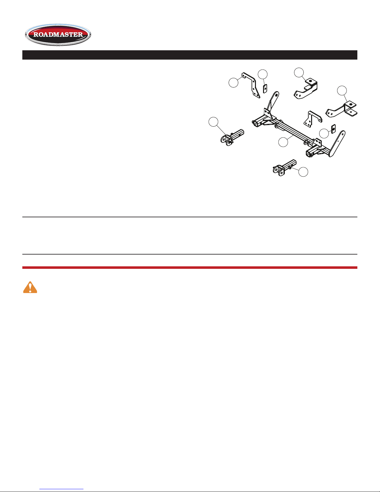
Item Qty. Part # Description
1...........1...........C-001019....... MAIN RECEIVER BRACE WELDMENT
2...........1...........C-001024....... DRIVER SIDE REAR BRACE WELDMENT
3...........1...........C-001025....... PASSENGER SIDE REAR
BRACE WELDMENT
4...........1...........A-000185....... 1/4" X 1 1/2" X 3" BACKING PLATE
5...........1...........C-001170....... 1/4" x 1 1/2" x 3" THREADED
BACKING PLATE
6...........2...........A-001673....... UPPER MOUNTING PLATE
7...........1...........C-001022....... DRIVER SIDE ARM BRACE WELDMENT
8...........1...........C-001023....... PASSENGER SIDE ARM BRACE WELDMENT
1
3
2
4
5
6
8
7
IMPORTANT: All braseplates must be assembled with all the bolts left loose for final adjustment and positioning (before
tightening) unless otherwise instructed. All bolts must be torqued for proper strength. If more than one bolt is used per
fastening point, the diagram may only show one.
• Use flat washers over all slotted holes • Use lock washers on all fasteners
• Installation of most baseplates requires moderate mechanical ap-
titude and skills. We strongly recommend professional installation by
an experienced installer.
• The installer must read the instructions and use all bolts and parts
supplied. Failure to do so could result in loss of the towed vehicle.
•Use Loctite® Red on all bolts used for mounting this bracket.
• Every 3,000 miles, the owner must inspect the fasteners for proper
torque, according to the bolt torque requirements chart on the last
page of these instructions. The owner must also inspect all mount-
ing points for cracks or other signs of fatigue every 3,000 miles.
Failure to do so could result in loss of the towed vehicle.
• The owner must check the vehicle manufacturer's instructions for
the proper procedure(s) to prepare the vehicle for towing. Some
vehicles must be equipped with a transmission lube pump, an axle
disconnect, driveline disconnect or free-wheeling hubs before they can
be towed. Failure to properly equip the vehicle will cause severe
damage to the transmission.
• If running changes were made by the vehicle manufacturer after this
kit was designed, some bolts or other fasteners in the hardware pack
may no longer be the correct size. It is the installer’s responsibility
to verify that the baseplate is securely fastened to the vehicle and fit-
ted with the correct hardware to account for these changes. Failure to
securely fasten the baseplate could result in loss of the towed vehicle.
• If the towed vehicle has been in an accident, it must be properly re-
paired before attaching the baseplate. Do not install the baseplate if
any structural frame damage is found. Failure to repair the damage
could result in the loss of the towed vehicle.
ROADMASTER Limited Warranty, including One-Year Conditional Warranty Text and Product Registration Card, in Carton.
• Roadmaster manufactures many styles of baseplates. If your base-
plate has removable arms, they must be removed before driving
the vehicle, unless the arms can be pinned or padlocked in place.
If not secured, the arms could vibrate out, resulting in non-warranty
damage or personal injury.
• Some motorhome chassis have such a tight turning radius that you can
damage your motorhome, towed vehicle, tow bar or baseplate while turn-
ing sharply. Before getting on the road, test your turning radius in
an empty parking lot. Turning too sharply could result in non-warranty
damage to towing system, motorhome and/or towed vehicle.
• Do not back up with the towed vehicle attached or non-warranty
damage will occur to your towing system, motorhome and/or towed
vehicle.
• The safety cables must connect the towing vehicle to the towed
vehicle frame to frame, with the cables crossed, with enough slack
for sharp turns. Refer to the cable instructions for proper routing.
Failure to leave enough slack in the safety cables, or failure to connect
the safety cables frame to frame, will result in the loss of the towed
vehicle.
• This kit is designed for use with ROADMASTER tow bars and ROAD-
MASTER adaptors only. Using this kit with other brands, without
an approved ROADMASTER adaptor, may result in non-warranty
damage or injury.
• Do not use this document for custom fabrication, as it may not show
all parts or structural components. Custom fabrication, or any attempt
to copy this baseplate design, could result in loss of the towed vehicle.
• Upon final installation, the installer must inspect the baseplate to
ensure adequate clearance, particularly around hoses, air condi-
tioner lines, radiators, etc., or non-warranty damage to the towed
vehicle will result.
• This baseplate is only warranteed for the original installation. In-
stalling a used baseplate on another vehicle is not recommended and
will void the warranty.
Failure to follow these instructions
can result in property damage,
personal injury or even death.
WARNING
BASEPLATE KIT
INSTALLATION INSTRUCTIONS
ROADMASTER, Inc. 6110 NE 127th Ave. Vancouver, WA 98682 360-896-0407 fax 360-735-9300 www.roadmasterinc.com
KIT# 3128-3
04/15/14
KS
2. Then, remove three plastic fasteners along the edge of each fender well (Fig.D).
3. Remove 18 plastic fasteners attaching the center splash shield to the fascia, fender liners and the subframe (Fig.E).
Then, remove the center splash shield (Fig.F).
4. Remove one plastic fastener (on each side) holding the fender liner to the
frame rail (Fig.G).
5. On each side, remove two 10mm nuts and one 10mm bolt holding the
fascia to the fender (Fig.H).
6. Also on each side, disconnect the plug for the side marker light, as well as
the plug for the fog light and the turn signal light (Fig.I).
7. Pull down and forward on each side to remove the fascia.
Fig.A
This is one of our MX series brackets, which allows the visible
front portion of the brackets to be easily removed from the
front of the vehicle (Fig.A and Fig.B). The bracket consists of a
main receiver brace, two lower braces, two upper braces, two remov-
able front braces and a hardware pack.
Before starting the installation, lay out the kit components in
order, as they will be used. This will give you a visual idea of how the
components work, and will also confirm that everything is present
and accounted for.
1. Important: please use all supplied bolts and parts and read
all instructions carefully before beginning this installation. The
majority of questions you may have can be answered within the
text, and proper installation will ensure safe and secure travel.
Now, begin the installation. Start by removing 10 plastic fasteners
across the top of the grill and the fascia (Fig.C).
Fig.B
Fig.C
Fig.D Fig.E
Fig.F
Fig.G Fig.H
Fig.I
BASEPLATE KIT
INSTALLATION INSTRUCTIONS
ROADMASTER, Inc. 6110 NE 127th Ave. Vancouver, WA 98682 360-896-0407 fax 360-735-9300 www.roadmasterinc.com
KIT# 3128-3
04/15/14
KS
All illustrations and specifications contained herein are based on the latest information available at the time of publication approval.
ROADMASTER, INC. reserves the right to make changes at any time without notice in material, specification and models or to discontinue models.
Fig.J
8. Remove two plastic fasteners, on each side (Fig.J), attaching the air deflectors to the bumper core, so that the air
deflectors can be pulled to one side (Fig.K).
9. Remove the bumper core — First, remove one 10mm bolt on the water bottle support bracket, on the passenger side
(Fig.L). Next, remove the four 13mm head nuts on each side which connect the bumper core to the frame horns (Fig.M).
Remove the bumper core (Fig.N).
Fig.K
Fig.L
Fig.M Fig.N
10. On the driver side, remove one 10mm bolt to remove the horn (Fig.O).
Fig.O
Fig.P
11. On the passenger side, use a file or a die-grinder to remove a metal tab on the subframe (Fig.P).
12. Fit the two lower braces to the subframe — Slide the braces between the frame and the subframe, and bolt each one
in place with one of the supplied ½" x 4" bolts and ½" lock washers through the existing holes in the subframe (Fig.Q).
Finger-tighten only at this time.
13. Attach the main brace — The brace fits between the radiator and the frame rail on the passenger side, and to the out-
side of the frame rail on the driver side. Bolt the main brace to the lower braces with two ½" x 1¼" bolts, lock washers and
nuts on each side (Fig.R).
Fig.Q Fig.R
BASEPLATE KIT
INSTALLATION INSTRUCTIONS
ROADMASTER, Inc. 6110 NE 127th Ave. Vancouver, WA 98682 360-896-0407 fax 360-735-9300 www.roadmasterinc.com
KIT# 3128-3
04/15/14
KS
All illustrations and specifications contained herein are based on the latest information available at the time of publication approval.
ROADMASTER, INC. reserves the right to make changes at any time without notice in material, specification and models or to discontinue models.
Fig.S Fig.T
14. Attach the side braces to the frame rails — Starting with the driver side, thread one of the supplied ½" x 1¼" bolts and
lock washers through the pre-drilled hole in the side brace, and through the existing hole in the frame rail (Fig.S). Next,
position the 1½" x 3" nutted backing plate over the bolt (Fig.S). Thread the bolt onto the backing plate. Finger-tighten only
at this time.
For the passenger side, thread a ½" x 1¼" bolt and lock washer onto the 1½" x 3" backing plate, and position it over
and into the pre-existing hole in the frame rail (Fig.T). The hole on this side brace is threaded. Use a ratchet or a ratchet-
ing wrench to thread the bolt onto the brace (Fig.U).
Fig.U
Fig.W
15. Level the bracket (Fig.V). Then, tighten the driver side brace bolt (Fig.V) to the torque specifications at the bottom of
these instructions.
16. Once the passenger side bolt has been threaded onto the side brace, use an air ratchet to tighten the bolt (Fig.W) to
the torque specifications at the bottom of these instructions.
17. Tighten all bolts to the torque specifications at the bottom of these instructions.
18. Attach the upper braces to the main brace — Slide both the driver side and the passenger side upper braces between
the hood latch support and the frame horn (Fig.X).
19. Once they are in position, secure
both of the upper braces to the main
brace with two 7/16" x 1¼" bolts,
flat washers, lock washers and nuts
(Fig.Y).
20. Trim the water bottle bracket
on the bumper core, using the black
mark in Figure Z as a reference.
Fig.X
Fig.Y
Fig.V
Fig.Z
2. Thread
the bolt.
1. Position the
nutted backing
plate.
BASEPLATE KIT
INSTALLATION INSTRUCTIONS
ROADMASTER, Inc. 6110 NE 127th Ave. Vancouver, WA 98682 360-896-0407 fax 360-735-9300 www.roadmasterinc.com
KIT# 3128-3
04/15/14
KS
Fig.AA
21. Remount the bumper core, sliding it through the end of both frame horns and through the upper braces (Fig.AA).
Apply thread lock to the outside lower 13mm head nuts which you removed in step 9, and bolt them back into place (Fig.
AA). Then, apply thread lock to the remaining nuts (three on each side) and bolt them in place. Torque all eight bolts to the
specifications at the bottom of these instructions.
22. Remount the horn — First, bend the alignment tab indicated in Figure BB. Bolt the horn to the bracket side brace,
through the existing hole, using the supplied 6mm x 1.0 x 25mm bolt and lock nut.
23. Trim both of the air deflectors to accommodate the main brace, reposition them, and reinstall the plastic fasteners
you removed in step 8. Trim the center splash shield as well, and then remount
the center splash shield (Fig.CC), reversing step 3.
24. Remove the grille insert (Fig.DD) or trim the inside section of the grille
insert so that the front receiver braces will fit through the grille.
25. Reinstall the fascia, reversing steps 1 through 2 and 4 through 7.
26. Fit the front bracket arms into the front receiver braces, and secure them in
place with the supplied 5/8" draw pins and spring pins.
27. Install the tow bar to the mounting bracket according to the manufacturer's
instructions. Attach the safety cables to the main receiver brace.
Fig.BB Fig.CC
Fig.DD
Install the
outside
lower
head
nut
first.
All illustrations and specifications contained herein are based on the latest information available at the time of publication approval.
ROADMASTER, INC. reserves the right to make changes at any time without notice in material, specification and models or to discontinue models.
BOLT TORQUE REQUIREMENTS
METRIC BOLTS
Thread Size Grade Plated / Unplated
12mm-1.25 ........8.8 ............70 ft./lb. 65 ft./lb.
12mm-1.5 ..........8.8 ............66 ft./lb. 61 ft./lb.
12mm-1.75 ........8.8 ...........65 ft./lb. 60 ft./lb.
14mm-2.0 ..........8.8 .........104 ft./lb. 97 ft./lb.
METRIC BOLTS
Thread Size Grade Plated / Unplated
8mm-1.0 ............8.8 ............20 ft./lb. 18 ft./lb.
8mm-1.25 .........8.8 ............19 ft./lb. 18 ft./lb.
10mm-1.25 ........8.8 ...........38 ft./lb. 36 ft./lb.
10mm-1.5 ..........8.8 ...........37 ft./lb. 35 ft./lb.
STANDARD BOLTS
Thread Size Grade Torque
5/16..................... 5........................... 13 ft./lb.
3/8....................... 5........................... 23 ft./lb.
7/16..................... 5........................... 37 ft./lb.
1/2....................... 5........................... 56 ft./lb.
5/8....................... 5......................... 150 ft./lb.
Note: The torque values represented below are intended as general guidelines. Torque requirements for specific applications may vary. Roadmaster does not warrant
this information to be accurate for all applications and disclaims all liability for any claims or damages which may result from its use.
BASEPLATE KIT
INSTALLATION INSTRUCTIONS
ROADMASTER, Inc. 6110 NE 127th Ave. Vancouver, WA 98682 360-896-0407 fax 360-735-9300 www.roadmasterinc.com

Other Roadmaster Automobile Accessories manuals

Roadmaster 1007-2 RETRO User manual

Roadmaster

Roadmaster 1007-2 RETRO User manual

Roadmaster 9700 User manual

Roadmaster

Roadmaster 9700 User manual

Roadmaster 2100 Quick start guide

Roadmaster

Roadmaster 2100 Quick start guide

Roadmaster Blackhawk 2 All Terrain User manual

Roadmaster

Roadmaster Blackhawk 2 All Terrain User manual

Roadmaster Sterling User manual

Roadmaster

Roadmaster Sterling User manual

Roadmaster 1149-107 User manual

Roadmaster

Roadmaster 1149-107 User manual

Roadmaster BrakeMaster 9000 User manual

Roadmaster

Roadmaster BrakeMaster 9000 User manual

Roadmaster Hands-Free Bluetooth Car Kit VRBT330W Owner's manual

Roadmaster

Roadmaster Hands-Free Bluetooth Car Kit VRBT330W Owner's manual

Roadmaster 751428 User manual

Roadmaster

Roadmaster 751428 User manual

Roadmaster FuseMaster 76512 User manual

Roadmaster

Roadmaster FuseMaster 76512 User manual

Roadmaster 1139-143 User manual

Roadmaster

Roadmaster 1139-143 User manual

Roadmaster Invisibrake 8700 User manual

Roadmaster

Roadmaster Invisibrake 8700 User manual

Roadmaster RLPF100 User manual

Roadmaster

Roadmaster RLPF100 User manual

Roadmaster 9300 Operating instructions

Roadmaster

Roadmaster 9300 Operating instructions

Roadmaster 917-3 User manual

Roadmaster

Roadmaster 917-3 User manual

Roadmaster Hands-Free Car Kit VRBT400 User manual

Roadmaster

Roadmaster Hands-Free Car Kit VRBT400 User manual

Roadmaster 155 User manual

Roadmaster

Roadmaster 155 User manual

Roadmaster REJ2000 User manual

Roadmaster

Roadmaster REJ2000 User manual

Roadmaster 156-25 User manual

Roadmaster

Roadmaster 156-25 User manual

Roadmaster Sterling ALL-TERRAIN 576 Original instructions

Roadmaster

Roadmaster Sterling ALL-TERRAIN 576 Original instructions

Roadmaster 1209-118 User manual

Roadmaster

Roadmaster 1209-118 User manual

Roadmaster Tracker Original instructions

Roadmaster

Roadmaster Tracker Original instructions

Roadmaster Guardian User manual

Roadmaster

Roadmaster Guardian User manual

Roadmaster FuseMaster 76511 User manual

Roadmaster

Roadmaster FuseMaster 76511 User manual

Popular Automobile Accessories manuals by other brands

Larson Electronics VMP-GMC-SRA-2019-1500 installation manual

Larson Electronics

Larson Electronics VMP-GMC-SRA-2019-1500 installation manual

INNOLIVING INN-305 user manual

INNOLIVING

INNOLIVING INN-305 user manual

Echomaster MM-70-UNI user manual

Echomaster

Echomaster MM-70-UNI user manual

Connects2 Vision CAM-FT6 user manual

Connects2

Connects2 Vision CAM-FT6 user manual

LAS 16143 operating instructions

LAS

LAS 16143 operating instructions

Menabo PROFESSIONAL AIRDYN C Fitting instructions

Menabo

Menabo PROFESSIONAL AIRDYN C Fitting instructions

Soundoff Signal Mpower PMPSABK004 manual

Soundoff Signal

Soundoff Signal Mpower PMPSABK004 manual

Whispbar K444W Fitting instructions

Whispbar

Whispbar K444W Fitting instructions

Abe CS8106 user manual

Abe

Abe CS8106 user manual

KC HiLiTES 9801/TYPE 1 Quick installation guide

KC HiLiTES

KC HiLiTES 9801/TYPE 1 Quick installation guide

Audiovox CCS-100 installation manual

Audiovox

Audiovox CCS-100 installation manual

Component Solution Services Verity SMW7J manual

Component Solution Services

Component Solution Services Verity SMW7J manual

Scosche CR1284 manual

Scosche

Scosche CR1284 manual

LAS 10326 operating instructions

LAS

LAS 10326 operating instructions

AAMP Global PAC RadioPRO RPK5-GM4101 manual

AAMP Global

AAMP Global PAC RadioPRO RPK5-GM4101 manual

Westin 65-1535 installation instructions

Westin

Westin 65-1535 installation instructions

Cruz Cargo SPro Assembly instructions

Cruz

Cruz Cargo SPro Assembly instructions

Thule 1323 instructions

Thule

Thule 1323 instructions

manuals.online logo
manuals.online logoBrands
  • About & Mission
  • Contact us
  • Privacy Policy
  • Terms and Conditions

Copyright 2025 Manuals.Online. All Rights Reserved.