ROAMER XTREME User manual


Roamer Batteries
Since founding Roamer in 2020, we have strived to create and deliver
exceptional products and service that give you the confidence to
venture further. The company has grown exponentially in the last three
years but our values and quality-first approach are still as strong as
they were on day one.
We’re committed to supporting o-grid lifestyles through the quality
manufacturing of superior LiFePO4 batteries, customer care and expert
support. We are confident that you’ll be delighted with the quality and
performance of your new Roamer battery but if you have any concerns
or questions, please get in touch straight away.
Our commitment is not only to our customers, but also the Vanlife,
Liveaboard and DIY solar communities as a whole. We’ve had
campervans for 12 years, we live and breathe this lifestyle and we love
hearing about your adventures after installing a Roamer battery.
Please don’t forget to tag @roamervans in your Facebook, Instagram,
Threads and TikTok posts so we can follow along with your journey.
We look forward to seeing you on the road someday soon...
Steve, Kate and the Roamer team
Roamer Batteries
Powering your O Grid Adventures
www.roamer.com

Safety
Roamer have taken every precaution to ensure that our batteries are
as safe as possible and give you complete peace of mind while using
our products. No battery is 100% safe however, and caution should
always be taken when handling or operating equipment containing, or
connected to, high-capacity energy storage devices.
LiFePO4 batteries should only be installed and operated by a
competent person. Please read this manual carefully and pay particular
attention to the recommended charge, discharge and temperature
limits as these may be dierent to the Battery Management System
(BMS) maximum limits.
Please read the separate Safety User Guide carefully. This contains
essential safety information and best practice on how to use your
battery. If you have any concerns or questions about safety, please do
not hesitate to contact Roamer at support@roamer.com

Contents
Quick start installation
What else is in the box?
What’s inside a Roamer battery?
Installation
Parallel and series connection
Discharging
Pre-charging your Inverter
Charging
Roamer BMS bluetooth app
Troubleshooting
Monitoring state of charge
Storing your battery
Disposing of your battery
Tech specs
Warranty
Returns & refund policy
Contact Roamer
5
7
7
9
11
12
12
13
15
19
21
23
23
25
26
27
28

5
Quick start guide
We’ve put together a summary of the installation
process to help you get started straight away.
Installation
Your battery should be installed in a location where it cannot be exposed to extreme
temperatures, moisture or vibration. If possible, install your battery, inverter and
chargers in the same area to keep cable lengths to a minimum. If installed in a
vehicle, fix the battery securely using brackets or ratchet straps bolted to the chassis.
Connecting cables
Our batteries are supplied with female M8 terminals and corresponding bolts. Cables
should be finished with copper tube M8 ring terminals, we do not recommend using
battery post adapters as these are not suitable for the sort of sustained high currents
possible with a Roamer battery.
You should also avoid connecting more than one cable to each battery terminal, if
you need multiple cables at the same voltage then you should install busbars and
connect one cable to each stud. Make sure all connections are tight and unable to
shake loose, we recommend using a torque setting of 10Nm.
Install the Roamer BMS app
Our SMART batteries can be monitored in real time using the free Roamer BMS app
for iOS or Android. During installation, make sure that you allow Bluetooth and GPS
connections when prompted or you will not be able to connect (don’t worry we do not
collect your data). You can use the app to check the state of charge, individual cell
voltages, current draw, and any fault codes.
Please note that the state of charge reading may be inaccurate until the battery has
completed 1-2 cycles, including a full discharge to 0% (10.8V for a 12V battery or
21.6V for a 24V battery). This does not aect the operation of the battery and you can
continue to charge the battery when the state of charge suggests it is full, as long as
the battery voltage does not exceed 14.2V.

6
Charging
For safety reasons your battery will be shipped at a low state of charge so you
should charge your battery on arrival. Battery chargers should be configured with a
LiFePO4 profile. Boost/absorption time should be 1 hour, and equalisation mode and
temperature compensation should be disabled. Do not leave the battery unattended
while charging and do not allow battery voltage to exceed 14.2V. Please read the
charging section of the user manual carefully.
Long term storage
If you are not ready to install your battery yet or you will not be using it for a while, we
recommend charging the battery to between 13.0V and 13.25V (40% and 80%) and
then isolating it completely from all external loads and chargers. If you really need to
keep the battery turned on when not in use and your charger has a storage mode,
you should set this to 13.2V. It is not necessary to trickle or float charge as Roamer
Batteries have an extremely low self-discharge rate of just 3% per month.
You should also monitor your battery voltage occasionally and ensure it does not
drop below 12.8V, if voltage drops below this then you will need to top up the charge.
You should fully cycle your battery every 6 months if storing for an extended period.
Recommended Charging Voltages for 12V and [24V] LiFePO4 Batteries
Absorption/Boost – 14.2V [28.4V]
Float – 13.5V [27.0V]
Storage – 13.2V [26.4V]

7
What else is in the box?
• 2x M8x16mm stainless steel terminal bolts with captive washers
• 2x M8x10mm stainless steel terminal bolts with captive washers
• Battery factory test report
• User manual
• Safety Instructions
• Warranty terms and conditions
Please retain all documentation for future reference, but if you misplace them or
decide to recycle them then digital versions are also available on our website.
If any of these parts are missing, please contact us at support@roamer.com or call
our technical support team on (+44) 113 8878335 to arrange a replacement.
What’s inside a Roamer battery?
Roamer only use the highest quality components including factory original grade
A cells purchased directly from top tier manufacturers. We also provide cell serial
numbers for complete transparency and traceability. These are logged by Roamer
before shipping and are printed on the factory test sheet and via the QR code on the
battery case. This can be scanned to view the serial numbers.
Our custom high-power BMS and Roamer app give you complete protection and
visibility of what is going on inside your battery, and our premium balancer circuitry
helps keep all cells perfectly in line for a long and healthy life.
Your battery is professionally constructed using precision engineered brackets, CNC-
cut epoxy insulation board and high-capacity busbars and cables. We take immense
pride in the quality and reliability of our batteries, but we also make them fully
serviceable in case of problems or if an upgrade becomes available. While the case
can be opened for repairs and upgrades, please do not try to do this yourself without
speaking to Roamer Technical Support as you will invalidate your warranty.


9
Installation
Your battery can be installed in any orientation, including on its side. If installing
in a vehicle, then it is crucial that the battery is securely fixed down so it cannot
slide while the vehicle is moving. It must also be accessible so it can be removed
or disconnected in an emergency. We recommend having tools readily available
including cable cutters and a socket wrench of the correct size.
You should install the battery in a way that avoids exposing it to extreme hot or
cold temperatures and facilitates an even temperature distribution across the
whole battery pack. If installing the battery on the floor of a vehicle, you should fit
insulation and/or an air gap between it and the floor’s surface as this will prevent
cold bridging from the metal sub-floor. Our XTREME series are extremely tolerant of
low temperatures and can be charged quickly even in sub-zero temperatures but
caution should still be taken when used in extremely low temperature environments,
particularly where the batteries are not installed in an insulated location.
Your battery comes supplied with M8 bolts, flat washers, and spring washers. You
should therefore terminate your battery cables with copper tube ring terminals with
an 8mm hole. The cable terminal should be placed flat, directly onto the battery
terminal. Next place the flat washer, then the spring washer, then feed the bolt
through this stack. The bolts should be tightened to a torque setting of 10Nm. Loose
connections can introduce contact resistance which will cause the termination to heat
up during high current flow. This is a serious fire risk and must be done correctly. If
you are upgrading from a lead acid battery with clamp posts, we recommend
re-terminating your cables as described above, instead of fitting screw-in battery
posts. These are not appropriate for the high current flow possible with your battery.
You should only have one main cable connected to each battery terminal bolt. If
you have multiple chargers and other components to connect, then you should use
busbars or a distribution system. Too many cable connections on one bolt adds
excessive resistance, which under high current flow can become extremely hot. You
should ensure that this risk is minimised by only installing one ring terminal on a
single stud or terminal. Shifting any complex connection points away from the battery
reduce the risk of starting a battery fire.
Be very careful not to short-circuit the positive and negative terminals. The resulting
current surge could cause damage to the battery and any external components it
flows through. Double check the polarity of the battery and any equipment before
connecting them. Connecting a battery the wrong way around can cause irreparable
damage to the battery and any components connected to it.

10

11
Parallel and series connection
Multiple batteries can be wired together in parallel or series to create higher capacity
or voltage battery banks.
Parallel configuration is achieved by connecting the positive terminals of multiple
batteries together to create one common positive node and connecting the negative
terminals together to create one common negative node. The capacities and
maximum current outputs are added together but the voltages are not. For example,
two 200XTREME batteries in parallel will have a total capacity of 400Ah, a peak
delivery current of 500A, and a nominal system voltage of 12.8V.
Series configuration is achieved by connecting the positive terminal of one battery to
the negative terminal of another. The negative terminal of the first battery is used as
the system negative node, while the positive terminal of the second battery is used
as the system positive node. The voltages are added together but the capacities
and maximum current outputs are not. Two 200XTREME batteries in series will have
a total capacity of 200Ah, a peak delivery current of 250A, and a nominal system
voltage of 25.6V.
• We do not recommend connecting more than 4 batteries in parallel. Where
possible, a single higher capacity battery is usually safer and easier.
• We do not recommend connecting more than 2 batteries in series. Roamer also sell
24V and 48V batteries if required.
• All batteries must be fully charged and allowed to settle to within 0.05V of each
other before connecting in series.
• Batteries in parallel series must be the same brand, voltage, capacity and age.
• If connecting two batteries in parallel, you should take the positive cable to loads/
chargers from battery A and the negative cable from loads/chargers to battery B.
This helps to evenly distribute loads across both batteries.
• If connecting more than two batteries in parallel, you should connect each battery
to a busbar rather than connecting together directly. If you use this method then it is
vital you use connecting cables that are exactly the same length.

12
Discharging
Your Roamer battery can deliver extremely high continuous discharge currents and
allows the operation of high-power appliances either directly at DC 12V or 24V, or at
mains AC voltages (230V in the UK and mainland Europe) via an inverter. You should
ensure that connecting cables and the main battery cables are sized appropriately
for the loads, and the correct size and type of protective fuse is used. Please refer to
the inverter manual for guidance. Recommended maximum inverter sizes for each
Roamer battery model are given in the table below.
Pre-charging your Inverter
Inverters contain large internal capacitors which, when connected to a LiFePO4
battery for the first time can draw a very high inrush current of up to 4000A. This
surge current can damage a LiFePO4 battery BMS and other connected equipment
and is also potentially dangerous. The solution is to pre-charge the capacitors in the
inverter. We recommend that any inverter larger than 1500VA should be pre-charged
on first connection. This also applies if the battery has been isolated from the inverter
for prolonged periods of time.
Pre-charging involves slowing down the inrush current, thereby filling the capacitors
with charge in a steady and controlled way. There are a few ways to do this: the
traditional method is to hold a high-power resistor between the battery and the
inverter for 30 seconds, you can then remove the resistor and connect the cable
normally. We recommend a 8Ω 50W resistor for 12V inverters and 16Ω 100W resistor
for 24V inverters. The other method is to isolate the battery and use a fixed current
power supply (or charger) to energise the DC system. For example, you could use a
DCDC charger powered by an engine alternator.
Please note that your Roamer battery BMS includes a surge current protection
feature, if you attempt to connect the inverter without pre-charging then your battery
may enter full protection mode with an error code of ASCD. See the troubleshooting
guide at the end of this manual for tips on how to reset your battery if this happens.
100XTREME 200XTREME 24-100XTREME
Maximum BMS discharge rate [A] 250 250 250
Maximum recommend discharge current [A] 100 200 100
Maximum recommended inverter power [VA] 1600 2500 3000

13
Charging
You can charge your Roamer battery in a number of dierent ways:
• Using mains or a generator via a multi-stage AC-DC charger or an inverter-charger
• Using solar panels or a wind turbine via a MPPT charge controller
• Using a vehicle alternator via a DC-DC charger
Whichever method you choose, it is important to choose a charger model with
appropriate LiFePO4 charge profile. The Roamer BMS will automatically prevent you
from overcharging the battery by disabling charging when the high voltage threshold
is reached. This is an emergency protection however and should not be relied upon
as a substitute for an appropriate LiFePO4 charger.
The ideal charge profile for your battery involves bulk charging at a constant current
up to a target voltage of 14.2V and then stopping. The active balancer in your Roamer
battery means an absorption or float stage is not required although we recommend
a short absorption period (up to 1 hour) to ensure battery is charged to its absolute
maximum capacity.
Most multistage chargers have bulk, absorption and float stages that can be
configured via a Bluetooth app or selector switch. Some brands use dierent
terminology, but the functions are the same. You should choose the profile that most
closely matches the parameters given below, with ideal and acceptable charge
voltages also shown. Make sure to double any voltages given for 24V batteries, or
refer to the datasheet for your particular product.
• Bulk/absorption/boost/target voltage: 14.2V (13.9V to 14.4V is ok)
• Float/storage voltage: 13.5V or o (13.2V to 13.6V is ok)
• Absorption time: 1 hour (0 to 2 hours is ok)
• Equalisation: O (or set equal to bulk voltage with equalisation time 0)
• Temperature compensation: O
You should have at least one charger in your system that is able to ‘wake up’ a lithium
battery in low voltage protection mode. If you run down your battery to the low
voltage cuto point, then the BMS will enter protection mode to prevent any further,
damaging, discharge and will show 1-3V across the terminals. Many lead acid (and
even some lithium-ion) chargers cannot detect the battery in this instance and will not
send a charge. Therefore, a charger (or a power supply) that works in this situation
will be required or you could end up without power or a way to recharge the battery.

14
Note that almost all Victron branded chargers have a preset charge profile called
‘Smart Lithium LiFePO4’ with a charge profile that matches the ideal voltages shown.
They will also wake up a lithium battery in low voltage protection mode. This is why
we recommend Victron chargers but there are lots of other great brands out there
that work well too.
Low temperature charging
Unlike standard LiFePO4 batteries, Roamer XTREME series be charged at
temperatures below 0°C without causing permanent damage to the cells. Roamer
batteries include a low temperature charge protection function in the BMS which
will prevent you charging once the internal battery temperature reaches the safe
limit. For XTREME series products the discharge limit is -40°C, and the charge limit is
-30°C. This protection will remain in place until the temperature rises back above the
release temperature to prevent charging and discharging right on the threshold. Due
to XTREME series batteries using smaller, less bulky cyclindrical cells than SMART
series batteries, it takes less time for the internal temperature to match the ambient
temperature, and for all cell temperatures to equalise. Caution should still be taken as
large batteries still have a significant mass to change temperature.
We do not recommend applying an external source of direct heat to either the cells or
the battery casing. If you need to warm the battery then gently heat the air around the
battery, not the battery itself. This is another reason leaving an air gap underneath the
battery is a good idea.
To maintain a long and healthy life for your battery and to minimise safety risks, you
should also reduce charge currents according to the battery temperature. Please pay
attention to the recommended charge currents are given below, failure to adhere
to this advice could lead to premature battery failure and will increase the risk of a
battery fire.
100XTREME 200XTREME 24-100XTREME
BMS charge current limit [A] 250 250 250
Maximum charge current at 25°C [A] 100 200 100
Maximum charge current at 10°C [A] 100 200 100
Maximum charge current at 5°C [A] 100 200 100
Maximum charge current at 0°C [A] 50 100 50
Maximum charge current at -20°C [A] 20 40 20

15
Roamer BMS app
The Roamer BMS app allows you to monitor your battery in real time,
showing state of charge, current, voltages and protection warnings
Getting started
The Roamer BMS App is available to download for both iOS and Android on the
AppStore and Play Store. It can be installed in iOS 10.0 or above and Android 4.3 or
above. Bluetooth version 5.0 or above with BLE is required. When installing the app,
you MUST accept all security permissions, this includes GPS on Android phones. We
do not collect any customer data.
The Roamer BMS can only connect to one device at a time, if you install the app on
multiple devices then you must force close and disconnect the app on the first device
before attempting to connect on the second device. If you do not do this, then the
battery will not show up in the available devices list.
After opening the app, find your Roamer battery from the list (it will have the same
name as your serial number shown on the original box and the case label). It can
take up to 10 seconds for your battery to appear, and the same again after clicking to
connect.
BMS tips
If your battery is in protection mode and shows any of the error codes above, you
should stop using and isolate the battery immediately. Investigate what has caused
the issue, then rectify the situation before reconnecting the battery.
If your battery has discharged below its safe voltage, the Bluetooth module may
not function correctly. If you cannot detect the battery over Bluetooth, immediately
disconnect the battery from any load and refer to our troubleshooting guide.
If you are unsure, please see the troubleshooting guide at the end of this manual, or
email support@roamer.com with screenshots of each page of the Roamer BMS App
and we will help you resolve it.
16

17
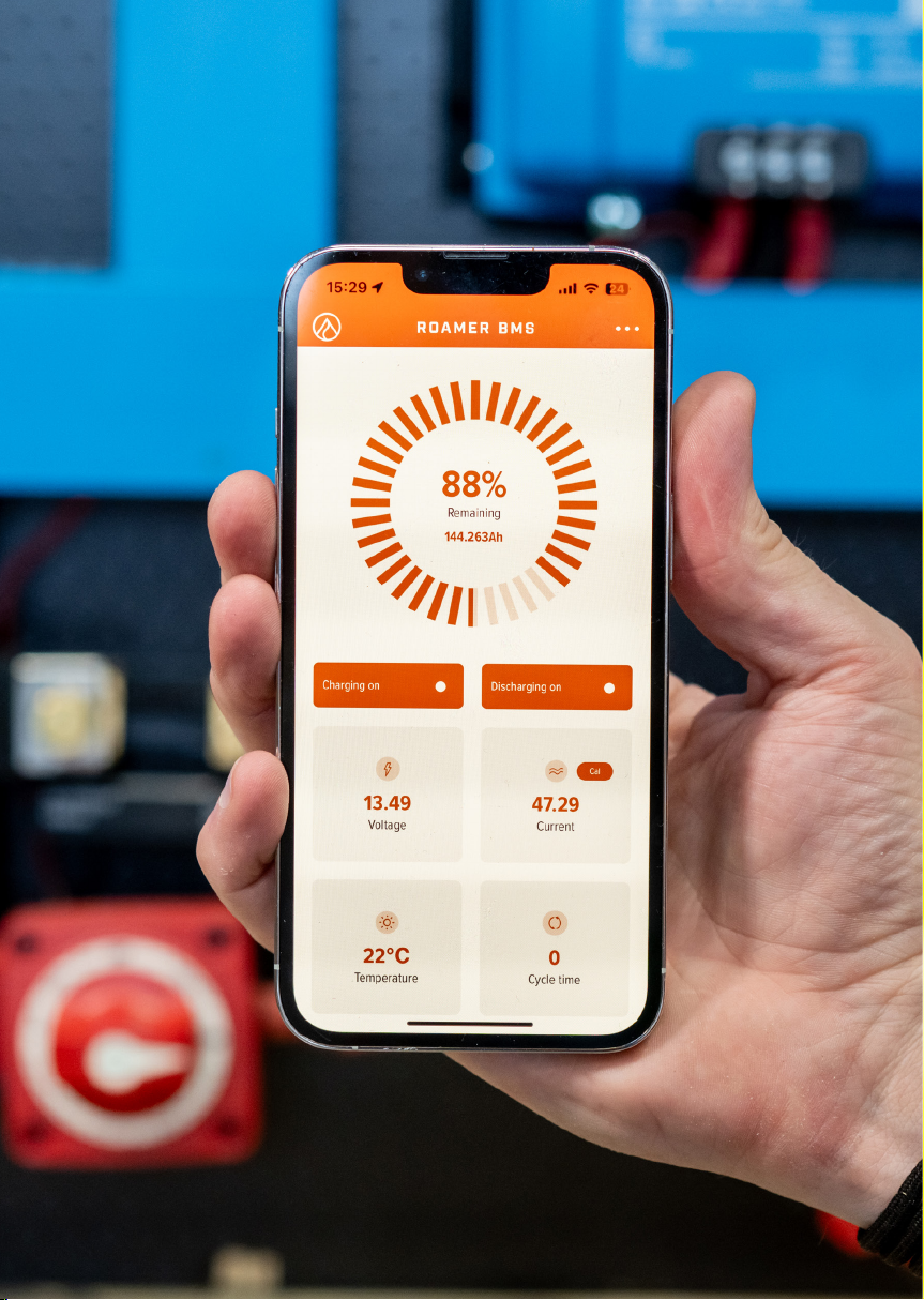
BMS dashboard
The dashboard gives you the main overview of your battery. The top ‘clock’ display
shows you the estimated state of charge and amp-hours remaining. Please note that
this state of charge reading is just an estimate, if it has not been calibrated recently
then this could be incorrect. See Troubleshooting for more tips on calibration.
Underneath this is the charging and discharging panel. This shows whether charging
and discharging are enabled or disabled. If there is an issue and BMS is in protection
mode, then one or both will be greyed out. It is also possible to manually turn o
charging and discharging but we do not recommend doing this during normal use.
The bottom panel shows:
Battery Voltage
This displays the total battery pack voltage as measured across the cell pack.
Battery Current
This displays the sum of any current flowing in and out of your battery.
Cell Temperature
This displays the average internal temperature of the battery, measured from multiple
points within the cell pack.
Cycle Count
This shows the estimated number of cycles (full discharge and full charge) that the
battery has completed.

18
BMS details page
The detailed information page provides further data about your battery.
The cell voltage section shows the voltage of each cell in your battery. Under normal
operation the cells voltages should be similar (within 0.1V). The only exception is
when the battery is at 100% state of charge. If you notice that there is a significant
dierence between cells at any other time, please contact Roamer as this may
indicate a problem with your battery.
Clicking the Protect State button in the top right-hand corner of the details page takes
you to the Protect State page. If your battery is in protection mode for any reason, this
is where you will find the error code. Under normal operation, no protection states
should be highlighted.
The following list provides details of the protection state codes:
Charging Status and Alarms Discharging Status and Alarms
SOCC = Over Current Charge (charging current too high)
SOCD = Over Current Discharge (discharging current too high)
OTC = Over Temperature Charge (its too hot to safely allow charging)
OTD = Over Temperature Discharge (it’s too hot to safely allow discharging)
UTC = Under Temperature Charge (too cold to safely allow charging)
UTD = Under Temperature Discharge (too cold to safely allow discharging)
COV = Cell Overvoltage (Individual cell voltage is too high)
CUV = Cell Undervoltage (Individual cell voltage is too low)
FC = Fully Charged (Overall battery voltage is too high)
FD = Fully Discharged (Overall battery voltage is too low)
ASCD = Automatic Short Circuit Detection (Surge current detected)
CHG = Charging Allowed (this is the default when everything is OK)
DSG = Discharging Allowed (this is the default when everything is OK)

19
Troubleshooting
Q) I cannot connect to my battery via Bluetooth.
A) Check that your phone is within range of the battery (approximately 5m). If in
doubt, place the phone on the lid of the battery for maximum signal strength. Check
that your phone/tablet’s Bluetooth is enabled, and you have allowed all permissions
requested by the Roamer BMS App. On Android phones this includes GPS. Click
“scan” at least twice and if that still does not work, force close the app on your phone
and reopen it. Check that another phone/tablet is not connected to the battery as this
blocks any new connections. Place your battery on charge, a completely flat battery
may not be able to connect correctly.
Q) My battery will not charge/discharge.
A) There are a few reasons this could be, the first step is to determine if this is an
internal battery issue or an external cabling/equipment issue. You can verify this on
the Roamer BMS app home page, look to see if either charging or discharging button
is turned o (button will be greyed out if o – this means it is in protection mode). If it
is in protection mode, then check the protect state page for the corresponding error
code. If all is functioning normally, the only buttons to be highlighted orange would
be CHG (charging allowed) and DSG (discharging allowed). Please see app section of
the manual for error code descriptions.
Q) My App is reporting incorrect amp-hours (Ah) remaining or
percentage (%).
A) The Roamer BMS App estimates the remaining percentage based on the current
flowing in and out of your battery. On the first charge of the battery this Ah remaining
value may be out of calibration and show a figure that is much higher than should
be possible for the battery capacity. The battery will therefore require a full cycle
including discharging down to the Pack Low Voltage threshold (10.8V for a 12V
battery, 21.6V for a 24V battery), this will reset the app to 0% and 0.0Ah remaining
and it should count accurately after this. Please note that the app reading for the
battery state of charge has no eect on the operation of the battery, BMS protections
for over charging and over-discharging are based on voltages only. Even if your app
is out of calibration and incorrectly reporting the state of charge, the battery will still
operate normally and all protections will remain in place.

20
Q) My battery is entering ASCD protection state when I connect my
inverter.
A) Inverters have large capacitors to smooth the current flow in and out of the
equipment, on first connection this can cause a surge current from the battery of up
to 4000A. When this happens, the BMS will go into protection state with a protect
code of ASCD (Automatic Short Circuit Detection) and both charge and discharge will
be switched o. The solution is to isolate the battery using the main battery switch
(or remove cables) and wait for protection state to reset. You can then pre-charge the
inverter and reconnect the inverter. Please see ‘discharging’ section of the manual for
tips on pre-charging.
Q) I can’t access the parameters page.
A) The parameters page contains important settings that control your battery’s
operation. We do not allow access to this by default as it is possible to cause damage
to your battery if parameters are set incorrectly. Accessing the parameters menu
without Roamer’s permission will invalidate your battery’s warranty. The password will
be provided through a support ticket if there is a need to change your parameters to
resolve an issue.
Q) I cannot resolve my issue.
A) Please get in contact with the Roamer Support Team on support@roamer.com
and we will be more than happy to assist. Please provide your battery model, serial
number, and order number along with a detailed description of your system and the
nature of the fault. Where possible, please also provide screenshots of the home
page of your Roamer BMS App, full details page, and the protection state page.
This manual suits for next models
3
Table of contents
Other ROAMER Batteries Pack manuals


