ROAMER HOME User manual

1
Document version number: 1.0
Document release date: 27/09/2023
www.roamer.com
ROAMER
USER MANUAL
Roamer HOME
LiFePO4 Leisure Battery

Roamer Batteries
Since founding Roamer in 2020, we have strived to create and
deliver exceptional products and service that give you the confidence
to venture further and live without limits. The company has grown
exponentially in the last three years, but our values and quality-first
approach are still as strong as they were on day one.
We’re committed to supporting o-grid lifestyles through the quality
manufacturing of superior LiFePO4 batteries, customer care and expert
support. We are confident that you’ll be delighted with the quality and
performance of your new Roamer battery but if you have any concerns
or questions, please get in touch straight away.
Steve, Kate and the Roamer team
Roamer Batteries
Powering your O Grid Adventures
www.roamer.com

Safety
Roamer have taken every precaution to ensure that our batteries are
as safe as possible and give you complete peace of mind while using
our products. No battery is 100% safe however, and caution should
always be taken when handling or operating equipment containing, or
connected to, high-capacity energy storage devices.
LiFePO4 batteries should only be installed and operated by a
competent person. Please read this manual carefully and pay particular
attention to the recommended charge, discharge, and temperature
limits as these may be dierent to the Battery Management System
(BMS) maximum limits.
Please read the separate Safety User Guide carefully. This contains
essential safety information and best practice on how to use your
battery. If you have any concerns or questions about safety, please do
not hesitate to contact Roamer at support@roamer.com

Contents
What else is in the box?
What’s inside a Roamer battery?
Battery layout
Before you start
Installation
Connecting power cables
Parallel connection
Connecting RS485 link cables
Configuring DIP switches
Connecting your battery to a PC
Connecting your battery to an inverter
Discharging
Charging
Low temperature charging
Monitoring state of charge
Storing your battery
Troubleshooting
Tech specs
Warranty
Returns & refund policy
Contact Roamer
5
5
7
7
8
9
9
10
10
11
11
13
14
15
16
17
19
20
21
23
24

5
What else is in the box?
• User manual
• Safety information sheet
• Warranty terms and conditions
• 2x M8x16mm stainless steel terminal bolts with captive washers
• 2x M8x10mm stainless steel terminal bolts with captive washers
• Cable pack (inc. programming cable and battery link cable)
Please retain all documentation for future reference, but if you misplace them or
decide to recycle them then digital versions are also available on our website. If any
of these parts are missing, please contact us at support@roamer.com or call
our technical support team on (+44) 113 8878335 to arrange a replacement.
What’s inside a Roamer battery?
The Roamer HOME battery consists of sixteen 105Ah 3.2V grade A LiFePO4 cells
connected in series to create a pack with nominal voltage of 51.2V and charge
capacity of 105Ah. This provides a total energy capacity of 5.38kWh. Cells oer
an industry leading 4000 cycles @ 80% depth of discharge and are rated for a
continuous charge and discharge of 1C (105A).
Each battery includes a premium Battery Management System (BMS) which protects
the battery cells from low voltage (over-discharge), high voltage (over charge), over-
current, short-circuit, and under or over temperature. Charging and discharging are
controlled separately, allowing you to discharge even when charge protection is in
place. The BMS can connect to other devices via CAN protocol via one of the RJ45
ports on the front panel. This enables connection to a wide range of inverters for BMS
managed charging, as well as CAN battery monitoring systems. For specific inverter
protocols and set up instructions, please see the separate setup guides on our
website, or contact Roamer Support.
Your battery is professionally constructed using precision engineered steel brackets,
CNC-cut epoxy insulation board and high-capacity busbars and cable. We take
immense pride in the quality and reliability of our batteries, but we also make them
fully serviceable in case of problems or if an upgrade becomes available. While the
case can be opened for repairs and upgrades, please do not try to do this yourself
without speaking to Roamer Technical Support as you will invalidate your warranty.

7
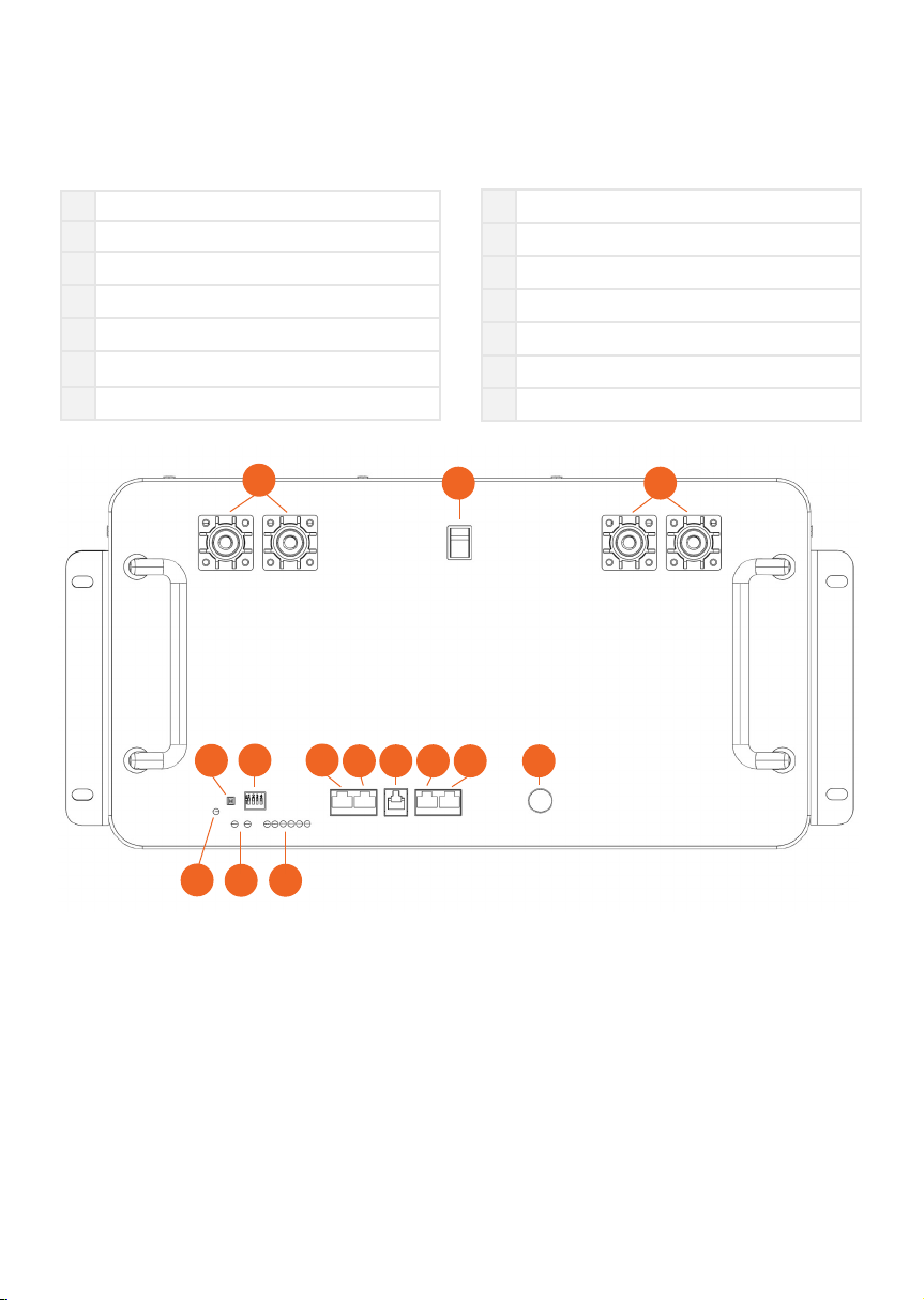
Battery Layout
Please refer to the guide below for connection identification and use information.
1Positive Battery Terminals
2Power Switch
3Negative Battery Terminals
4Reset Switch
5Address DIP Switches
6RS485 RJ45 Socket A
7BMS-CAN RJ45 Socket
8RS232 RJ11 Socket
9RS485 RJ45 Socket B1
10 RS485 RJ45 Socket B2
11 WiFi & Bluetooth Antenna
12 Power On
13 Status LEDs
14 Charge State LEDs
12 3
1413
12
57
68 9 10 11
4
Before you start
Prior to installation please check that all accessories and hardware is present, and
that the battery has not been damaged during transit. Check that the battery is
operating normally by switching it on using the main rocker switch on the front panel
while you press and hold the RESET button on the front panel for 3 seconds to boot.
During the boot process, the six capacity indicators (4), alarm indicator (5) and output
indicator (6) on the front panel should all turn on. The alarm indicator should turns o
while the output indicator remains on. The capacity indicators will settle to show a bar
that estimates the remaining charge in the battery.

8
If the ALM alarm indicator flashes after the battery is turned on, it means that the
battery is in an alarm state. If the alarm LED shows on first power on, press and hold
the reset button for 10 seconds until all the LEDs are turned on, then release the reset
button. This resets the battery allow the battery to reset and confirm whether the
alarm is cleared. If the alarm LED persists after the battery as rebooted, it is likely to
be a battery undervoltage flag (usually caused by the battery being left without a float
charge for a long period). In this case, place the battery on charge for 30 minutes to
raise the pack voltage. If the alarm is cleared, the battery can be used normally. If the
alarm persists, please contact Roamer customer support for further guidance.
Installation
Your battery should be installed lying flat with the Roamer logo the correct way up,
or upright with the Roamer logo facing upwards. If the battery is installed in a vehicle,
then it is crucial that the battery is securely fastened down so that it cannot slide
while the vehicle is moving. It must also be accessible so it can be disconnected and
removed in an emergency. We recommend always having tools available including
cable cutters and a socket wrench of the correct size.
You should install the battery in a way that avoids exposing it to extreme heat or cold,
and facilitates an even temperature distribution across the whole battery pack.
The Roamer HOME battery should be installed in accordance with one of the
methods outlined below:
Standard cabinet (rack) installation: Install the battery pack and fix it with suitable
bolts or fixings (not supplied) in the front and rear mounting brackets. The Roamer
HOME has a size of 5U.
Vertical mounting: The battery can be sat on its end with the terminals pointing
vertically upwards. The battery should be secured using the front and rear brackets
were possible to prevent movement or the battery falling over. Alternatively, place
bracing around the battery to ensure it cannot move.
If you intend to use an alternative mounting method, please contact Roamer customer
support for guidance.

9
Connecting power cables
Please ensure the battery is switched o before connecting cables.
Your battery comes supplied with M8 bolts with flat washers and spring washers pre-
attached. You should terminate your battery cables with copper tube ring terminals
with an 8mm hole. The cable termination should be placed flat, directly in contact
with the battery terminal. The bolts should be tightened to a torque of 10Nm.
You should only have one main cable connected to each battery terminal bolt. There
are two positive and two negative terminals on each battery to facilitate connection
between multiple batteries in parallel. Both positive (or negative) terminals are
directly connected internally so you can choose which is the primary and which is the
secondary terminal.
Parallel connection
Multiple batteries can be wired together in parallel to create higher capacity battery
banks.
Parallel configuration is achieved by connecting the positive terminals of multiple
batteries together to create one common positive node and connecting the negative
terminals together to create one common negative node. The capacities and
maximum current outputs are added together but the voltages are not. For example,
two 48-105HOME batteries in parallel will have a total capacity of 210Ah, a peak
delivery current of 200A, and a nominal system voltage of 51.2V.
• It is possible to connect to 15 HOME batteries in parallel.
• We do not recommend connecting HOME batteries in series.
• All batteries must be fully charged and allowed to settle to within 0.05V of each
other before connecting in parallel.
• Batteries in parallel series must be the same brand, voltage, capacity, and age.
• If connecting two batteries in parallel, you should take the positive cable to loads/
chargers from battery A and the negative cable from loads/chargers to battery B.
• If connecting more than two batteries in parallel, you should connect each battery
to a busbar rather than connecting directly.

10
Connecting RS485 link cables
When using multiple batteries in parallel, you should use the link cables provided (or
any other standard RJ45 ethernet cable). You should use the two ports on the right
side of the battery as you look at it, labelled as RS485 / Link in the diagram. Connect
one end of the link cable to one RJ45 socket on the first battery, and the opposite
end of the link cable to the corresponding RJ45 socket on the next battery. Repeat
this process by alternating pairs of RJ45 sockets until all batteries have been linked.
Configuring DIP switches
When multiple batteries are connected together, you need to allocate each battery a
unique address so that any connected devices and monitoring equipment are able
to identify each one separately (by default they will all be set to address 0). Do this
by changing the DIP switches (the little red and white selector switches) on the front
panel. These use binary encoding, so up to 16 unique addresses can be set using just
four switches. You should set the address of the first battery as ‘1’ and then increase
incrementally as per the diagram below.
0 1 2 3
4 5 6 7
8 9 10 11
12 13 14 15

11
Connecting your battery to a PC
Roamer provide windows PC utility software to monitor the status of your battery
and configure system parameters. First, you’ll need to connect the provided USB
to RS485 adapter to the 9-pin D-SUB to RJ45 cable. They should mate together
easily using the captive screws to make a secure connection. The resulting cable
should now eectively be USB to RJ45. When connecting to a PC, you should use
the far left RS485 port, as shown in the connection diagram. The PC software can be
downloaded from roamer.com along with a detailed programming guide.
Connecting your battery to an inverter
There are two methods of controlling charging via a solar inverter or solar charger.
The first is to set it up like you would with a lead acid battery, where there is no
direct communication between the inverter and battery. Charging and discharging
are controlled using a voltage and current-based system and a 3-stage charge
profile. When using this method, it is important to configure charge voltages as per
the recommended settings given later in the manual. Charging will therefore be
controlled via the inverter/charger, it will charge up to the preset voltage and then
stop. If there are any issues, the battery BMS will protect the battery by preventing
charging or discharging as required. Alarm signals can be communicated to a smart
controller, such as a Victron Cerbo, via CAN; or to a PC using RS232 or RS484 serial.
The second way is to switch to battery-controlled charging, where the BMS takes
control the inverter or charger’s charging and discharging parameters. This has
advantages and disadvantages, and it may not suit all applications. The main benefit
of this method is to provide expanded battery data and alarm flags to the inverter
and monitoring system. When using this method, you should ALWAYS configure the
default charge settings on the inverter or charger to match the recommended voltage
settings for the battery. This ensures that in the event of a communication failure the
battery will not be over charged or over discharged.
Roamer HOME batteries can communicate with almost any CAN enabled inverter,
although some may require a firmware update on the inverter. It may also be
necessary to make a custom RJ45 cable with an alternative pinout depending on
the specific hardware. Please check the Roamer website for inverter specific set-up
guides. If we do not have instructions for your inverter then please contact us and we
can provide further guidance.
12

13
Discharging
Your Roamer HOME battery can deliver extremely high continuous discharge currents
and allows the operation of high-power appliances either directly at DC 48V or at
mains AC voltages (230V in the UK and mainland Europe) via an inverter. You should
ensure that all connecting cables and the main battery cables are sized appropriately
for the expected current draw, and the correct size and type of protective fuse is
used. Please refer to the inverter manual for guidance.
The recommended maximum inverter size that can be used with multiple Roamer
HOME batteries are given in the table below. If you are installing multiple batteries
in parallel, you can connect a larger inverter. To allow for unbalanced loading on the
batteries, we recommend limiting the total discharge current to 80% of the total rating
from all batteries added together.
48-105HOME
BMS Max Discharge Current [A] 210 (continuous), 250 (<10s)
Battery Max Recommended Discharge Current [A] 105
Battery Max Recommended Inverter Power [VA] 5000
Number of Parallel 48-105HOME Batteries 1x 2x 3x 4x
Bank Max Recommend Discharge Current [A] 105 168 252 336
Max Recommended Inverter Power [VA] 5000 8000 12000 16000

14
Charging
You should choose a charger or inverter-charger with an appropriate default (or
configurable) LiFePO4 charge profile. The Roamer BMS will automatically prevent you
from overcharging the battery by blocking further charging when the high voltage
threshold is reached. This is an emergency protection however and should not be
relied upon as a substitute for an appropriate LiFePO4 charger.
The ideal charge profile for your battery includes a bulk charging phase at a constant
current up to the target absorption voltage of 56.8V, followed by an absorption phase
up to 1 hour. A float phase is not required.
Most multistage chargers have bulk, absorption and float stages that can be
configured via a Bluetooth app or selector switches. Some brands use dierent
terminology, but the purposes are the same. You should choose the profile that
most closely matches the parameters given below, with ideal and acceptable charge
voltages also shown:
• Bulk/Absorption/Boost/Target Voltage: 56.8V
• Float/Storage Voltage: 54V or O
• Absorption Time: 1 hour (0 to 2 hours is ok)
• Equalisation: O (or equal to boost voltage with equalisation time 0)
• Temperature Compensation: O
Note that when the battery is new, you may see Cell Overvoltage (COV) warnings
when the battery is almost at 100% state of charge. This is usually due to the cells
drifting slightly out of balance during extended periods of storage or transit. The
solution is to reduce charge voltage to 55.8V then continue to use the battery as
normal. After 20-30 cycles the cells will come back into balance, after which you can
then increase charge voltage back to 56.8V.

15
Low temperature charging
Standard LiFePO4 batteries should not be charged at temperatures below 0°C as
this can permanently damage the cells. Roamer batteries therefore include a low
temperature charge protection function in the BMS which will prevent you charging if
the internal battery temperature reaches below this point. This protection will remain
in place until the internal temperature rises back above 5°C. Due to the size and bulk
of the prismatic battery cells, it can take several hours for the internal temperature to
match the external ambient temperature, and for all cell temperatures to equalise.
We do not recommend applying an external source of direct heat to either the
cells or the battery casing as this can change the temperature of the sensors in the
battery, but not the temperatures within the cells themselves, leaving them at risk of
permanent damage. If you need to warm the battery, gently heat the air around the
battery and leave the battery to acclimatise for at least two hours.
To maintain a long and healthy life for your battery and to minimise safety risks, you
should also reduce charge currents according to the battery temperature. Please pay
attention to the recommended charge currents are given below, failure to adhere
to this advice could lead to premature battery failure and will increase the risk of a
battery fire.
48-105HOME
BMS max rated current [A] 210
Max recommended charge current at 25°C [A] 105
Max recommended charge current at 10°C [A] 50
Max recommended charge current at 5°C [A] 25

16
Monitoring state of charge
The state of charge (SoC) is tracked by the BMS by monitoring the current flowing
in and out of the battery, combined with additional information about self-discharge,
internal losses, and cell condition. This can be viewed through the PC software or
via a connected monitoring system. You could also install an external shunt-based
battery monitor. As a second point of reference the battery capacity can be roughly
estimated from the cell or pack voltage.
There are subtle dierences in the voltage profiles of dierent cells and batteries, so
the below parameters are for reference purposes only. The table below shows the
approximate SoC at dierent voltages for a single cell, and the full 48V 16S cell pack.
Except for the first line, all voltages are ‘resting’ voltages i.e., after the battery has
been sat without charging or discharging for 30 minutes.
Note how the voltage at 99% is very dierent to 100% but there is hardly any
dierence in voltage between 20% and 80%. Voltage is therefore more useful as a
guide when the battery is nearly full, or nearly empty. For example, you can consider
any resting voltage of 53.6V or above as being full. You can also consider anything
below 51.2V to be very low and if you see this as a resting voltage, you should aim to
recharge as soon as possible.
State of Charge at 25ºC Single Cell LiFePO4 [V] 48V LiFePO4 [V]
100% (Charging) 3.55 56.80
100% (Resting) 3.40 54.40
99% 3.35 53.60
90% 3.33 53.20
80% 3.31 52.88
70% 3.29 52.64
60% 3.28 52.40
50% 3.26 52.20
40% 3.25 52.00
30% 3.24 51.80
20% 3.20 51.20
10% 3.03 48.40
0% 2.50 40.00

17
Storing your battery
If you happen to need to store your battery for an extended period – for example
through the winter months – we have a few recommended tips to prolong the life of
your battery.
• Before putting into storage, you should discharge it to between 52.0V and 53.0V
(equivalent to 40% to 80% state of charge) and fully isolate the battery from any
chargers or loads.
• Never store your battery at 100% state of charge or continuously charge the battery
via solar or a trickle charger. This is one of the worst things you can do to a lithium
battery as it will degrade the LiFePO4 cells and reduce the life of your battery. If
you need to leave the battery connected and on charge, then set the charger to a
storage voltage of 52.8V.
• Keep it in a dry location with a stable temperature. While cold temperatures are
generally ok for storage, you should avoid very warm temperatures (above 40 °C).
• Your battery will self-discharge by approximately 3% every month so it is normal to
find it in a lower condition than you left it but do not let it drop too far.
• Cells will be damaged if you allow voltage to drop below 2.5V per cell. You should
check the battery app regularly and top up the charge if needed.
• Note that the BMS app will not record any self-discharge while in storage so you
should use voltage as a guide, not the percentage shown on the app. The State of
Charge calibration may also need to be reset when using the battery again after a
long period of storage.

18

19
Troubleshooting
LED indicators
• 1x green power on indicator
• 6x green capacity indicators
• 1x red warning indicator
Capacity indication
Status indication
State Charge Discharge
Capacity Indicator (SOC) L1 L2 L3 L4 L1 L2 L3 L4
0-25% OFF OFF OFF BLINK OFF OFF OFF ON
25-50% OFF OFF BLINK ON OFF OFF ON ON
50-75% OFF ON ON ON OFF ON ON ON
75-100% BLINK ON ON ON ON ON ON ON
Run Indicator ON BLINK
System
status
Event RUN LED ALARM
LED
SOC LED
R1 A1 L1 L2 L3 L4
Shutdown OFF OFF OFF OFF
Standby Normal BLINK1 OFF OFF
Alert BLINK1 BLINK2 OFF
Protect ON OFF BLINK 2 ACCORDING TO SOC
Normal ON OFF BLINK 2 ACCORDING TO SOC
Overvoltage Alarm ON OFF BLINK 2 ACCORDING TO SOC
Charge Overcurrent Temperature Alarm ON BLINK 2 BLINK 2 ACCORDING TO SOC
Overvoltage Protection BLINK 1 OFF ON
Overcurrent Protection ON OFF BLINK 2 ACCORDING TO SOC
Discharge Normal BLINK 3 OFF BLINK 1 ACCORDING TO SOC
Alert BLINK 3 BLINK 2 BLINK 1 ACCORDING TO SOC
Undervoltage Protection BLINK 1 BLINK 2 BLINK 1 ACCORDING TO SOC
Overcurrent/Short-circuit/Reverse OFF ON OFF
Blink 1 = 0.25S On 3.75S O
Blink 2 = 0.5S On 0.5S O
Blink 3 = 0.5S On 1.5S O
You can view fault codes via the PC software.
If you have a persistent alarm signal showing and are
unable to resolve it yourself, please contact Roamer
customer support.

20
48-105HOME2
Battery Specification
Nominal Voltage [V] 51.2
Current Capacity [Ah] 105
Energy Capacity [Wh] 5376
Cell Chemistry Lithium Iron Phosphate / LFP / LiFePO4 Prismatic Cells
Physical Specification
Length [mm] 435
Width [mm] 370
Depth [mm] 230
Weight [kg] 45
Electrical Specification
Min/Max Safe Voltage [V] 40.0/58.4
Recommended Absorption Charge [V] 56.8
Recommended Float Charge [V] 54.0
Max BMS Discharge Current [A] 210
Max Recommended Discharge [A] 100
Max Recommended Inverter Power [VA] 5000
Max. BMS Charge Current [A] 100
Recommended Max Charge Current >25°C [A] 50
Recommended Max Charge Current >10°C [A] 20
Recommended Max Charge Current >5°C [A] 10
Max Charge Current <0°C [A] 0
Operating Specification
Storage Temperature [°C] -20 to 40 (10 – 35 recommended)
Charging Temperature [°C] 0 to 60
Discharge Temperature [°C] -20 to 60
Average Cycle Life
6500 cycles @ 50% Depth of Discharge (25°C)
3500 cycles @ 80% Depth of Discharge (25°C)
2000 cycles @ 100% Depth of Discharge (25°C)
Tech Specs
Each table contains detailed technical parameters for our batteries
including charging information, operating conditions and more.
Do not use the battery outside of the recommended ranges.
This manual suits for next models
1
Table of contents
Other ROAMER Batteries Pack manuals


