Robern VESPER EDGELINE LIGHTS User manual

Part no. 209-1330 01/06/21
Vesper Edgeline Lights
1
© 2020 Robern, Inc. 701 N. Wilson Ave. Bristol, PA 19007 U.S.A.
800.877.2376 www.robern.com
TOOLS NEEDED / PARTS - 3
ASSEMBLING THE BRACKETS - 5
MOUNTING THE BRACKETS TO THE CABINET - 6
MOUNTING THE BRACKETS BETWEEN CABINETS - 7
ACCESS THE ELECTRICAL ENCLOSURE - 8
RECESSED INSTALLATION - 9
SURFACE INSTALLATION - 11
FINAL ASSEMBLY - 14
PRODUCT ALIGNMENT - 16
This instruction sheet contains information on how to install the Vesper Edgeline Lights. This series comes in many variations. Please
refer to the box or product label for the specic model number. A key is provided on page 2.
Save these instructions for future use and reference. An improper installation voids the warranty. Carefully inspect the lights for
damage. Installed products cannot be returned.
If you experience any problems with your lights, contact your dealer or Robern directly.
Limited Warranty — One Year Term
VESPER™EDGELINE LIGHTS
Installation Instructions
Important safety instructions - Save these instructions
Suitable for damp locations
CONTENTS
GENERAL INFORMATION
Part no. 209-1330 01/06/21
Vesper Edgeline Lights
2
© 2020 Robern, Inc. 701 N. Wilson Ave. Bristol, PA 19007 U.S.A.
800.877.2376 www.robern.com
For dimmable models Robern recommends the Maestro® C•L® Dimmer from LUTRON®, Model # MACL-153M.
http://www.lutron.com/TechnicalDocumentLibrary/369613a.pdf
Other LED control dimmers may operate with this product but have not been tested or veried. It's recommended that the dimmer be
within reach of your mirror so you can adjust the brightness.
For on/off (non-dimming) operation a standard wall switch may be substituted in place of the dimmer.
DIMMER RECOMMENDATIONS
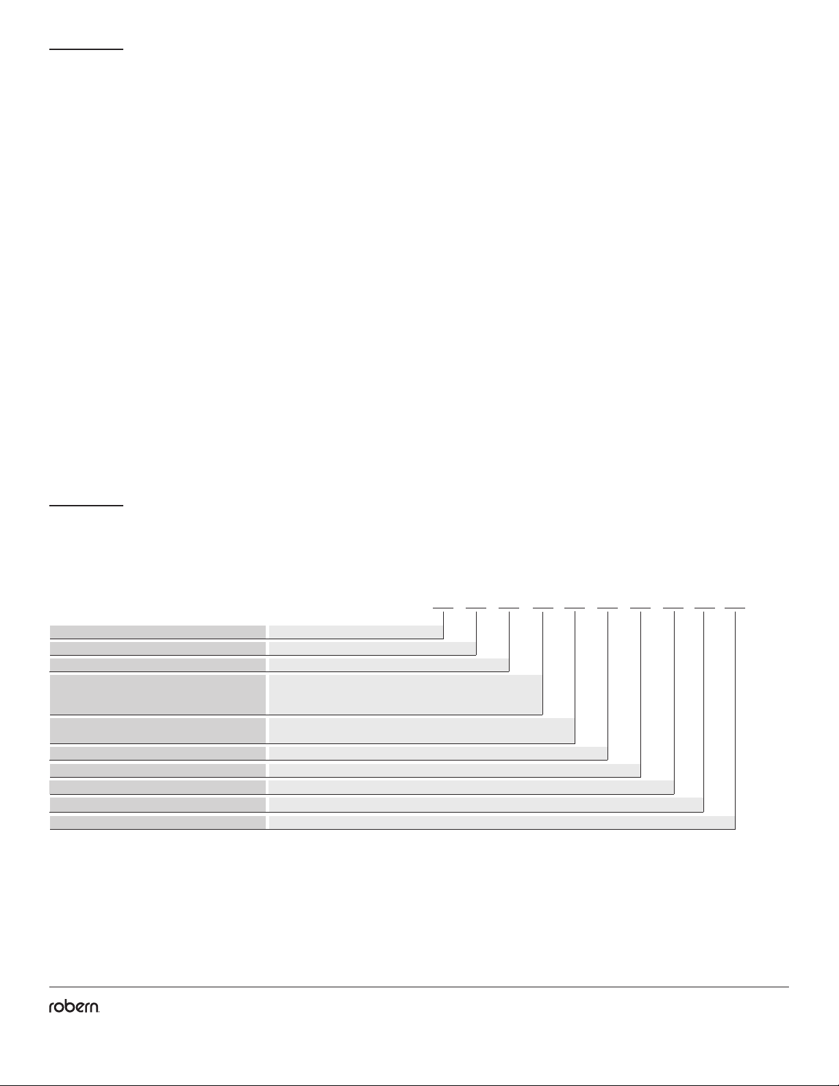
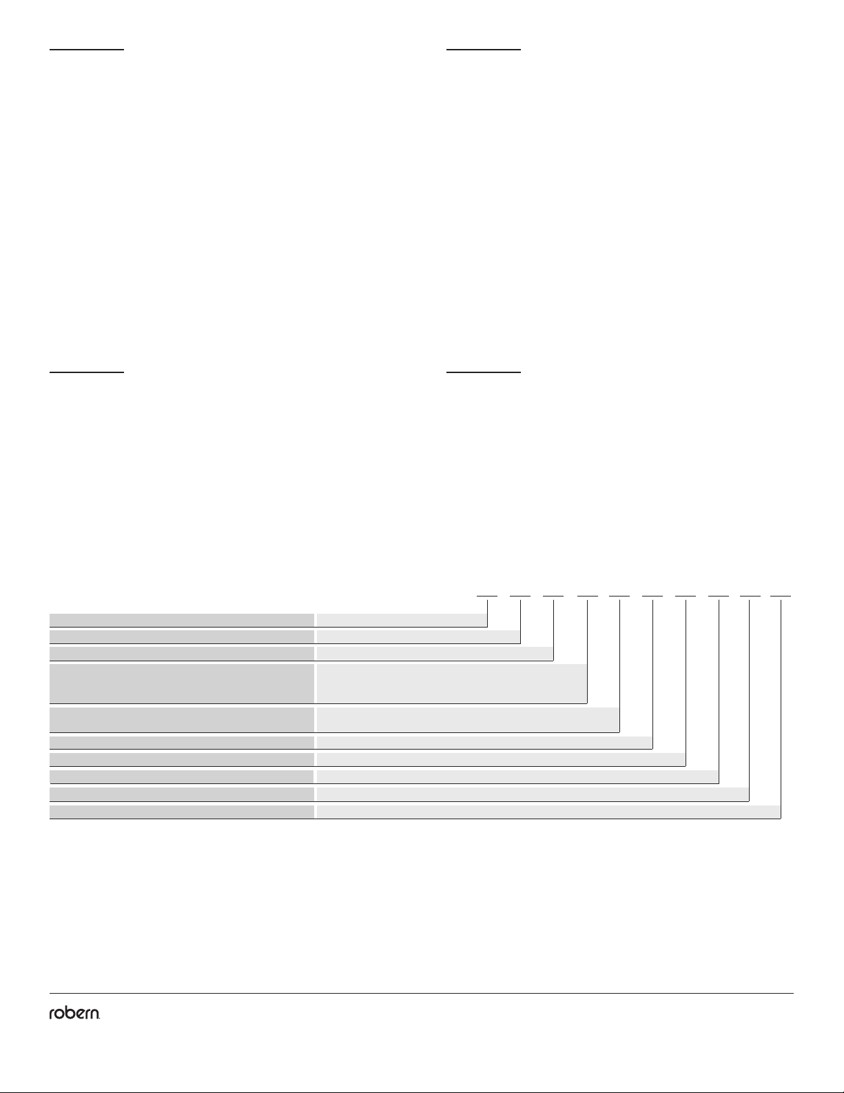
Model Numbers G L A 40 E L P S 3D
Product Line G = Vesper
L = Lights
A = 1-3/8" / 35 mm
30 = 30" / 762 mm
36 = 36" / 914 mm
40 = 39-3/8" / 1000 mm
E = Edgeline
L = LED
3 = 3000K
P = Pair Lamp
D = Dimmable
S = Silver
Light Name
Width
Quantity of Lamps
Engine Type
Category
Type of Lamp
Color Temperature
Height
Main Body Color
Use the chart below to learn how to read your light model number. This chart references the model number for 1-3/8" W x 40" H Vesper
Edgeline Lights with a silver metal nish. Consult the Robern Price Book for a complete list of model numbers.
MODEL NUMBERS
Part no. 209-1330 01/06/21
Vesper Edgeline Lights
3
© 2020 Robern, Inc. 701 N. Wilson Ave. Bristol, PA 19007 U.S.A.
800.877.2376 www.robern.com
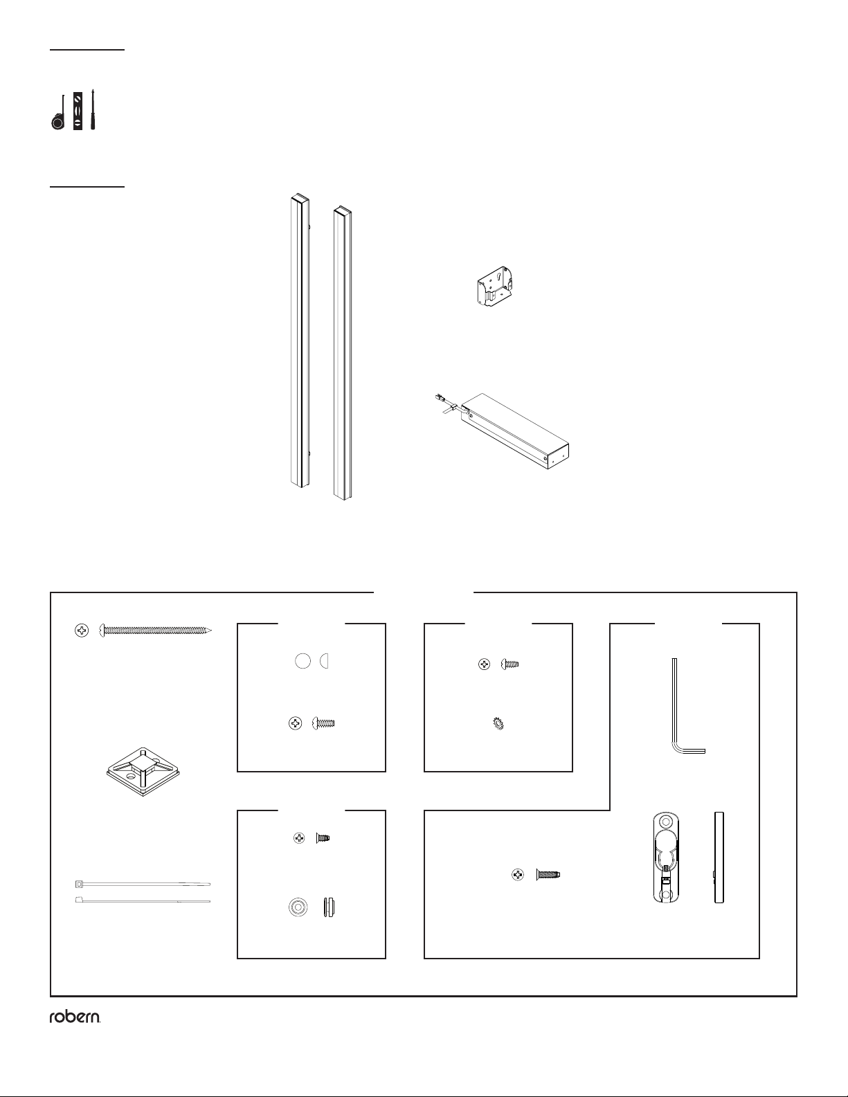
TOOLS NEEDED
[SS676]
(8) Screw, #10 x 1/2"
[SS344]
(3) Screw, #8 x 3/8"
[210-1661]
(4) Mounting Brackets
(2) Edgeline Lights
[205-3214]
(1) Electrical Enclosure
PARTS
Hardware Bag*
[216-1232]
[203-1068]
(3) #8 Lockwasher
* Depending on installation, not all parts will be used
[203-1057]
(1) 3/32" Allen Key
[219-1076]
(1) Cable Tie Holder
[203-1089]
(1) Cable Tie, 4"
[SS675]
(4) Screw, #10 x 3"
[205-3304]
(4) Adjustable
Button Receiver
[SS672]
(12) #10 Screw Cap
[203-1497]
(2) Screw, #8 x 3/8" Flat
[211-1351]
(2) Mounting Button
[203-1538]
(10) Screw, #8 x 5/8" Flat
Bag D*
[216-1230]
(2) Bag A*
[216-1227]
Bag B*
[216-1228]
(2) Bag C*
[216-1229]

Part no. 209-1330 01/06/21
Vesper Edgeline Lights
4
© 2020 Robern, Inc. 701 N. Wilson Ave. Bristol, PA 19007 U.S.A.
800.877.2376 www.robern.com
Unpack the Lights. Check the box thoroughly for all hardware and loose parts. Carefully inspect the xture for damage.
DANGER: Risk of personal injury. To avoid possible electrical shock, the electricity must be turned off at the circuit
breaker or fuse box before attempting any installation procedure.
DANGER: Risk of personal injury. To avoid possible electrical shock, the light xture must be properly grounded.
CAUTION: Grounding instructions for permanently connected products: This product must be connected to a grounded,
metal permanent wiring system or an equipment-grounding conductor must be run with the circuit conductors and connected to the
equipment-grounding terminal or lead on the product. All wiring should be done by a qualied licensed electrician.
IMPORTANT: Power for the lights should be provided separately from the electricity to the cabinet so that when lights are turned off,
cabinet electricity remains on.
NOTE: Requires minimum 120 VAC 15 amp circuit.
NOTE: Requires an approved compatible dimmer for installation (not included). Refer to the dimmer recommendation on page 2.
Observe all applicable electrical codes and building codes. Wire the light xtures in accordance with the electrical codes.
This xture is for indoor use only.
This installation may require the assistance of more than one person depending on your Light/Cabinet conguration.
NOTES
DANGER - RISK OF SHOCK -
DISCONNECT POWER BEFORE INSTALLATION

Part no. 209-1330 01/06/21
Vesper Edgeline Lights
5
© 2020 Robern, Inc. 701 N. Wilson Ave. Bristol, PA 19007 U.S.A.
800.877.2376 www.robern.com
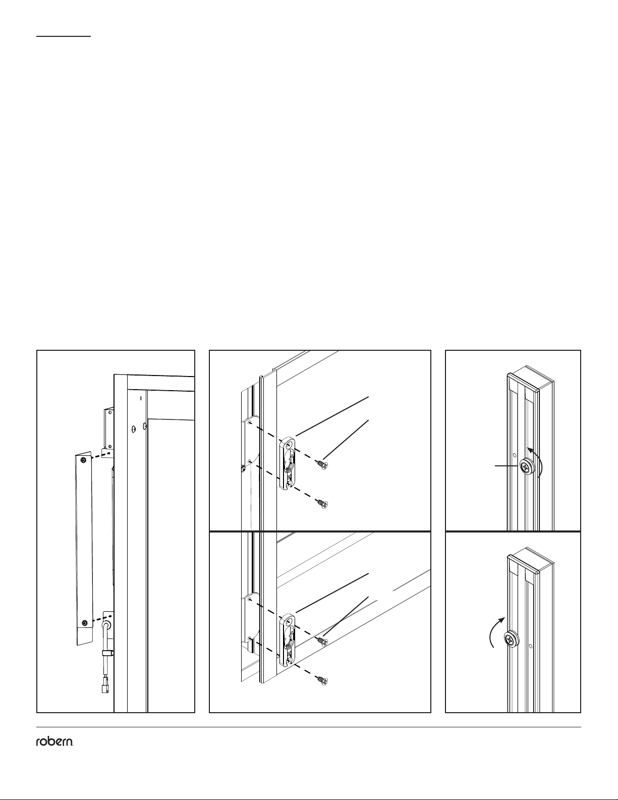
ASSEMBLING THE BRACKETS
Note: A RH (Right Hand) installation will require the electrical enclosure to be ipped, placing the exiting low voltage wire
closer to the upper bracket.
Note: For 1.375 pair installations involving more than one cabinet, a RH installation is required.
1. Orient one of the mounting brackets [210-1661] (as shown) ensuring that the electrical access screws on the electrical enclosure
[205-3214] are pointed toward the front of the cabinet.
2. Attach the included electrical enclosure [205-3214] to the bracket using the supplied #8 screws [SS344] and lockwashers [203-1068].
SS344 SS344
203-1068 203-1068
210-1661
205-3214
205-3214
Electrical
access screws
Low voltage
wire connection
Tabs always face
cabinet box
LH Installation RH Installation
Tabs always face
cabinet box
210-1661
Electrical
access screws
Electrical
access screws
Electrical
access screws
Low voltage wire
connection
Part no. 209-1330 01/06/21
Vesper Edgeline Lights
6
© 2020 Robern, Inc. 701 N. Wilson Ave. Bristol, PA 19007 U.S.A.
800.877.2376 www.robern.com
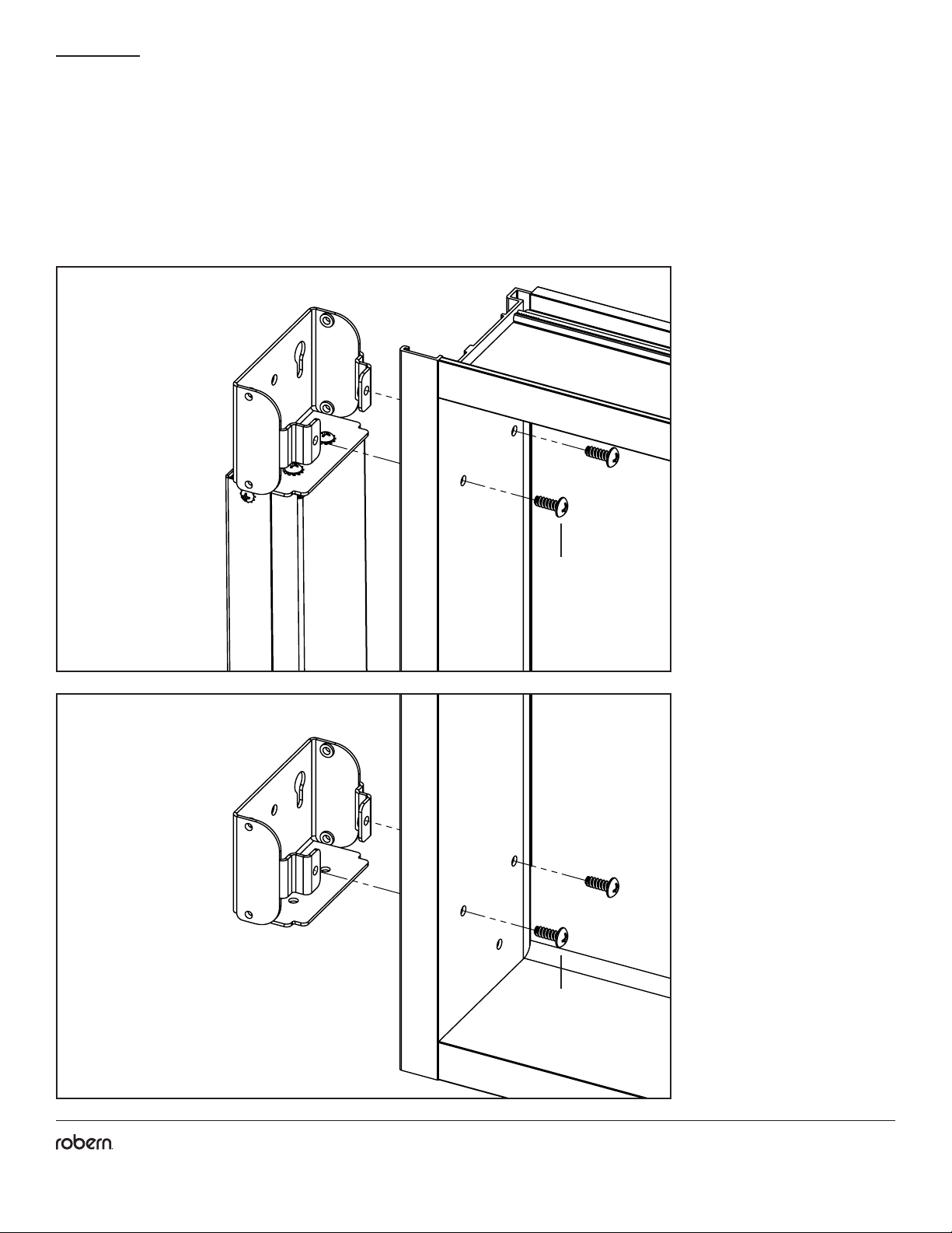
MOUNTING THE BRACKETS TO THE CABINET
Note: When mounting the lights between cabinets, see the following page.
1. Mount the brackets to the cabinet through the ganging locations, as shown, using the supplied #10 screws [SS676].
SS676
SS676
Part no. 209-1330 01/06/21
Vesper Edgeline Lights
7
© 2020 Robern, Inc. 701 N. Wilson Ave. Bristol, PA 19007 U.S.A.
800.877.2376 www.robern.com
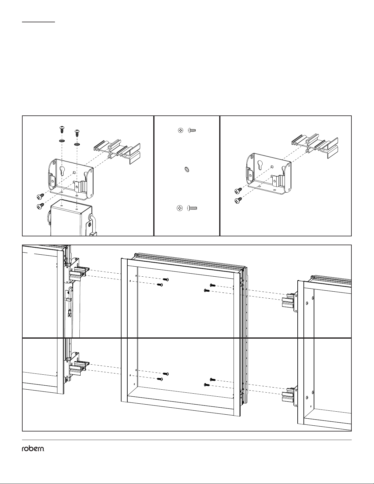
Note: A Ganging Kit (refer to the cabinet's instructions, sold separately) is required for the following instructions. All additional
components shown in the following steps will be included with the Ganging Kit. Enough components are included to gang two lights
between cabinets.
1. Using two #8 x 3/8" screws [SS344] and two lockwashers [203-1068], attach the mounting brackets to the Electrical Enclosure.
2. Using two #10 x 1/2" screws [SS676], attach each mounting bracket to a ganging block, included in the Ganging Kit.
3. Attach the mounting bracket assemblies to each cabinet with four #10 x 1/2" screws [SS676].
MOUNTING THE BRACKETS BETWEEN CABINETS
1 2
3
[203-1068]
(2) #8 Lockwasher
[SS344]
(2) Screw, #8 x 3/8"
[SS676]
(4) Screw, #10 x 1/2"
Part no. 209-1330 01/06/21
Vesper Edgeline Lights
8
© 2020 Robern, Inc. 701 N. Wilson Ave. Bristol, PA 19007 U.S.A.
800.877.2376 www.robern.com
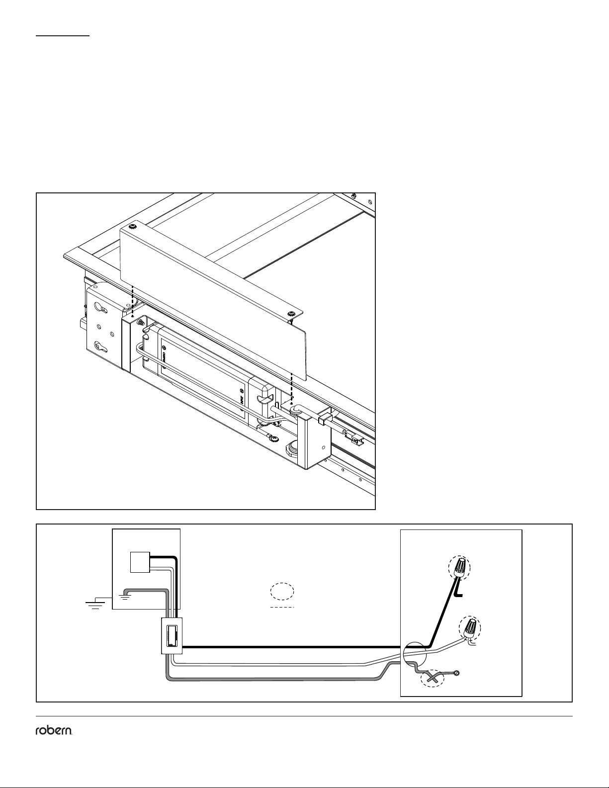
ACCESS THE ELECTRICAL ENCLOSURE
Lay the cabinet on a at level surface.
1. Remove the electrical enclosure cover to access the electrical wiring connections. Set the cover aside in a safe place.
* Make proper connections
according to the dimmer
manufacturer's instructions
CIRCUIT BREAKER
120VAC
15A
DIMMER*
FIELD CONNECTION
ELECTRICAL ENCLOSURE
LINE/BLACK
NEUTRAL/WHITE
GROUND
BLACK
WHITE
GROUND
1
Part no. 209-1330 01/06/21
Vesper Edgeline Lights
9
© 2020 Robern, Inc. 701 N. Wilson Ave. Bristol, PA 19007 U.S.A.
800.877.2376 www.robern.com
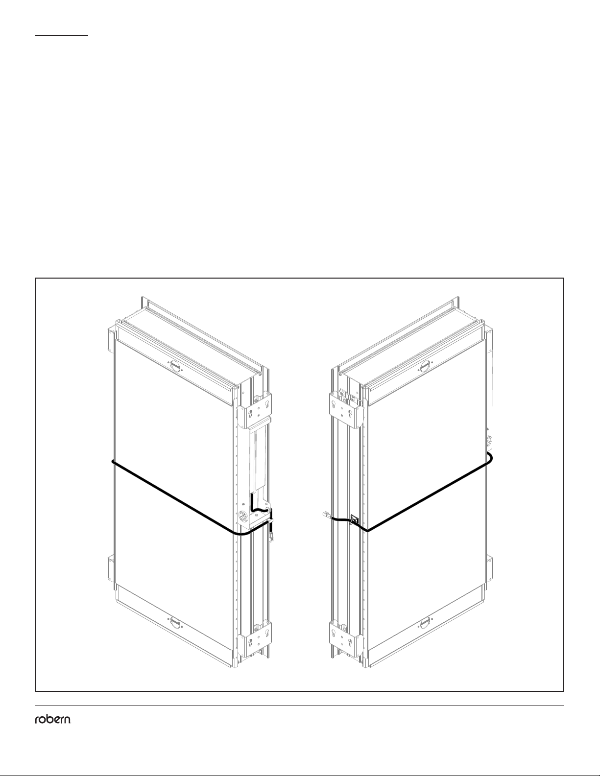
RECESSED INSTALLATION
When connecting the Electrical Enclosure to the remote light, it is recommended to route the wiring so that it does not get
pinched during recessed mounting.
1. Centered on the cabinet side opposite the electrical enclosure, attach the wire control mount [219-1076] to the cabinet side by
peeling and sticking it in place.
2. Route the wire around the back the cabinet until it reaches the wire control mount.
3. There will be an excess of length (wire will accomodate two ganged 24" cabinets). Coil the excess wire and secure in place with the
provided zip tie [203-1089].
Back View
Part no. 209-1330 01/06/21
Vesper Edgeline Lights
10
© 2020 Robern, Inc. 701 N. Wilson Ave. Bristol, PA 19007 U.S.A.
800.877.2376 www.robern.com
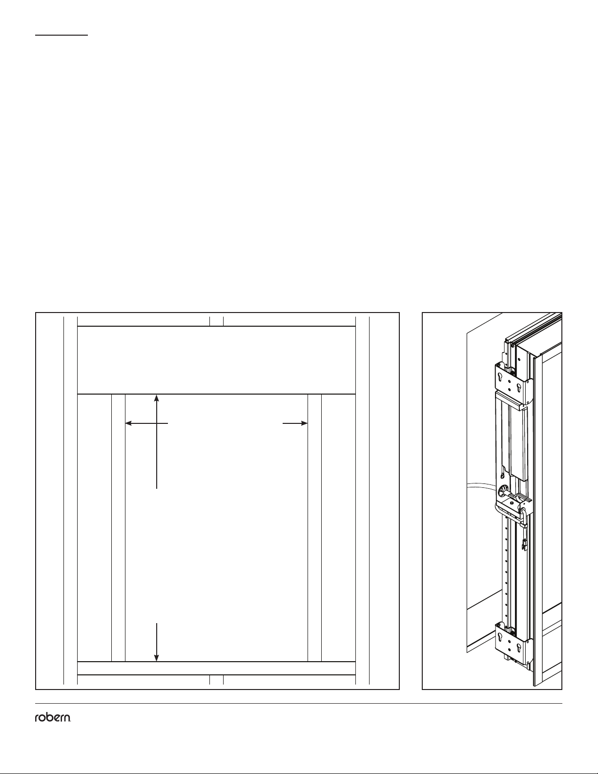
RECESSED INSTALLATION
4. With the electrical cover removed, support the cabinet on the edge of the recessed opening and feed the eld wire through the eld
wire strain relief at the back of each enclosure.
5. Push the cabinet assembly into the recessed opening until the back of the cabinet ange is tight to the nished wall surface.
6. Using a level, level and plumb the products in the opening. Shim as necessary. Using a square, make sure the cabinet is square in
all axis.
7. Make the electrical connection according to the electrical diagram on page 8.
Note: Refer to your cabinet's Instructions to insure there are no additional steps required prior to proceeding.
8. Mount the cabinet in place using the #10 Screws [SS674] provided with the cabinet.
RO Width =
Width of cabinet +
width of lights - 3/4" (19 mm)
RO Height =
Height of cabinet - 3/4" (19 mm)
Part no. 209-1330 01/06/21
Vesper Edgeline Lights
11
© 2020 Robern, Inc. 701 N. Wilson Ave. Bristol, PA 19007 U.S.A.
800.877.2376 www.robern.com
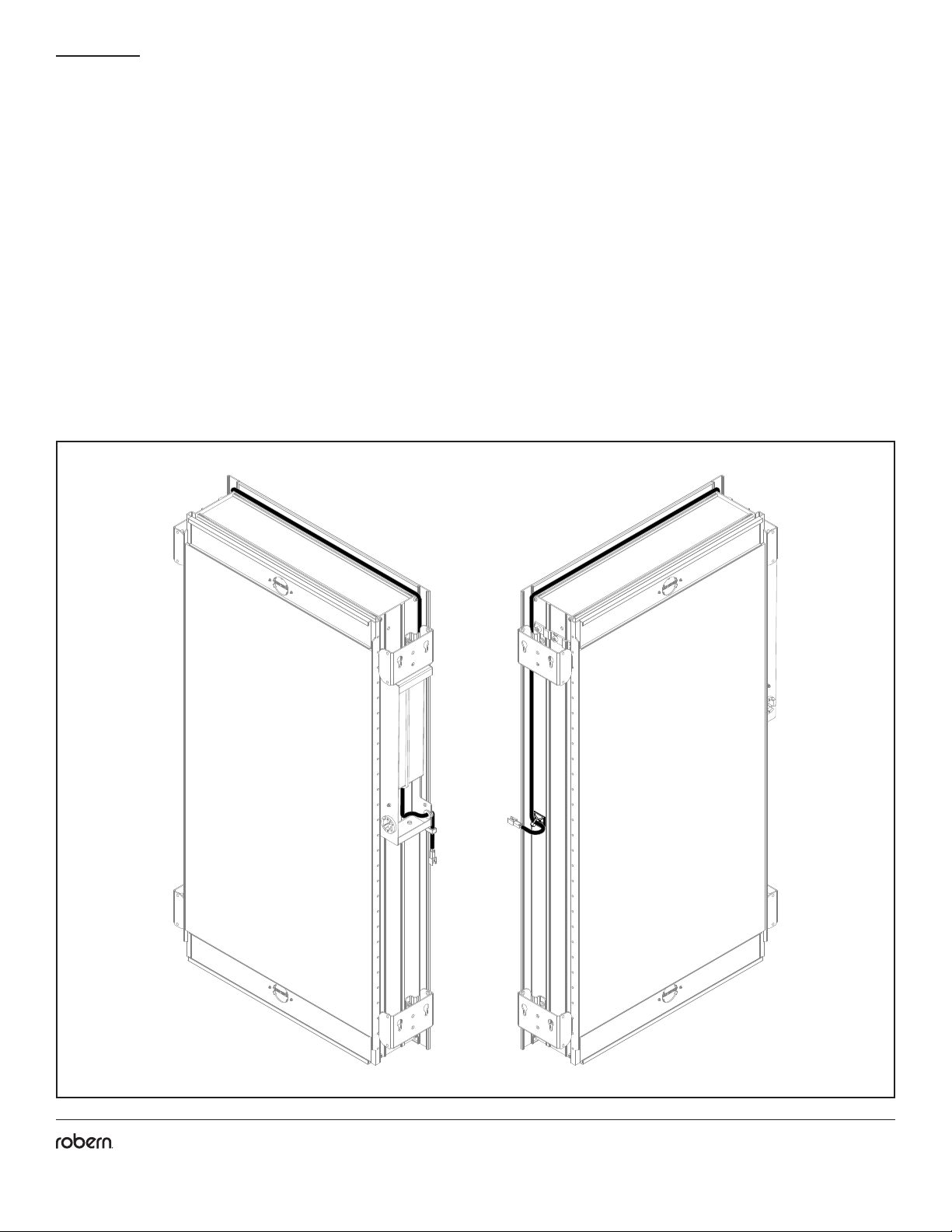
SURFACE INSTALLATION
Note: A Surface Mount Kit (refer to the cabinet's instructions, sold separately) is required for the following instructions. All additional
components shown in the following steps will be included with the Surface Mount Kit.
When connecting the Electrical Enclosure to the remote light, it is recommended to route the wiring so that it does not get
pinched during surface mounting.
1. Centered on the cabinet side opposite the electrical enclosure, attach the wire control mount [219-1076] to the cabinet side by
peeling and sticking it in place.
2. Route the wire upwards, between the cabinet box front ange and the brackets, and over the top of the cabinet until it reaches the
wire control mount on the other side of the cabinet box.
3. There will be an excess of length (wire will accomodate two ganged 24" cabinets). Coil the excess wire and secure in place with the
provided zip tie [203-1089].
Back View

Part no. 209-1330 01/06/21
Vesper Edgeline Lights
12
© 2020 Robern, Inc. 701 N. Wilson Ave. Bristol, PA 19007 U.S.A.
800.877.2376 www.robern.com
SURFACE INSTALLATION
4. With the electrical cover removed, feed the eld wire through the eld wire strain relief at the back of the electrical enclosure.
Note: Refer to your cabinet's Instructions to insure there are no additional assembly steps required prior to proceeding.
5. Mount the cabinet in place following the steps provided in the cabinet's instructions.
6. Make the electrical connection according to the electrical diagram on page 8.
C
LC
L
Cabinet Width + 1/2"
30 = 16-1/2" (419 mm)
36 = 22-1/2" (572 mm)
40 = 25-7/8 (657 mm)
Left Hand (LH) electrical
enclosure installation
eld wire stub out
30 = 24-3/4" (629 mm)
36 = 30-3/4" (781 mm)
40 = 34-1/8 (867 mm)
Right Hand (RH) electrical
enclosure installation
eld wire stub out

Part no. 209-1330 01/06/21
Vesper Edgeline Lights
13
© 2020 Robern, Inc. 701 N. Wilson Ave. Bristol, PA 19007 U.S.A.
800.877.2376 www.robern.com
SURFACE INSTALLATION
7. Drive the #10 Screws [SS676] provided with the Surface Mount Kit (sold separately) into the holes in the side kit brackets. Use a
penny (as detailed in gure 4 below) to set the depth distance.
8. Orienting the sidekit as shown below, insert the Screw Heads into the keyholes on the side of the upper and lower Light Brackets.
Note: If the bracket is not oriented correctly, the side kit cannot be lowered into place and may fall resulting in damage.
9. Slide the Sidekit down into place.
Note: If the Sidekit feels loose, move the sidekit back and forth to determine which screw feels loose. Lift and remove the sidekit from
the brackets and rotate the loose screw a 1/4 turn clockwise, repeating as necessary.
Note: If the Sidekit does not lower into place, remove the sidekit from the keyholes and rotate the screws a 1/4 turn counterclockwise.
8
SS676
1/16" (1.52 mm)
or the thickness
of a penny.
Front
toward
user
Rear
toward
wall
7
Part no. 209-1330 01/06/21
Vesper Edgeline Lights
14
© 2020 Robern, Inc. 701 N. Wilson Ave. Bristol, PA 19007 U.S.A.
800.877.2376 www.robern.com
1 2
FINAL ASSEMBLY
1. Close the electrical enclosure using the electrical enclosure cover, set aside in "Access the Electrical Enclosure".
Note: Leaving too much Field Wire in the enclosure could prevent it from closing properly and may cause damage to the internal
components.
2. Using the provided #8 screws [203-1538] attach an adjustable button receiver [211-1362] to each bracket. The screw head on the
button receiver must be facing down.
3. The orientation of the mirror and light can be adjusted by moving the button to the opposite hole. Remove the #6 Screw holding
the button in place by turning it counterclockwise (3A). Attach the Button to the second hole but inserting and turning the #6 Screw
clockwise (3B). Repeat these steps for the other button.
3A
3B
Button
[211-1351]
205-3304
203-1538
205-3304
203-1538
Part no. 209-1330 01/06/21
Vesper Edgeline Lights
15
© 2020 Robern, Inc. 701 N. Wilson Ave. Bristol, PA 19007 U.S.A.
800.877.2376 www.robern.com
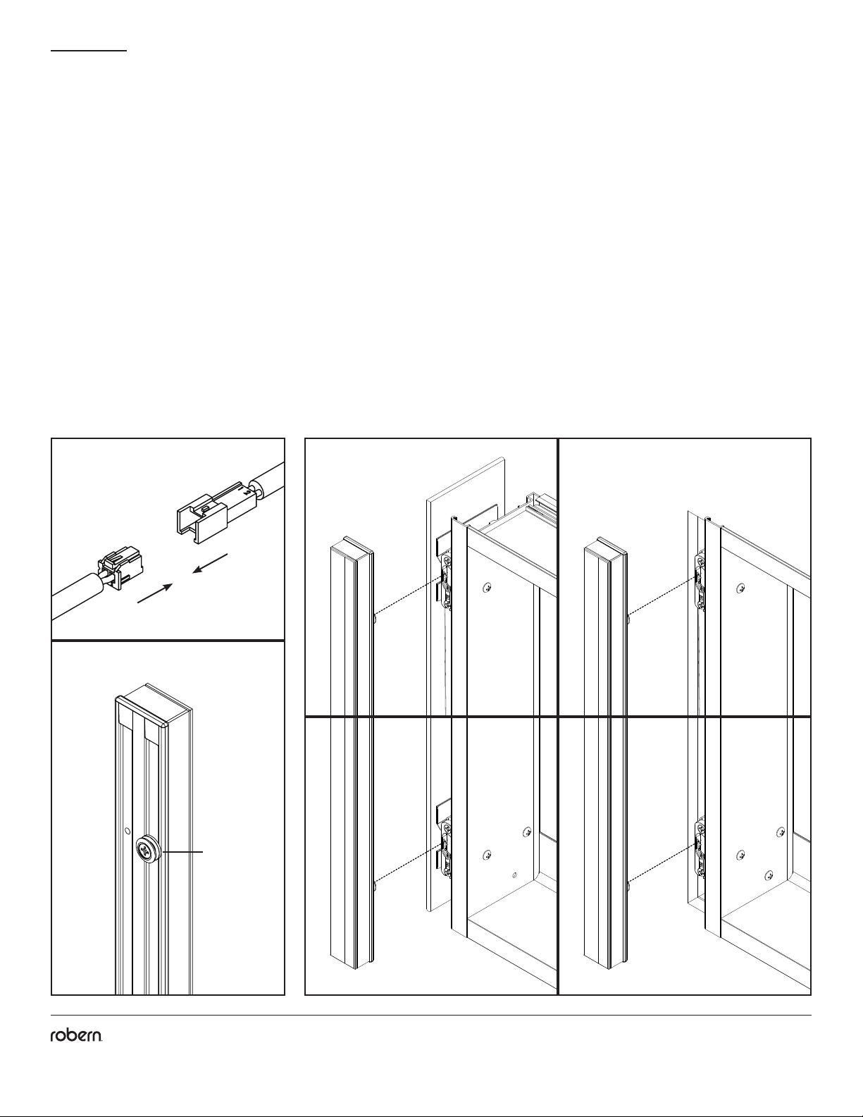
FINAL ASSEMBLY
4. Connect the electrical connector from the light to the electrical low voltage wire connector coming out of the electrical enclosure.
5. Align and insert the buttons on the back of the light into the upper and lower adjustable button receivers [205-3304].
6. Slide the light down until it's completely engaged.
4
3Surface Mount Recess Mount
Button
[211-1351]
Part no. 209-1330 01/06/21
Vesper Edgeline Lights
16
© 2020 Robern, Inc. 701 N. Wilson Ave. Bristol, PA 19007 U.S.A.
800.877.2376 www.robern.com
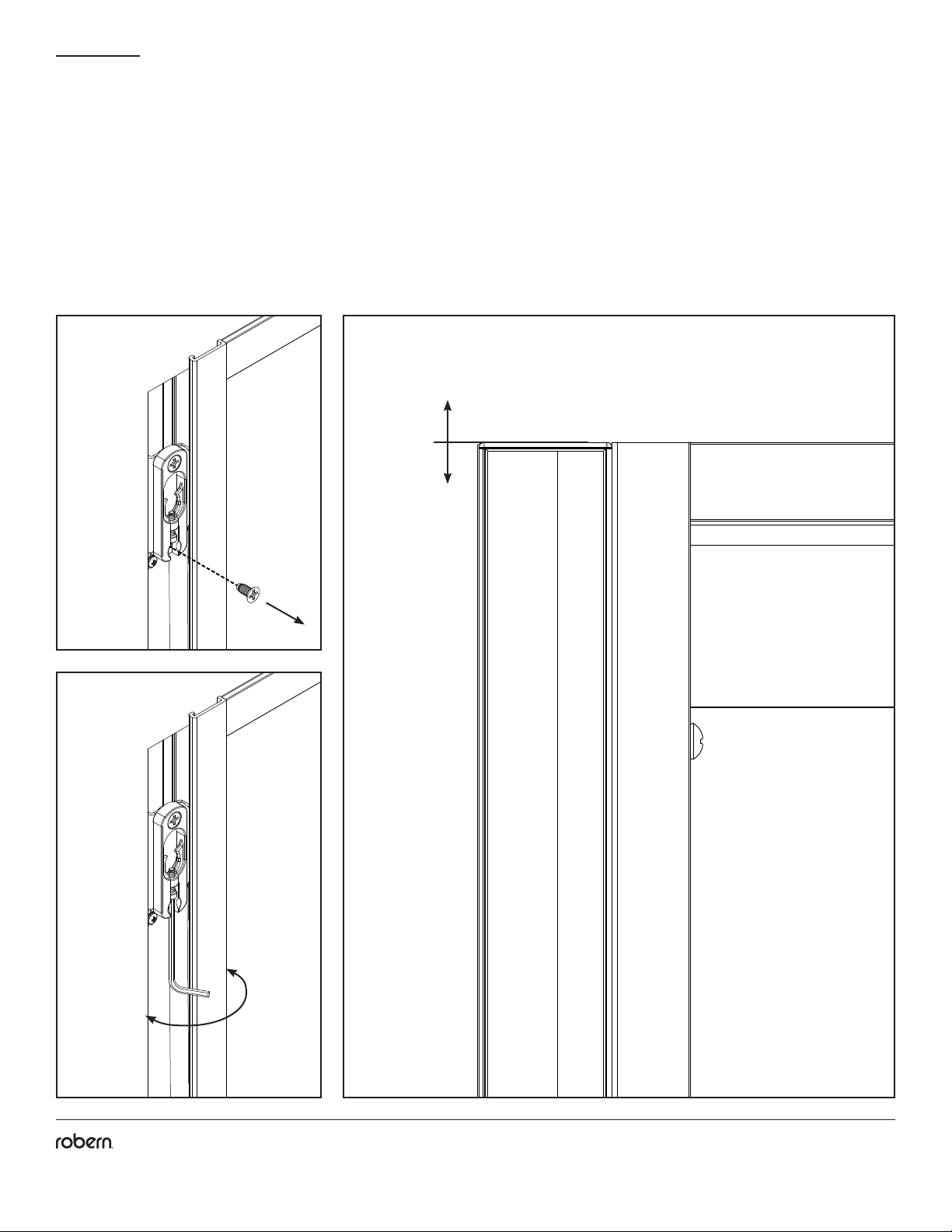
PRODUCT ALIGNMENT
Note: If the top of the light doesn't align with the top of the cabinet, remove the light and set aside in a safe place before proceeding
with the following steps.
1. Remove the lower mounting screw [203-1538] from the adjustable button receiver to access the adjustment screw.
2A. Using the provided Allen key [203-1057] turn the adjustment screw to raise or lower the light into alignment with the cabinet.
2B. Reattach the light and check alignment. Repeated adjustments may be necessary. Once alignment is achieved, reattach the screw
[203-1538] removed in step 1.
2A
1 2B
+
-
+
-

Part no. 209-1330 01/06/21
Vesper Edgeline Lights
17
© 2020 Robern, Inc. 701 N. Wilson Ave. Bristol, PA 19007 U.S.A.
800.877.2376 www.robern.com
PRODUCT ALIGNMENT
3. Adjust the cabinet doors until they align with the lights using the three-way adjustment features in the hinges, adjusted using a #2
Phillips Head screwdriver.
3A. Height: With the hinge slightly closed, you can access the middle screw. This screw will move your door front up and down.
3B. Side to Side/Depth: With the hinge fully extended, you can access the front and back screws. The front screw will adjust the door
from side to side and the rear screw will adjust the door's depth.
4. Press a # 10 screw cap [SS672], provided with each light, onto all exposed screw heads.
5. Press a hole plug [SS134], included with your cabinet hardware, into all open mounting holes.
FINAL ASSEMBLY - CAPS AND PLUGS
PRESS A #10 SCREW CAP [SS672], PROVIDED WITH EACH LIGHT, ONTO ALL EXPOSED SCREW HEADS.
1.
PRESS A HOLE PLUG [SS134], INCLUDED WITH YOUR CABINET HARDWARE, INTO ALL OPEN MOUNTING HOLES.
2.
FINAL ASSEMBLY - CAPS AND PLUGS
PRESS A #10 SCREW CAP [SS672], PROVIDED WITH EACH LIGHT, ONTO ALL EXPOSED SCREW HEADS.
1.
PRESS A HOLE PLUG [SS134], INCLUDED WITH YOUR CABINET HARDWARE, INTO ALL OPEN MOUNTING HOLES.
2.
FINAL ASSEMBLY - CAPS AND PLUGS
PRESS A #10 SCREW CAP [SS672], PROVIDED WITH EACH LIGHT, ONTO ALL EXPOSED SCREW HEADS.
1.
PRESS A HOLE PLUG [SS134], INCLUDED WITH YOUR CABINET HARDWARE, INTO ALL OPEN MOUNTING HOLES.
2.
FINAL ASSEMBLY - CAPS AND PLUGS
PRESS A #10 SCREW CAP [SS672], PROVIDED WITH EACH LIGHT, ONTO ALL EXPOSED SCREW HEADS.
1.
PRESS A HOLE PLUG [SS134], INCLUDED WITH YOUR CABINET HARDWARE, INTO ALL OPEN MOUNTING HOLES.
2.
Surface Mount Recess Mount
SS672
SS134
SS134
SS672
SS672
SS672
3A 3B
Part no. 209-1330 01/06/21
Vesper Edgeline Lights
18
© 2020 Robern, Inc. 701 N. Wilson Ave. Bristol, PA 19007 U.S.A.
800.877.2376 www.robern.com
USE AND MAINTENANCE
CAUTION - RISK OF SHOCK
Risk of personal injury; disconnect power before servicing.
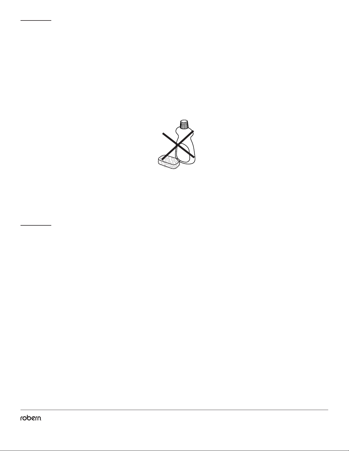
Use only a damp cloth to clean. Ammonia or vinegar-based cleaners can damage the nish.
A 50/50 solution of water and isopropyl alcohol is recommended for cleaning the light xture.
When cleaning, spray the cloth, not the light xture or surround surfaces. Do not use abrasive cleansers on any part of the light xture.
No Ammonia
Sans Ammoniac
Sin Amoniaco
No Vinegar
Sans Vinaigre
Sin Vinagre
WARRANTY
Limited Warranty One Year Term
Robern warrants to the original purchaser that, it will, at its election repair, replace, or make appropriate adjustment to products made
by this company shown to have signicant defects in material or workmanship which are reported to Robern in writing within one (1)
year from the date of delivery. Robern is not responsible for installation costs. The warranty is void in the event the product is damaged
in transit, or if damage or failure is caused by abuse, misuse, abnormal usage, faulty installation, damage in an accident, improper
maintenance, or any repairs other than those authorized by Robern. At the expiration of the one year warranty period, Robern shall be
under no further obligation under any warranty, expressed or implied, including the implied warranty of merchantability. Robern shall
not be liable for any consequential damages arising out of or in connection with the use or performance of its products. Some states
do not allow limitations on how long an implied warranty lasts or do not allow the exclusion or limitation of incidental or consequential
damages, so the above limitation or exclusion may not apply to you. Any liability against Robern under any implied warranty, including
the warranty of merchantability, is expressly limited to the terms of this warranty. Permission to return any merchandise under this
warranty must be authorized by Robern and returned prepaid by the purchaser. Claims under this warranty should be sent directly to
your dealer.
©2020 Robern, Inc.
All rights reserved
No. de pièce / Pieza n.°209-1330 01/06/21
Lampe Vesper Edgeline / Iluminación Vesper Edgeline
1
1
© 2020 Robern, Inc. 701 N. Wilson Ave. Bristol, PA 19007 U.S.A.
800.877.2376 www.robern.com
Cette che d'instructions contient des informations sur
l'installation du Vesper Edgeline Light. Cette série se décline
en plusieurs variantes. Veuillez vous référer à la boîte ou à
l'étiquette du produit pour le numéro de modèle spécique.
Une clé est fournie à la page 18.
Conservez ces instructions pour une utilisation et une
référence futures. Une installation incorrecte annule la
garantie. Inspectez soigneusement la lampe pour tout
dommage. Les produits installés ne peuvent pas être
retournés.
Si vous rencontrez des problèmes avec votre éclairage,
contactez votre revendeur ou directement Robern.
Garantie limitée - Durée d'un an
Esta hoja de instrucciones contiene información sobre cómo
instalar Vesper Edgeline Light. Esta serie viene en muchas
variaciones. Consulte la caja o la etiqueta del producto para
obtener el número de modelo especíco. Se proporciona una
clave en la página 18.
Guarde estas instrucciones para uso futuro y referencia.
Una instalación incorrecta anula la garantía. Inspeccione
cuidadosamente la luz en busca de daños. Los productos
instalados no pueden ser devueltos.
Si tiene algún problema con su luz, comuníquese directamente
con su distribuidor o con Robern.
Garantía limitada: un año
CONTENU CONTENIDO
INFORMATION GÉNÉRALE INFORMACIÓN GENERAL
Outils Nécessaires / Pièces - 3
Assemblage des Supports - 5
Montage des Supports sur l'Armoire - 6
Montage des Supports Entre les Armoires - 7
Accéder au Boîtier Électrique - 8
Installation Encastrée - 9
Installation en Surface - 11
Assemblée Finale - 14
Alignement des Produits - 16
Herramientas Necesarias / Piezas - 3
Montaje de los Soportes - 5
Montaje de los Soportes en el Gabinete - 6
Montaje de los Soportes entre Gabinetes - 7
Acceda a la Caja Eléctrica - 8
Instalación Empotrada - 9
Instalación en Superficie - 11
Asamblea Final - 14
Alineación de Productos - 16
LAMPE VESPER™ EDGELINE
Instructions d'installation
Consignes de sécurité importantes - Conserver ces instructions
ILUMINACIÓN VESPER™ EDGELINE
Instrucciones de instalación
Instrucciones de seguridad importantes - Guarde estas instrucciones
Convient aux emplacements humides /
Adecuadas para ubicaciones húmedas
No. de pièce / Pieza n.°209-1330 01/06/21
Lampe Vesper Edgeline / Iluminación Vesper Edgeline
2
2
© 2020 Robern, Inc. 701 N. Wilson Ave. Bristol, PA 19007 U.S.A.
800.877.2376 www.robern.com
Utilisez le tableau ci-dessous pour savoir comment lire le
numéro de modèle de votre lampe. Ce tableau fait référence
au numéro de modèle des lampes Edgeline de 1-3 / 8 "L x 40"
H avec une nition en métal argenté. Consultez le catalogue
de prix Robern pour une liste complète des numéros de
modèle.
Use la tabla a continuación para aprender a leer su número
de modelo de luz. Este cuadro hace referencia al número de
modelo para un Edgeline Lights de 1-3 / 8 "W x 40" H con un
acabado de metal plateado. Consulte el Libro de precios de
Robern para obtener una lista completa de los números de
modelo.
Numéros de modèle / Números de modelo G L A 40 E L P S 3D
Gamme de produits / Línea de producto G = Vesper
L = Lumières / Luces
A = 1-3/8" / 35 mm
30 = 30" / 762 mm
36 = 36" / 914 mm
40 = 39-3/8" / 1000 mm
E = Edgeline
L = LED
3 = 3000K
P = Pair Lamp
D = Dimmable / Regulable
S = argent / Plata
Nom de lumière / Nombre de luz
Largeur / Anchura
Quantité de lampes / Cantidad de lámparas
Type de moteur / Tipo de motor
Catégorie / Catégorie
Type de lampe / Tipo de lámpara
Température de couleur / Temperatura del color
la taille / Altura
Couleur principale du corps / Color del cuerpo principal
Robern recommande d'utiliser le gradateur Maestro® C • L®
de LUTRON®, modèle MACL-153M.
http://www.lutron.com/TechnicalDocumentLibrary/369613a.pdf
D'autres gradateurs de commande à LED peuvent fonctionner
avec ce produit mais n'ont pas été testés ou vériés. Il est
recommandé de laisser le variateur à la portée de votre miroir
an de pouvoir régler la luminosité.
Pour un fonctionnement tout ou rien (sans gradation), un
interrupteur mural standard peut remplacer le gradateur.
Para los modelos regulables, Robern recomienda el Atenuador
Maestro® C • L® de LUTRON®, Modelo # MACL-153M.
http://www.lutron.com/TechnicalDocumentLibrary/369613a.pdf
Otros atenuadores de control LED pueden funcionar con
este producto pero no han sido probados o vericados. Se
recomienda que el atenuador esté al alcance de su espejo
para que pueda ajustar el brillo.
Para la operación de encendido / apagado (sin atenuación), se
puede sustituir un interruptor de pared estándar en lugar del
atenuador.
RECOMMANDATIONS AU
GRADATEUR
RECOMENDACIONES DEL
INTERRUPTOR DE ATENUACIÓN
NUMÉROS DE MODÈLE NÚMEROS DE MODELO
Table of contents
Popular Lighting Equipment manuals by other brands

Altman
Altman GALLERY SERIES quick start guide

AEG
AEG A18SL Original instructions

Springtree
Springtree HD202 WW user manual

Daisy
Daisy Below Ground Pool Cover Box installation guide

Hunza
Hunza ULTRA 12 SPOT installation instructions

olympia electronics
olympia electronics OLY-1004/LT/WP installation instructions

Fermob
Fermob aplo h24 quick start guide

ELUSIVE WILDLIFE
ELUSIVE WILDLIFE Blind Sider-X2 manual

Beamz Pro
Beamz Pro BAC306 instruction manual

Lightolier
Lightolier Lighting Systems Baselyte-BSL3 Specification sheet

Current
Current Dual-Lite PLD10 Installation, operation and service instructions

American DJ
American DJ Electra 250 User instruction


