Altman GALLERY SERIES User manual

QUICK START GUIDE
GALLERY_QUICK_START_20220114
GALLERY SERIES LED LUMINAIRES
QUICK START GUIDE

Page 2
Gallery Series Quick Start Guide
Have a question regarding this guide?
Note: Information contained in this document may not be duplicated in full or in part by any person without prior written approval
of Altman Lighting Its sole purpose is to provide the user with conceptual information on the equipment mentioned. The use of this
document for all other purposes is specifically prohibited.
The material in this manual is for information purposes only and is subject to change without notice. Altman Lighting assumes no
responsibility for any errors or omissions which may appear in this manual. For comments and suggestions regarding corrections
and/or updates to this manual, please visit the Altman Lighting web site at www.altmanlighting.com or contact your nearest Altman
Lighting Regional Manager.
El contenido de este manual es solamente para información y está sujeto a cambios sin previo aviso. Altman Lighting no asume
responsabilidad por errores o omisiones que puedan aparecer. Cualquier comentario, sugerencia o corrección con respecto a este
manual, favor de dirijirlo a la oficina de Altman Lighting más cercana.
Der Inhalt dieses Handbuches ist nur für Informationszwecke gedacht, Aenderungen sind vorbehalten. Altman Lighting uebernimmt
keine Verantwortung für Fehler oder Irrtuemer, die in diesem Handbuch auftreten. FürBemerkungen und Verbesserungsvorschlaege
oder Vorschlaege in Bezug auf Korrekturen und/oder Aktualisierungen in diesem Handbuch, moechten wir Sie bitten, Kontakt mit der
naechsten Altman Lighting Niederlassung aufzunehmen.
Should you have a suggestion or question regarding your Altman Lighting product, we would love to hear from you.
You can reach us at:
Altman Lighting
1400 East 66th Ave.
Denver, CO. 80229
+1 (303) 500-7072
www.altmanlighting.com
Altman Lighting continually engages in research related to product improvement. New materials, production methods and design
refinements are introduced into existing products without notice as a routine expression of the philosophy. For this reason any current
Altman Lighting product may differ in some respect from its published description, but will always equal or exceed the original design
specifications unless otherwise noted.
Our Commitment
Preface
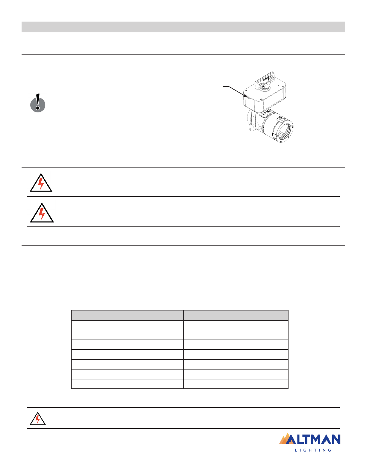
The document provides basic information on installation and operational instructions for a quali-
fied, trained installer. These instructions provide information for the following product:
Gallery Series LED Luminaires
Additional product information can be found on our web site at
www.altmanlighting.com or by scanning the QR code to the right.
Gallery Quick Start Guide
©2022 Altman Lighting. All rights reserved.
Document Number: 49-0235
Version as of: 2022-JANUARY-14

Page 3
Gallery Series Quick Start Guide
When using electrical equipment, basic safety precautions should always be followed including the following:
1. READ AND FOLLOW ALL SAFETY INSTRUCTIONS.
2. Do not use outdoors unless the product is specified to operate in outdoor environments.
3. Do not mount near gas or electric heaters.
4. Equipment should be mounted in locations and at heights where it will not readily be subjected to tampering by
unauthorized personnel.
5. The use of accessory equipment not recommended by the manufacturer may cause an unsafe condition.
6. Do not use this equipment for other than intended use.
7. Refer service to qualified personnel.
SAVE THESE INSTRUCTIONS.
WARNING: You must have access to a main circuit breaker or other power disconnect device before installing
any wiring. Be sure that power is disconnected by removing fuses or turning the main circuit breaker off before
installation. Installing the device with power on may expose you to dangerous voltages and damage the device. A
qualified electrician must perform this installation.
WARNING: Refer to National Electrical Code® and local codes for cable specifications. Failure to use proper
cable can result in damage to equipment or danger to personnel.
WARNING: This equipment is intended for installation in accordance with the National Electric Code® and
local regulations. Before any electrical work is performed, disconnect power at the circuit breaker or remove the fuse
to avoid shock or damage to the control. It is recommended that a qualified electrician perform this installation.
WARNING: This Lighting Fixture is NOT for residential installation or use.
WARNING: The structure where fixture(s) is to be mounted must be capable of supporting the weight of
the fixture and its accessories. This fixture is for temporary, portable mounting only.
WARNING: The light source contained in this luminaire shall only be replaced by the manufacturer or his
service agent or a similar qualified person.
THIS PRODUCT MUST BE INSTALLED IN ACCORDANCE WITH THE APPLICABLE INSTALLATION CODE
BY A PERSON FAMILIAR WITH THE CONSTRUCTION AND OPERATION OF THE PRODUCT AND THE
HAZARDS INVOLVED.
CE PRODUIT DOIT ÊTRE INSTALLÉ SELON LE CODE D’INSTALLATION PERTINENT, PAR UNE
PERSONNE.
CONSULT A QUALIFIED ELECTRICIAN TO ENSURE CORRECT BRANCH CIRCUIT CONDUCTOR.
CONSULTER UN ÉLECTRICIEN QUALIFIÉ POUR VOUS ASSURER QUE LES CONDUCTEURS DE LA
DÉRIVATION SONT ADÉQUATS.
Product Safety Notices
Warnings
Important Information

Page 4
Gallery Series Quick Start Guide
FCC Notice
This equipment has been tested and found to comply with the limits for a Class A digital device, pursuant to
part 15 of the FCC Rules. These limits are designed to provide reasonable protection against harmful interfer-
ence when the equipment is operated in a commercial environment. This equipment generates, uses, and can
radiate radio frequency energy and, if not installed and used in accordance with the instruction manual, may
cause harmful interference to radio communications.
Operation of this equipment in a residential area is likely to cause harmful interference in which case the user
will be required to correct the interference at his own expense.
Altman Lighting Product Warranty
Altman Lighting, Inc., a subsidiary of Altman Stage Lighting Company, Inc., herein referred to as Altman, war-
rants each new product (except for spare parts or products Altman does not manufacture) for a period of FIVE
(5) years and ONE (1) day from date of shipment to correct by repair or replacement any part defect due to faulty
material or workmanship.
Altman warrants for NINETY (90) days any spare part it manufactures. On spare parts or products Altman does
not manufacture, including, but not limited to, lamps, sockets, lenses, roundels, electronics, ignitors, ballasts,
etc.; Altman will grant the same warranty given Altman by its vendors. Altman assumes no responsibility for
damage or faulty performance caused by misuse, improper installation, careless handling or where repairs have
been attempted by others. This warranty is in lieu of all warranties or guarantees expressed or implied and no
representative or person is authorized to assume Altman any other liability with the sale of Altman’s products.
Altman assumes no responsibility for damage or faulty performance caused by misuse, improper
installation, careless handling or where repairs have been attempted by others.
This warranty is in lieu of all warranties or guarantees expressed or implied and no representative or person is
authorized to assume Altman any other liability with the sale of Altman’s products.
Warranty Terms

Page 5
Gallery Series Quick Start Guide
Table Of Contents
Important Information 3
Altman Lighting Product Warranty 4
Table Of Contents 5
Installation & Set Up 6
Top Box Overview 6
Gallery Gate Installation 7
Gallery Lens Installation 7
Safety Cable Installation 8
Power Requirements 8
Connecting Power 8
Mains Dimming Version 9
Smart Track Models 10
Portable Models 10
0-10V Controlled Models (Sink Current) 11
Canopy / Pendant Mount Models 12
Connecting Data (DMX Models) 13
RJ45 / XLR Connector Wiring 13
Terminal Block (Phoenix Connector) Wiring 14
Setting a DMX Address via RDM 15
Operation 16
Luminaire Features 16
Cleaning And Care 20

Page 6
Gallery Series Quick Start Guide
Installation & Set Up
Top Box Overview
There are several mounting configurations for the Gallery Series LED Luminaires:
• Portable - C-Clamp / Unistrut
• Smart Track / Track
• Ceiling / Pendant
The model(s) purchased determines how the unit can be mounted. Figure 5 shows the features and connections
on the two versions of the Gallery Series Luminaire top boxes.
C-Clamp / Unistrut Mounting Point
(mounting hole 1/2-in. / 12.7 mm)
DMX In / Out
(RJ45 connections)
IEC Connection (AC Input)*
Portable C-Clamp / Unistrut Mount Models
Note: *One molded VLock IEC to Edison 2 meter (6’-6”) cable
(part number 54-VL012405200) is included with portable units.
Track Adapter
Safety Cable Anchor Point
(same for all models)
Smart Track / Track Mount Models
Ceiling Mount
Ceiling / Pendant Mount Models
Pendant Mount
Stem
NOTES: Only top boxes shown for clarity.
Top boxes are not removable (from standard
models) and cannot be remotely located.
Figure 5: Top Box Overview - Features
Safety Cable Anchor Point
(same for all models)
Portable Remote Top Box with C-Clamp / Unistrut Mount Models
C-Clamp / Unistrut Mounting Point
(mounting hole 1/2-in. / 12.7 mm)
1 Meter Cable that goes between the
Remote Gallery Engine and Remote
Top Box
Remote Gallery Engine Mount
Safety Cable Anchor Point
(same for all models)
Refer to “Portable Models” on
page 10 for more information.
Refer to “Smart Track Models”
on page 10 for more
information.
Refer to “Ceiling / Pendant Models”
on page 12 for more information.

Page 7
Gallery Series Quick Start Guide
Gallery Gate Installation
The provided Gallery Gate should be installed as shown in Figure 2.
To connect Gallery Gate to Gallery LED Engine:
Step 1. Unscrew the Accessory Cover Lock from the Gallery
LED Engine.
Step 2. Slide the Gallery Gate onto the Gallery LED Engine.
Step 3. Install the Accessory Cover Lock back onto the
Gallery LED Engine.
Note: The Gallery Gate is only supplied and required for the 25°- 50° Short Zoom Lens and 15°- 35° Long Zoom
Lens Luminaires
Accessory Cover Lock
Gallery Gate Assembly:
GALGALT*
Gobo Slot Cover
Gallery LED Engine
Gallery Lens Installation
Figure 2: Gallery Gate - Overview
The provided Gallery Lens should be installed as shown in Figure 3 and Figure 4.
To connect Gallery Lens:
Step 1. Unscrew the Accessory Cover Lock from the Gallery LED Engine
Step 2. Slide the Gallery Lens onto the Gallery LED Engine
Step 3. Install the Accessory Cover Lock back onto the Gallery LED Engine
Note: The 25°- 50° Short Zoom Lens and 15°- 35° Long Zoom Lens Luminaires will attach to the Gallery Gate
Figure 3: Gallery 25°- 50° Short Zoom Lens - Overview Figure 4: Gallery Beam Wash Lens - Overview
Gallery LED Engine
Gallery Gate Assembly:
GALGALT*
Accessory Cover Lock
Gallery 25°-50° Short Zoom Lens Tube:
GAL2550LT*
Accessory Cover Lock
Gallery LED Engine
Gallery Beam Wash Zoom Lens Tube:
GALBWLT*
Note: The Gallery Gate needs to be installed with the Shutter
side facing the 25°- 50° Short Zoom Lens or 15°- 35° Long
Zoom Lens. Shutter x4

Page 8
Gallery Series Quick Start Guide
Power Requirements
WARNING! The Gallery Series LED Luminaires should be connected to a constant circuit or a relay device. It should
never be connected to a dimmer or circuit controlled by a dimmer unless the unit is specifically designed to do so
(MAINS dimming models - 120VAC only). Read this section carefully on how to properly connect your fixture.
WARNING! All Gallery Series LED Luminaires are shipped prewired from the factory. The wiring information in
Table 1 is shown for field wiring information and must be performed by a qualified and licensed electrician. Before
performing any field wiring, refer to and read the warnings contained in “Important Information” on page 3.
Connecting Power
Units are powered in one of two ways depending on the model(s) purchased.
• Direct connection to a AC power source for the portable unit via their IEC to Edison input cable (Portablemodels that
are mounted with a C Clamp or Unistrut).
• Direct connection to the powered track (Track Mount / Smart Track Models or Ceiling / Pendant Models) Field wiring
of the fixture is straight forward. A total of three wires/conductors need to be brought to the unit. The following wiring
scheme, as shown in Table 1, is required for direct connection models.
Wire Color (120V Models) Purpose
Black Main / (L)ine
White (N)eutral
Green Ground / Earth
Wire Color (100- 240VAVC Models) Purpose
Brown Main / (L)ine
Blue (N)eutral
Green / Yellow Ground / Earth
Table 1: AC Input Wiring
IMPORTANT! All Gallery Series LED Luminaires must be connected to and properly grounded to an viable earth
ground.
Safety Cable Installation
The provided Mini Safety Cable (MSC) should be installed as shown in Figure 5.
Safety Cable Anchor Point
Figure 5: Gallery Safety Cable - Overview
IMPORTANT! The safety cable (supplied with
unit) should be used and may be required by
local and/or national codes when hanging this
luminaire. The mounting structure must be
capable of supporting the weight of the fixture,
lens, cabling, any accessories, etc.

Page 9
Gallery Series Quick Start Guide
Gallery Series LED Luminaires are available in a 120VAC Mains Dim version which is achieved with standard
TRIAC-Based incandescent dimmers (see Table 2, “Compatible Mains Dimmers,” on page 11) that “chop” the
AC voltage or with standard ELV (electronic low-voltage) dimmers.
Phase Cut AC Sine Wave
(from Dimmer to Fixture)
Normal AC Sine Wave
(from Source to Dimmer)
Figure 6: Phase Cut Sine Wave Example
Manufacturer Dimmer Model Manufacturer Dimmer Model
Lutron
S-603PG
Leviton
IP-106-1LZ
DVCL-153P 6631-2
DV-600P VPE06
TGCL-153P 6683-IW
S-600P 6161
DVELV-303P 6633-P
SELV-300P IPE04
TG-600P
Cooper
DLC03P
CT-103P SLC03P
MAELV-600 DAL06P
FAELV-500
Strand Lighting
C21 350uS
Lightolier ZP260QEW A21 IGBT
ETC D Series A21 SCR
WARNING! Phase-Cut Dimmers are only available for 120VAC systems. The use of any other
type of dimmer will damage the unit and void the product’s warranty. Table 2 represents a
number of manufacturers dimmers that have been tested with the product. As this list represents
some of the larger dimmer manufacturers it is recommended when utilizing an alternate dim-
ming manufacturer that the Gallery Series Luminaire is tested with any alternate dimmer prior
to utilization. Please note that the majority of phase-cut dimmers tested have resulted in proper
dimming performance. For additional information, please contact customer service.
Table 2: Compatible Mains Dimmer
Mains Dimming Version

Page 10
Gallery Series Quick Start Guide
Smart Track Models
To connect Smart Track models to track:
Step 1. If not done at factory, connect AC
wiring as shown in Figure 7. Also refer
to Table 1 “Input Wiring on page 8
Neutral
Main / Line
Ground /
Earth
Figure 7: Track Adapter Power
Wiring
Step 2. As shown in Figure 8, connect fixture
to track as follows:
A. Turn Knob A Clockwise 90 Degrees for physical
mechanical attachment.
B. Turn Knob B Clockwise 90 Degrees for circuit #1
power
C. Turn Knob B Counterclockwise 90 Degrees for
circuit #2 power.
IMPORTANT! Ensure that the track head is fully seated into the track prior to moving to the next step.
Portable Models
Portable models are supplied with a locking IEC power input connector. Similar to other electronic devices. This
type of connector is used due to its reliability and inability to cross the main / neutral / ground connections. IEC
ac input cables are readily available through most electrical /electronic retailers around the world. One molded
VLock IEC to Edison 2 meter (6’-6”) cable (part number 54-VL012405200) is included with portable units
Note: Some models are Mains dimmable models. These units are for 120VAC markets only and a list of
approved dimmers is listed in Table 2 on page 7.
To connect power to Portable Models:
Step 1. Make sure the AC cable is not connected to an AC power source.
Step 2. As illustrated in Figure 9, position AC input cable in direct relation to the IEC connector on the side
luminaire top box assembly.
Portable Model Top Box
IEC Connector (AC Input)
NOTES:
• Luminaire not shown for clarity.
• Top boxes are not removable (from standard models)
and cannot be remotely located.
• Remote top box configurations are available for portable
units only. Remote top box models must be ordered
specifically as a remote top box set up. Remote top box
units have a one (1) meter cable between the luminaire
engine and top box. Refer to the Altman Lighting web
site www.altmanlighting.com for more details.
Figure 9: IEC Connector - Portable Models
Step 3. Press AC input cable IEC connector firmly into IEC connector on top box assembly.
Step 4. The luminaire is now ready to connect to an AC source.
Figure 8: Installing Fixture on
Track

Page 11
Gallery Series Quick Start Guide
0-10V Controlled Models (Sink Current)
Gallery Series LED Luminaires’ 0-10V drivers only operate with dimmers that sink current. They are not de-
signed to operate with 0-10V controls systems that source current, as used in theatrical and entertainment
systems. Developed in the 1980’s, the 0-10V sinking current controls method is adopted by the International
Electrotechnical Commission (IEC) as apart of the IEC 60929 Annex E standard.
The method to dim the output current of the driver is done via the +Dim/-Dim signal lines. This input responds
to a 0-10V signal, delivering 1%-100% of the output for the luminaire.
Compatible 0-10V Dimmers include but are not limited to:
• Lutron: Nova Series
• Lutron: Diva Series
• Leviton: Illuma Tech Series.
IMPORTANT! As all 0-10 Volt dimmers offer different features and options please consult the
dimmer manufacturers wiring guide for additional information when wiring to 0-10V operated
Gallery Series LED Luminaires.
Black or Brown (Line)
White or Blue (Neutral)
Green or Green/ Yellow
(Ground / Earth)
Purple (Dim+)
Gray / Pink (Dim-)
Wire Color Signal
Purple Dim - Positive (+)
Gray Dim - Negative (-)
IMPORTANT! The 2020 National Electrical Code® (NEC) (NFPA-70) contains a new requirement
in section 410.69 that disallows the use of insulation colors reserved for the grounded branch
circuit conductor (white or gray) or the equipment grounding conductor (green or green with a
yellow stripe) for a field-connected control circuit conductor. A decision was made that pink will
be an acceptable replacement for gray control conductor. This requirement will become effective
on January 1, 2022. See Table 4 for new 0-10V Wiring
Table 3: Before January 1, 2022 0-10V Wirng
Wire Color Signal
Purple Dim - Positive (+)
Pink Dim - Negative (-)
Table 4: After January 1, 2022 0-10V Wirng
Figure 10: 0-10V and Power Wiring

Page 12
Gallery Series Quick Start Guide
Canopy / Pendant Mount Models
IMPORTANT! Ceiling junction box and junction box screws are not included with Gallery Series
LED Luminaires and are by others.
WARNING! Canopy / pendant mount models must be installed by qualified professional installer
and should be done in accordance with local and national codes.
WARNING! Make sure power to the junction box is completely disconnected. Failure to do so
could lead to serious injury or death.
To wire and install canopy / pendant mounted models:
Step 1. Install Gallery Series LED Luminaires Mounting Flange to ceiling junction box. Ceiling junction box
is octagon-style box (by others). Mounting hole spacing is 3.5-inches (88.9 mm).
Step 2. Connect wiring to fixture. Refer to “Connecting Power” on page 8 or “0-10V Controlled Models
(Sink Current)” on page 14 as applicable
Step 3. Align fixture bottom mounting flange with top mounting flange screws.
Bottom Mounting Flange
3.5IN / 88.9 MM
Flange Screw (x2)
Top Mounting Flange
(Mounts to Junction Box)
Step 4. Turn clockwise securing the unit to top mounting flange.
Figure 11: Canopy / Pendant Mount
Step 5. Tighten flange screws.

Page 13
Gallery Series Quick Start Guide
Connecting Data (DMX Models)
Gallery Canopy or Pendent DMX controlled models offer a connection block (Figure 12) inside the luminaire’s
canopy. For portable units (refer to “RJ45 / XLR Connectors”).
Basic DMX512 installation consists of connecting multiple DMX controlled Gallery LED Luminaires together
(up to 32 Total devices per DMX string) in “daisy-chain” fashion. A cable runs from the DMX512 control
source to the DMX INPUT connection on the first luminaire.
From the DMX OUTPUT of the luminaire another cable runs to the DMX IN connection on the next luminaire or
other DMX512 device to be controlled.
At the end of each DMX Daisy chain, it is highly recommended that a DMX TERMINATOR (Altman
Lighting part number DMX-MPHX-TERM for the connectors shown in Table 2) is utilized on the
last luminaire (or device) in the chain.
All Canopy and Pendant units will come pre-wired from the factory with the Phoenix connector
installed and there is a spare set sent for Customer Wiring. On Pendant style fixtures (with a stem
mount) this connector must be removed prior to threading cable through the mounting stem and
then reinstalled. These connectors are multi-use and highly recommended for DMX wiring use.
Phoenix Connector Installation
RJ45 / XLR Connector Wiring
For information on RJ45 connectors for DMX Input / Output, refer to Table 5 on page 13 for RJ45 and XLR
connector wiring.
DMX Connections - RJ45 and XLR Connectors
DMX Signal RJ45 Connector XLR Connector
Common (Drain) Pin 7 Pin 1
DMX - Pin 2 Pin 2
DMX + Pin 1 Pin 3
Only those pins shown are used. Remaining pins on RJ45 and XLR connectors are not used.
(A) Insert and Hold small,
flat screwdriver into slot to
open wire way
(B) Insert CAT 5 DMX Cable into Wire
way. Strip wire to 0.25-in / 6.5 mm.
Figure 12: Canopy / Pendant Connection Block
Table 5: RJ45 and XLR Connectors

Page 14
Gallery Series Quick Start Guide
DMX
Connection Wire Color Signal
DMX Input
White / Brown Common
White / Orange Data In (+)
Orange Data In (-)
DMX Output
Green Data Out (-)
White / Green Data Out (+)
Brown Common
Terminal Block (Phoenix Connector) Wiring
(Common) - Pin 1 - Brown
(DMX Out +) - Pin 2 - White / Green
(DMX Out -)- Pin 3 - Green
DMX Output WiringDMX Output Wiring
(Common) - Pin 3
(DMX Out +) - Pin 2
(DMX Out -)- Pin 1
Customer (Building) Wiring
Factory (Fixture) Wiring
Factory
Wired Connection Customer
Connection Connection
Male
Pin 1 (Left)
Female
Pin 3 (Right)
Pin 2 (Center) Pin 2 (Center)
Pin 3 (Right) Pin 1 (Left)
Female
Pin 1 (Left)
Male
Pin 3 (Right)
Pin 2 (Center) Pin 2 (Center)
Pin 3 (Right) Pin 1 (Left)
• All pin information is read from left to right from the back of the connector (looking at wiring inlet).
• (DMX Version Ceiling mount) One (1) piece of Category 5 Belden 1592A cable for all data connec-
tivity. Three (3) of the conductors are used for data input and three (3) conductors for data output.
Note, the White/Blue & Blue conductors are not used. Both Data Input and Output utilize a Phoenix
Contact 3 position terminal block for use with 20-24 AWG.
Part # 51-1709459
DMX Input WiringDMX Input Wiring
(Common) - Pin 1 - White / Brown
(DMX In +) - Pin 2 - White / Orange
(DMX In -) - Pin 3 - Orange
(Common) - Pin 3
(DMX In +) - Pin 2
(DMX In -) - Pin 1
Factory (Fixture) Wiring
Customer (Building) Wiring
Part # 51-1709459
Part # 51-1709451
Part # 51-1709451
Figure 13: DMX Wiring

Page 15
Gallery Series Quick Start Guide
Setting a DMX Address via RDM
Gallery Series LED Luminaires are full featured Remote Device Management (RDM) compliant. All DMX
and Luminaire settings are programmed via a RDM ANSI E1.20 complaint device. As many of the RDM
devices and software work differently please consult the RDM programmer manufacturer for specific
operational instructions. Table 6 on page 18 shows the list of the settings and features that can be set via
RDM.
Note: The entire DMX infrastructure must be RDM compliant in order to achieve system-wide
RDM functionality.
Item Value Additional Values
RDM Protocol Version 0100
Device Model ID LED Driver 40W
Product Category Specialized LED Dimmer
Boot Version 0.00
Software Version ID V000001.12
DMX 512 Start Address 1 (default) Settings between 1 and 512
DMX Foot Print 1 (default)
Manufacturer Label Altman
Dimming Curve Linear (default) Logarithmic
Table 6: DMX Addressing

Page 16
Gallery Series Quick Start Guide
Operation
Luminaire Features
This section will cover the unique features of the various models. Some features - as described in this
section - may or may not be applicable to all models. Each section will let you know what models this
feature is applicable to a fixture or series of fixtures.
Focus Button
Each DMX Model is equipped with a “focus button” located on the top box assembly on the luminaire head
side. This button is programmed for full on/off control of the luminaire whether DMX is active or inactive.
Pressing this button will bring the luminaire to full, if off or off, if at full. If the DMX system is active and the
DMX Value is changed from its current value, the prevailing DMX signal will then take control of the
luminaire.
Note: Any change in the DMX value will over ride the focus button (last action takes precedence).
Zoom Spot Models
Gallery Series LED Luminaires fitted with a short or long zoom lens, has the following features:
• User-settable and lockable zoom and focus control
• 4-blade shutter system (set on two planes)
• Gobo slot for E-size gobos measuring 37.5 mm OD with a 28 mm image area. Gobo holder is included
with all zoom spot models and can be purchased as an additional accessory.
• End of lens tube accessory holder (same for all models, see “Accessory Holder - All Models” on page 19)
Zoom and Focus Control
Zoom and focus is easily accomplished by the two knobs located on the zoom spot lens tube. The front
knob (towards the end of the lens tube) controls the fixture’s zoom / beam angle. The rear knob (closest to
the LED engine) controls the focus of the beam. Refer to Figure 14.
To change the fixture’s beam angle, simply loosen (do not remove) the zoom / beam angle knob and set
as desired. Re tighten by hand once desired beam angle is achieved. Repeat this for the focus of the
fixture.
Note: Keeping the lens knobs loose and slightly snug will allow smooth movement of the lenses
along the lens tube when making adjustments. Loosening the knobs too much will make fine/pre-
cision adjustments difficult and may misalign the lenses and give poor focus adjustment through
the focus range.

Page 17
Gallery Series Quick Start Guide
15°-35° Degree Zoom Basic Setting
Narrow (15° Degrees)
Wide (35° Degrees)
25°-50° Degree Zoom Basic Setting
Narrow (25° Degrees)
Wide (50° Degrees)
Altman Gallery Zoom Gallery 15°-35°
Front of Luminaire
Altman Gallery Zoom Gallery 25°-50°
Front of Luminaire
AB
C
Notes:
(A) Focus Knob
(B) Zoom / Beam Angle Knob
(C) All zoom lens tubes are equipped with a graduated scale.
Side of Luminaire
Bottom of Luminaire
Figure 14: Zoom Spot Models - Beam Control
4-Blade Shutter
Gallery Series LED Luminaires with zoom spot lenses have a gate assembly that contains four-blade
shutters that can be moved by hand in and out of the beam for shutter cuts. The can moved as needed
either straight out (or in) or at an angle. Figure 15 shows the gate and the four shutter blade handles.
* Gate Assembly Notes:
• Gate Assembly must be installed with shutter blades
closest to lens tube for proper focusing and optimal
performance.
• Gate Assembly can rotate 360 degrees for gobo or shut-
ter cuts.
Figure 15: Zoom Spot Models - Shutter Blades
Gobo Slot
Gallery Series LED Luminaires with zoom spot lenses offer a gobo slot (Figure 15) to hold one E-size
gobo with the dimensions of 37.5 mm OD with a 28 mm image area. Gobo holder is included with all zoom
spot models and can be purchased as an additional accessory.
IMPORTANT! Please note that some gobos, depending upon their reflectivity level may need to be blackened in order
to obtain superior projections. Additional beam shaping is obtained through the four (4) integrated shutters.
Lens Tube
Shutter Blade (x4)
Gate Assembly
Gobo Slot
LED Engine
Note: Luminaire shown in exploded view for clarity. Track
model shown, same for all zoom spot models.

Page 18
Gallery Series Quick Start Guide
Beam Wash Models
Beam wash models offer a variable beam angle of 15 to 60 degrees and a end of lens accessory holder
(see “Accessory Holder - All Models” on page 19 for more information on the accessory holder).
Beam Angle Adjustment
Gallery Series LED Luminaires that have the beam wash lens are designed and are ideal to project a soft
edge, even beam of light. For beam wash models, beam shaping is achieved through external, four-flap
barn doors (sold separately).
To adjust the beam angle, simply loosen, do not remove, the beam angle knob as illustrated in Figure 15.
Once the desired angle is achieved, re-tighten the beam angle knob.
Note: Keeping the beam angle knob loose and slightly snug will allow smooth movement of the
lens along the lens tube when making adjustments. Loosening the knob too much will make fine/
precision adjustments difficult and may misalign the lens.
Altman Gallery Beam Wash
Beam Wash Setting
Spot Position (15° Degrees)
Altman Gallery Beam Wash
Flood Position (60° Degrees)
Front of Luminaire
Front of Luminaire
Beam Angle Knob
Figure 16: Beam Wash Models - Beam Angle Adjustment
Flood Models
Flood models offer a fixed beam angle of 85 degrees and a end of lens accessory holder (“Accessory Holder -
All Models” on page 19) below for more information on the accessory holder). For flood models, beam shap-
ing is achieved through external, four-flap barn doors (sold separately).

Page 19
Gallery Series Quick Start Guide
Accessory Holder - All Models
All Gallery Series LED Luminaires have a end of lens accessory holder. This holder is easily opened to
accept such optional accessories (all sold separately or by others) as:
• 4-Flap Barn Doors
• Top Hat
• Half Top Hat
• Color (Gel) Frame
To open the accessory holder, as illustrated in Figure 16, remove the thumb screw holding the accessory
holder clamp and insert the accessory. Once the accessory is inserted, reinstall the accessory holder
clamp and screw.
Accessory Holder Clamp
Accessory Holder Thumb Screw
Pan & Tilt - All Models
Note: Beam Wash model shown,
same for all models.
All Gallery Series LED Luminaires can have their pan and tilt set by hand (without the use of tools).
To adjust pan or tilt, loosen (do not remove) thumb screw or knob as indicated in Figure 18 and adjust pan
or tilt as desired. Once positioned as desired, re-tighten, by hand or tool (see note on tilt knob), the thumb
screw or knob. Do not over tighten!
Pan Thumb Screw Pan Stop (See Note Below)
Tilt Knob (See Note Below)
*A small screwdriver can
be inserted into knob hole
to tighten if desired.
Note: All Gallery Series LED Luminaires are fitted with pan and tilt stop studs. The stops prevent
the fixture head from panning or tilting beyonds it limits for internal wiring travel. It is important
that these stops are never removed from the fixture or internal wiring damage may occur.
Figure 18: Fixture Pan & Tilt
Figure 17: Accessory Holder - All Models

Page 20
Gallery Series Quick Start Guide
Cleaning And Care
Being a solid-state fixture, and unlike most fixtures, the Gallery Series LED Luminaire requires very little rou-
tine maintenance by the user. This section covers portions of the luminaire that can be removed for cleaning.
The Gallery Series Luminaire LED requires special care when it comes to cleaning the front reflector assembly.
Additional care needs to be taken with the plastic components because they are much easier to scratch or
damagethan glass.
The following is a list of cleaning materials required to care for your Gallery Series LED Luminaire:
• Lint free lens tissue
• Lint or powder free gloves
• Reagent grade isopropyl alcohol*
• A mild soap solution.
WARNING! All cleaning should be performed with power completely removed from the luminaire. Never remove protec-
tive covers when luminaire is powered. Wear appropriate protective eye wear and gloves when cleaning the fixture.
All service and maintenance, other than described herein, should be performed by a qualified technician or Authorized
Service Center. AT NO TIME SHOULD THE LED BE TOUCHED.
Reagent grade isopropyl alcohol is good to use on the Gallery Series LED Luminaire plastic optics
with anti-reflection coatings.
If the lens is still dirty after using isopropyl alcohol, for instance if fingerprints or oil is just redistributed and
not cleaned off the optic, then a mild soap and water solution can be used to gently wash the lens. Repeat the
cleaning with isopropyl alcohol to eliminate streaks and soap residue.
Under no circumstances should ammonia-based cleaners, acetone, or other harsh solvents be used
on or near the Gallery Series LED Luminaire. These types of cleaners or solvents can permanently
damage the optics or housings of the fixture. If you have any questions regarding the use or care of
your Gallery Series LED Luminaire, please contact Altman Lighting technical support or your local
Authorized Dealer.
Gallery 25°-50° Short Zoom Lens Tube:
GAL2550LT*
Gallery Gate Assembly:
GALGALT*
Yoke Arm
Yoke Tilt
Knob
If you have any questions regarding the use or care of your Gallery Series LED Luminaires, please contact
Figure 19: Exploded View
Gallery LED Engine
Note: Luminaire shown in exploded
view for clarity.
Other manuals for GALLERY SERIES
1
Table of contents
Other Altman Lighting Equipment manuals
Popular Lighting Equipment manuals by other brands

Equinox Systems
Equinox Systems Krypton EQLED21 user manual

Briloner
Briloner MAL 1384 Mounting instructions

Trox Technik
Trox Technik DID301 Installation, operation and maintenance manual

Genaray
Genaray Mini Moon RSF-11 user manual

Wiedamark
Wiedamark MK-L150RGBW DMX user manual

Indigo
Indigo OU41324 instructions

Prilux
Prilux Kenia quick start guide

Glow Bricks
Glow Bricks Lego LandRover Classic Defender 90 10317 installation guide

Sure-Lites
Sure-Lites UEL-HAZ Series installation instructions

Larson Electronics
Larson Electronics EPL-20W-HID-X12V-347V-GR50 instruction manual

Proluxe
Proluxe Senik Flex quick start guide

thomann
thomann Ignition WAL-L310 Par user manual