Robert Abbey WYATT User manual
WYATT 24” PICTURE LIGHT
ASSEMBLY INSTRUCTIONS FOR YOUR
250
***To clean, use soft cloth only. Do not use any chemical or abrasive cleaners.***
CORD COVER ASSEMBLY INSTRUCTIONS:
1. Remove mounting plate (C) from backplate (G) by removing screws (F).
2. Determine desired location for light xture on wall. Hold mounting plate (C) in a level position against the
wall. Using a pencil, mark the location of support holes (D) onto the wall.
3. Drill small holes at marked locations on the wall. Holes should be sized so they accommodate wall anchors
(P), provided. Insert wall anchors into drilled holes.
4. Partially thread screws (O) into wall anchors (P). Slide holes (B) over screws (O) so cover rests on screws.
5. Repeat step 4 with mounting plate (C). Ax mounting plate (C) and mounting plate cover (B) to wall by
carefully tightening screws.
6. Slide backplate (G) over mounting plate (C). Thread screws (F) back into holes (H) at the top and bottom of
backplate to secure xture to the mounting surface.
7. Thread cord cover (K) into the bottom of the backplate (G). Thread cord cover (L) onto cord cover (K).
8. Follow steps 17-18 from Direct Wire Instructions below.
9. Insert three prong plug (N) into wall outlet. Control power by using switch (M).
DIRECT WIRE ASSEMBLY INSTRUCTIONS:
1. SHUT OFF MAIN ELECTRICAL SUPPLY FROM THE MAIN FUSE BOX/CIRCUIT BREAKER. IT IS
RECOMMENDED THAT A LICENSED ELECTRICIAN INSTALL THIS FIXTURE.
2. Remove mounting plate (C) from backplate (G) by removing screws (F).
3. Cut three prong plug (N) from the end of the electrical cord.
4. Remove cord covers (K) and (L) from the electrical cord. From the back side of backplate (G), pull the
electrical cord up through the hole in the bottom of the backplate.
5. Cut the cord to the desired length for making an electrical connection. At least six inches of wire will be
needed to make proper electrical connection.
6. Thread plug (J) into the hole located in the bottom of backplate (G).
7. For additional support, mark the locations of mounting plate support holes (D) onto the wall. Drill small
holes at marked locations on the wall. Holes should be sized so the accommodate wall anchors (P),
provided. Insert wall anchors into drilled holes.
8. Partially thread screws (O) into wall anchors (P). Align holes in mounting plate cover (A) and mounting plate
(C). Carefully pull the wiring from wall outlet box. Thread the wires through the center holes in mounting
plate cover (A) and mounting plate (C).
9. Slide aligned moutning plate cover (A) and mounting plate (C) over screws (O) usng holes (D). Ax
mounting plate cover and mounting plate to wall by carefully tightening screws.
10. Ax mounting plate (C) and cover (A) to wall outlet box with mounting screws (E) provided.
11. Lift xture to mounting plate and make proper electrical connections described in steps 12 - 14. A
LICENSED ELECTRICIAN IS RECOMMENDED.
12. Connect ground (green or silver in color) wire from xture to ground wire in the outlet box. Fasten wires
together with wire nut (Q) and tightly wrap the connection with electrical tape.
IMPORTANT SAFETY INSTRUCTIONS:
* These instructions are provided for your safety. It’s important that all safety
instructions are read before beginning installation of xture.
* We STRONGLY recommend installation by a licensed electrician.
* Turn o power before replacing bulbs, making sure xture has had sucient time to
cool down.
* Do not connect the electricity until lamp is fully assembled.
* This xture is UL rated for dry locations.
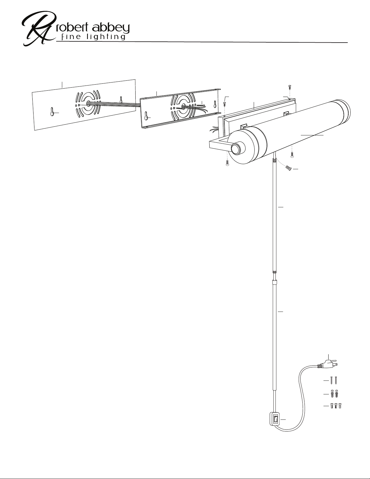
(A)
(B)
(C)
(D)
(E) (F) (G) (H)
(I)
(J)
(K)
(L)
(M)
(N)
(O)
(P)
(Q)
Page 1 of 2

WYATT 24” PICTURE LIGHT
ASSEMBLY INSTRUCTIONS FOR YOUR
250
***To clean, use soft cloth only. Do not use any chemical or abrasive cleaners.*** Page 2 of 2
13. Attach hot wire from xture (black in color or smooth side of wire) to hot wire from outlet box. Fasten wires together with wire nut (Q) and
tightly wrap connection with electrical tape.
14. Attach neutral wire from xture (white in color or ribbed side of wire) to neutral wire from outlet box. Fasten wires together with wire nut (Q)
and tightly wrap connection with electrical tape.
15. Carefully push wire connections back into wall outlet box. Slide backplate (G) over mounting plate (C).
16. Thread screws (F) into holes at the top and bottom of backplate (G) to secure the xture to the mounting surface.
17. Insert two 25W MAX. incandescent or 40W MAX. equivalent LED Type B, medium base bulbs into sockets located inside shade (I).
18. Adjust shade (I) by gently rotating it up or down.
19. Reconnect main electrical supply at the fuse box/circuit breaker and test xture.
Table of contents


