manuals.online logo
Brands
  1. Home
  2. •
  3. Brands
  4. •
  5. KSE-LIGHTS
  6. •
  7. Lighting Equipment
  8. •
  9. KSE-LIGHTS TL-EX Series User manual

KSE-LIGHTS TL-EX Series User manual

Modell
model Leistung
power (W) Eingangsspannung
input voltage Schutzklasse
protection class
Abmessungen
dimensions
(mm)
Gewicht
weight
(kg)
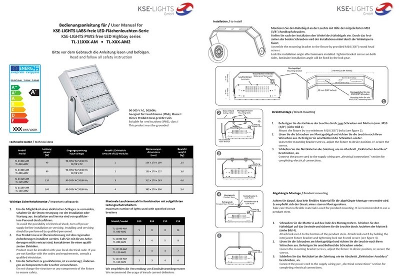
TL-EX-025-xx 25 100-240 VAC , 50/60 Hz IP66 / IK08 340 x 360 x 88 9
TL-EX-040-xx 40 100-240 VAC , 50/60 Hz IP66 / IK08 340 x 360 x 88 9
TL-EX-060-xx 60 100-240 VAC , 50/60 Hz IP66 / IK08 340 x 360 x 88 9
TL-EX-080-xx 80 100-240 VAC , 50/60 Hz IP66 / IK08 340 x 360 x 88 9
Technische Daten / technical data
Maximale Leuchtenanzahl in Kombination mit aufgeführten
Leitungsschutzschaltern
maximum number of lights used with specified circuit
breakers
Modell / model B10 B16 C10 C16
TL-EX-025 10 14 12 16
TL-EX-040 6 8 7 9
TL-EX-060 5 7 6 8
TL-EX-080 3 4 4 5
Wir empfehlen die Verwendung von Einschaltstrombegrenzern
We recommend the usage of inrush current delimiters
Wichtige Sicherheitshinweise / Important safeguards
1. Leuchte niemals in explosionsgefährdeter Umgebung öffnen
oder anschließen.
Never open or connect the light in hazardous area.
2. Um die Möglichkeit eines elektrischen Schlages zu vermeiden,
schalten Sie die Stromversorgung vor der Installation oder
Wartung aus. Installation und Service sind ausschließlich von
qualifiziertem Personal durchzuführen.
To avoid the possibility of electrical shock, turn off power
supply before installation or servicing. Installing and servicing
should be performed only by qualified personnel.
3. Das Produkt muss in Übereinstimmung mit den regionalen
Anforderungen installiert werden. Falls Sie mit diesen Anfor-
derungen nicht vertraut sind, kontaktieren Sie einen qualifi-
zierten Elektriker.
Product must be installed with your local electrical code. If you
are not familiar with the codes and requirements, consult a
qualified electrician.
4. Um die Sicherheit zu gewährleisten, ist es untersagt, Änderun-
gen an Komponenten der Leuchte vorzunehmen.
Do not change the structure or any components of the fixture
to ensure safety.
Geeignet für Feuchträume (IP66), Klasse I
Dieses Produkt muss geerdet sein
Suitable for wet locations (IP66), class I
This product must be grounded
Abmessungen / dimensions
Bedienungsanleitung für / User Manual for
EX-Flächenstrahlerserie / EX-proof flood light series
Modell / Model TL-EX-XXX
Bitte vor dem Gebrauch die Anleitung lesen und befolgen.
Read and follow all safety instruction
II 2G Ex d IIB T6 Gb
II 2D Ex tb IIIC T80°C Db
Betriebstemperatur -40°C - +50°C
Usage temperature -40°C - +50°C
Allgemeines / General
Die explosionsgeschützten Flächenstrahler der TL-EX-Serie wurden nach den Anforderungen der EN60079-0: 2009,
EN60079-1: 2007,EN60079-31:2009, IEC60079-0: 2007, IEC60079-1: 2007 sowie IEC60079-31:2008 entwickelt und
hergestellt. Die Ex-Kennzeichnung ist II2GD Ex dIIB T6 Gb,Ex tb IIIC T80°C Db, das Produkt kann somit in explo-
sionsgefährdeten Bereichen der Zone 1 und Zone 2, in denen explosive Mischungen der Gruppe IIA, IIB, T1~T6 Gase,
Dämpfe und Luft existieren, gefährdeten Bereichen der Zone 21 und Zone 22,in denen explosive Stäube auftreten
können sowie in explosionsgefährdeten Bereichen, in denen sowohl explosiver Stäube als auch oben aufgeführte Gase
auftreten, verwendet werden.
Alle beigefügten technischen Dokumente, Zeichnungen und sowie Leuchten wurden vom INERIS-Institut getestet und
zertifiziert.
Das Zertifikatkennzeichnung lautet: CE0080 INERIS 13 ATEX 0062X
Hergestellt durch TORMIN Electrical Co.,Ltd
TL-EX series LED Explosion Proof Floodlight is designed and manufactured according to requirements of EN60079-0: 2009,
EN60079-1: 2007,EN60079-31:2009, IEC60079-0: 2007, IEC60079-1: 2007 sowie IEC60079-31:2008.
The Ex marking is II2GD Ex dIIB T6 Gb,Ex tb IIIC T80°C Db and it‘s applicable for Zone 1 and Zone 2 hazardous areas that
explosive mixture of group IIA, IIB, T1~T6 gases, vapour and air may exists, Zone 21 and Zone 22 hazardous areas that
explosive dust may exist and hazardous areas that both the explosive dust and gas mentioned above exist.
All associate technical document, drawings and samples are tested and certified .
The certification of INERIS is: CE0080 INERIS 13 ATEX 0062X
Manufactured by TORMIN Electrical Co.,Ltd
Wand-, Decken-, Bodenmontage / wall, ceiling, ground mounting
1. Befestigen Sie das Gehäuse der Leuchte durch mindestens zwei Schrauben M10.
Mount the fixture by at least two M10 bolts.
2. Lösen Sie die Schrauben am Montagebügel und richten Sie die Leuchte nach Ihren Wünschen aus. Befestigen Sie anschließend die
Schrauben wieder.
Loosen the mounting bracket screws, adjust the fixture to desire position, re-secure the screws.
3. Schließen Sie das Netzkabel an die Zuleitung wie im Abschnitt „Elektrischer Anschluss“ beschrieben, an.
Connect the power cord to the supply wiring per „electrical connections“ section for completing electrical connections.
Bestandteile der flammsicheren Konstruktion
1. In den flammsicheren Verbindungen sind O-Dichtungsringe eingelassen, um die Anforderungen an die
Staubsicherheit zu erfüllen.
2. Die LEDs, optischen Linsen, Reflektoren, Schaltnetzteil sowie Anschlüsse sind innerhalb der flammsicheren Kammer
verbaut.
3. Das Gehäuse sowie die Frontabdeckung sind aus Aluminium ADC12 hergestellt. Die Anteile an Magnesium und Titan
sind kleiner als 7,5%, bei einer Aluminiumdicke von 3,5 mm.
4. Der transparente Teil wird aus gehärtetem Borosilikatglas (feuerfestem Glas) mit einer Mindeststärke von 10 mm
gefertigt.
5. Zwei Kabeleinführungen mit Klemmringverschraubungen und Dichtungsringen sind im Gehäuse angebracht.
6. Das Gehäuse kann statischen Kräften widerstehen (1,0 MPa für nicht weniger als 10 s), wie In EN60079-1 und
IEC60079-1 gefordert.
7. Die maximale Gehäusetemperatur beträgt in Normalbetrieb nicht mehr als 80°C.
Quetschdichtungen für verschiedene Kabeldurchmesser
Crimp seals for different cable diameters
Installations- und Servicewarnungen
1. Bitte überprüfen Sie die folgenden Punkte vor der Installation, das Produkt darf nicht in Betrieb genommen werden, falls einer
davon nicht erfüllt ist.
a. Prüfen Sie, ob eine Zertifikatsnummer vorhanden ist.
b. Prüfen Sie, ob der vorgesehene Installationsort den aufgeführten Bereichen der Ex-Kennzeichnung entspricht.
c. Vergewissern Sie sich, dass kein Riss oder ähnliche Beschädigungen des Gehäuses einen Einsatz im explosionsgefährdetem Bereich
unmöglich macht.
2. Die flammsicheren Kabelverbindungen sind ein wichtiger Bestandteil für die Ex-Sicherheit. Sie sollten vor äußeren
mechanischen Einflüssen geschützt sein.
3. Wählen Sie die passende Dichtungsgröße zu Ihrem Anschlusskabel aus. Das Kabel sollte einen Außendurchmesser von mindestens 9 mm
besitzen. Dichtungen für Durchmesser 9-10 mm, 11-12 mm sowie 13-14 mm sind im Lieferumfang enthalten.
4. Führen Sie das Kabel durch die Druckmutter, die Unterlegscheibe sowie die Dichtung, bis die passende Länge im Gehäuse erreicht ist.
Drehen Sie nun die Druckmutter soweit fest, bis das Kabel festgeklemmt ist.
5. Wie empfehlen zum Anschluss H07RN-F 3G1.
6. Reinigen Sie die Leuchte im Innern nach der Verdrahtung. Stellen Sie sicher, dass die Dichtungen vollständig enthalten sind.
7. Die Kabeleinführungen sind vom Typ Überwurfmutter mit Dichtring. Der Außendurchmesser des Kabels muss für den Innendurchmesser
des Dichtringes geeignet sein, der Außendurchmesser des Kabels darf nicht kleiner als der auf dem Dichtring angegebene Mindestwert
sein. Zwischen dem Dichtring und dem Gehäuse, dem Dichtring und dem Kabel dürfen nach dem Befestigen der Überwurfmutter keine
Spalten entstehen, da sonst der Ex-Schutz verloren geht. Das Material des Dichtrings ist Ethylen-Propylen-Dieneterpolymer-Kautschuk
4045.
Flame proof structural features
1. This product is of flame proof strucure, O-type sealing rings are adopted in the flame proof joints to make this
product fulfill the dust proof structural requirements.
2. LED illuminant, LED lens, reflection cup, power supply and terminals are installed in flame proof chamber.
3. The main enclosure and front cover are made of aluminium alloy ADC12 with minimum thickness of 3,5 mm.
4. The transparent part is made of toughened high borosilicate glass with minimum thickness of 10 mm.
5. Two cable entries with compression nuts and sealing rings are mounted on the main enclosure.
6. The enclosure can withstand static test (1.0 Mpa for no less than 10 seconds) specified in EN60079-1 and IEC60079-1,
no deformation or damage allowed for qualified products.
7. The maximum surface temperature of the enclosure is no more than 80°C in normal service.
Installation and service cautions
1. Check the following items before installation, the product can not be put into use if any of the followings is not satisfied:
a. Check if there is a certificate or confirmation number.
b. Check if the application area indicated in the Ex marking is suitable for the intend location.
c. Check if there is any crack or other defect that may damage the ex-performance.
2. Flame proof joint of the product is an important structure for Ex performance, it should be protected from knock, crack or
contamination. It‘s not allowed to disassembly the floodlight at will.
3. Select the appropriate seal size for your connection cable. The cable should have an outer diameter of at least 9 mm. Seals for
diameters 9-10 mm, 11-12 mm and 13-14 mm are included.
4. Remove the compression nut, gasket, sealing ring successively before wiring; then make the cable get through the compression nut,
gasket, sealing ring successively (locate the gasket and sealing ring into the cable entry). At last adjust the length of the cable and
fasten the compression nut to ensure the Ex performance.
5. We recommend H07RN-F 3G1 cable.
6. Clear the dirt and foreign matters inside the flameproof chamber and on the flame proof joint after wiring; then close the top cover
and fasten the fasteners. Make sure the spring gaskets are well installed, no missing allowed.
7. The cable entry are of compression nut type with sealing ring. The outer diameter of the cable shall be suitable for the inner diameter
of the sealing ring, the outer diameter of the cable shall no less than the minimum value indicated on the sealing ring. There shall be
no gaps between the sealing ring and the enclosure, the sealing ring and the cable after fastening the compression nut, otherwise
the Ex-performance will lost. The material of the sealing ring is ethylene-propylene-dieneterpolymer rubber 4045.
Die obige Abbildung zeigt den minimal zulässigen Kabeldurchmesser.
The Figure above shows the minimum allowable cable diameter.
Kundenservice / after sales service
Auf dieses Produkt wird eine Garantie von 3 Jahren gewährt. Die Garantiezeit beginnt mit dem Rechnungsdatum.
Die Garantie bezieht sich auf Materialfehler oder Fehlfunktionen, die nicht durch unsachgemäßen Gebrauch verursacht wurden.
Im Garantiefall den Strahler bitte mit einer Kopie der Kaufrechnung an den Händler zurückgeben. Die Strahler werden entweder
repariert oder ausgetauscht.
Die Leuchte nicht mehr benutzen, wenn Teile defekt sind oder fehlen. Für Folgeschäden, die durch defekte Teile verursacht
werden, kann keine Garantieleistung in Anspruch genommen werden. Bei Zuwiderhandlung erlöschen die Garantie und die
Betriebssicherheit.
Unter den folgenden Umständen werden die Reparaturkosten berechnet:
1. Nach Ablauf der Garantiezeit.
2. Die Serien-/LOT-Nummer fehlt oder nicht mit der Serien-/LOT-Nummer in der Leuchte übereinstimmt.
3. Die Leuchte durch unsachgemäßen Gebrauch beschädigt wurde.
4. Die Leuchte durch Fall bzw. Anstoß beschädigt wurde.
5. Bei Folgeschäden die entstehen, weil der Strahler mit defekten Teilen weiterbenutzt wurde.
The warranty of this product is valid for three years after purchasing. The time of warranty starts with the date on purchase
invoice. The warranty extends over material defects or dysfunctions that are not caused by improper use. In case of
guarantee please fill out the customer service form full and return this together with lamp and a copy of the purchase
invoice to the local distributor. The lamp will be repaired or a replacement will be issued.
Secondary damage caused by the use of the lamp with broken parts are not covered by the warranty.
In case of misuse, the warranty will be invalidated.
For the following conditions we will repair the product at appropriate charge:
1. Beyond the three-year warranty.
2. If the serial number is missing or differs from number inside the product.
3. If lamp has been damaged by improper operation.
4. If lamp has been cracked or damaged by impact.
5. Secondary damages caused by the use with broken parts (such as broken housing or switch rubber)
9. Der Anschluss und das Versorgungskabel sollten IP65-tauglich sein. Als Versorgungsleitung wird mindestens H07RN-F 3 x 1 mm² empfohlen.
The terminal box and supply cord used shall be suitable for IP65 environment. The supply cord shall be at least H07RN-F 3 x 1.0 mm².
10. Korrekte Entsorgung des Produktes:
Nur für EU-Länder:
Werfen Sie elektrische Geräte niemals in den Hausmüll. Entsprechend der EU-Anweisung 2012/19/EU bezüglich
alter elektrischer und elektronischer Geräte und ihrer Einbindung in nationale Gesetze, müssen alte elektrische
Geräte von anderem Müll getrennt und umweltfreundlich entsorgt werden, z.B. in einer Sammelstelle.
Wiederverwertung als Alternative zur Entsorgung: Altgeräte enthalten wertvolle recyclingfähige Materialien,
die einer Wiederverwertung zugeführt werden sollten und um der Umwelt bzw. der menschlichen Gesundheit
nicht durch unkontrollierte Müllbeseitigung zu schaden. Bitte entsorgen Sie Altgeräte deshalb über geeignete
Sammelsysteme oder senden Sie das Gerät zur Entsorgung an die Stelle, bei der Sie es gekauft haben. Diese wird dann das Gerät der
stofflichen Verwertung zuführen.
Proper disposal of this product
For EU countries only.
Never place any electric tools in your household refuse. To comply with European Directive 2012/19/EU
concerning old electric and electronic equipment and its implementation in national laws, old electric
tools have to be separated from other waste and disposed of in an environment-friendly fashion, e.g. by taking
to a recycling depot. Recycling alternative to the demand to return electrical devices: As an alternative to
returning the electrical device, the owner is obliged to cooperate in ensuring that the device is properly
recycled if ownership is relinquished. This can also be done by handing over the used device to a returns center,
which will dispose of it in accordance with national commercial and industrial waste management legislation. This does not apply to the
accessories and auxiliary equipment without any electrical components which are included with the used device.
Weitere Hinweise / additional advices
1. Die Leuchte nicht fallen lassen, und vor Stößen schützen.
Do not let the lamp drop and avoid impact.
2. Decken Sie die Leuchte nicht ab, hängen und befestigen Sie nichts an dem Produkt.
Do not cover the product, do not hang or fasten anything on the product.
3. Defekte Leuchten nicht mehr benutzen und an den Händler zurückgeben.
Never open the product. In case of failure, please return the lamp to seller.
4. Montagearbeiten und Arbeiten am elektronischen Anschluss darf nur eine zugelassene Elektrofachkraft durchführen.
Mounting or works on the electrical connection may only be carried out by an approved electrician.
5. Nicht direkt in die Augen von Menschen und Tieren leuchten!
Never direct the light of the lamp directly in the eyes of humans or animals!
6. Die Leuchte darf nur von autorisierten Fachkräften repariert werden. Durch unbefugtes Reparieren verliert die Leuchte ihre Garantie und
die Sicherheit kann nicht mehr gewährleistet werden.
The product may only be repaired by specialists. Being repaired without authorization, the product will lose its warranty and safety can no
longer be guaranteed.
7. Sichtbare LED Strahlung nicht direkt mit optischen Instrumenten betrachten.
Never look at visible LED radiation with optical instruments.
8. Der Anschluss sollte so gewählt werden, dass eine Verdrahtung mit 3 x 1 mm²-Kabel möglich ist.
The terminal used shall be suitable for 3 x 1 mm² wiring.
Schließen Sie die elektrischen Leitungen wie folgt an / make the following electrical connections:
1. Verbinden Sie den Schutzleiter (grün-gelb) mit dem Schutzleiter des LED-Treibers .
Connect INPUT GROUND conductor to GROUND conductor of LED driver.
2. Verbinden Sie die Eingangsphase (braun) mit der Phase des LED-Treibers.
Connect INPUT VOLTAGE conductor to LINE conductor of LED driver .
3. Verbinden Sie den Neutralleiter (blau) mit dem Neutralleiter des LED-Treibers.
Connect INPUT NEUTRAL conductor to NEUTRAL conductor.
4. Stellen Sie sicher, dass alle Leitungen sicher im Anschlussblock stecken und die Schrauben fest angezogen sind.
Make sure all excess input wires are pushed into pole, screws are tightened.
Elektrischer Anschluss / Electrical connection
Elektrischer Anschluss / Electrical connection 100-240V AC, 50/60 Hz
Kabeleinführungen für Anschlussleitung
sowie zum Durchschleifen auf nächste
Leuchte ohne zusätzlichen Anschlusskasten
Cable entries for connecting cable and for
looping through to next luminaire without
additional plenum box
Anschlussblock
Terminal block

This manual suits for next models

4

Other KSE-LIGHTS Lighting Equipment manuals

KSE-LIGHTS 6003 Series User manual

KSE-LIGHTS

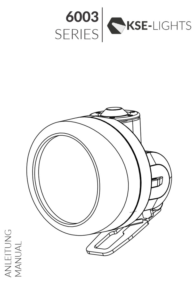
KSE-LIGHTS 6003 Series User manual

KSE-LIGHTS HERO KS-8000 User manual

KSE-LIGHTS

KSE-LIGHTS HERO KS-8000 User manual

KSE-LIGHTS TL-11 AM Series User manual

KSE-LIGHTS

KSE-LIGHTS TL-11 AM Series User manual

KSE-LIGHTS HL-1000-EX User manual

KSE-LIGHTS

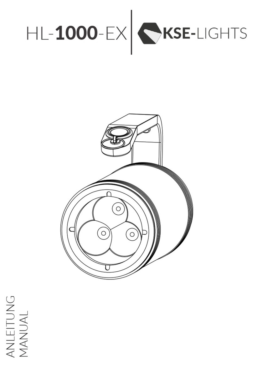
KSE-LIGHTS HL-1000-EX User manual

KSE-LIGHTS HL-3000-EX User manual

KSE-LIGHTS

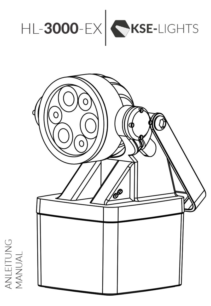
KSE-LIGHTS HL-3000-EX User manual

KSE-LIGHTS LED-MAMBA FSL-15 User manual

KSE-LIGHTS

KSE-LIGHTS LED-MAMBA FSL-15 User manual

KSE-LIGHTS KS-7650 User manual

KSE-LIGHTS

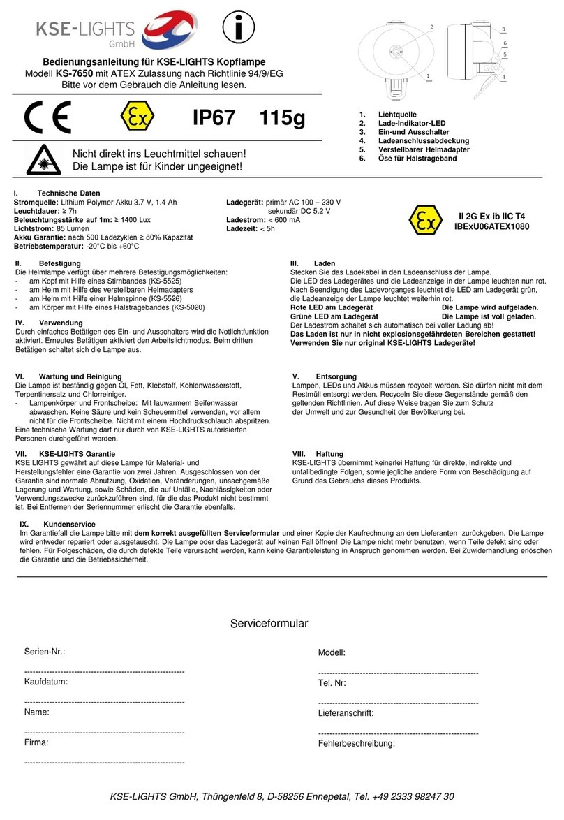
KSE-LIGHTS KS-7650 User manual

KSE-LIGHTS HL-1000-EX User manual

KSE-LIGHTS

KSE-LIGHTS HL-1000-EX User manual

Popular Lighting Equipment manuals by other brands

Eaton ephesus Arena Series installation instructions

Eaton

Eaton ephesus Arena Series installation instructions

American DJ X-Treme/AS User instructions

American DJ

American DJ X-Treme/AS User instructions

Kanlux VARSO LED SE Series manual

Kanlux

Kanlux VARSO LED SE Series manual

Forcell MFI user manual

Forcell

Forcell MFI user manual

KSR KSR98202 Installation sheet

KSR

KSR KSR98202 Installation sheet

LITETRONICS VL Series installation instructions

LITETRONICS

LITETRONICS VL Series installation instructions

Whelen Engineering Company Lightheads installation guide

Whelen Engineering Company

Whelen Engineering Company Lightheads installation guide

Pahlen Level control 11250 user manual

Pahlen

Pahlen Level control 11250 user manual

Grower's Choice TSL-800 user manual

Grower's Choice

Grower's Choice TSL-800 user manual

INSTER DHJSBM2432VCSK Series Installation and operating manual

INSTER

INSTER DHJSBM2432VCSK Series Installation and operating manual

Eterna BH60BK Safety and installation instructions

Eterna

Eterna BH60BK Safety and installation instructions

Sealey LED360CM instructions

Sealey

Sealey LED360CM instructions

Uplus Lighting 200 LED BSW user manual

Uplus Lighting

Uplus Lighting 200 LED BSW user manual

amaran 200x user manual

amaran

amaran 200x user manual

MIIDEX LIGHTING Vision-EL 779053 Notice Instructions

MIIDEX LIGHTING

MIIDEX LIGHTING Vision-EL 779053 Notice Instructions

Lightolier Lytecaster 1002 Instructions for maintenance reference

Lightolier

Lightolier Lytecaster 1002 Instructions for maintenance reference

GLG LED Moving Head Beam 7X12W Osram user manual

GLG

GLG LED Moving Head Beam 7X12W Osram user manual

Monzana DBKB001 instructions

Monzana

Monzana DBKB001 instructions

manuals.online logo
manuals.online logoBrands
  • About & Mission
  • Contact us
  • Privacy Policy
  • Terms and Conditions

Copyright 2025 Manuals.Online. All Rights Reserved.