Robert Sorby ProEdge User manual

THE ULTIMATE SHARPENING SYSTEM
INSTRUCTION MANUAL

The Robert Sorby ProEdge Sharpening System
Thank you for purchasing the Robert Sorby ProEdge sharpening system, it has been
designed using hundreds of years of tool manufacturing experience.
The simple set-up and operation of the ProEdge makes sharpening tools a pleasure and
gives the woodworker great satisfaction in achieving a perfect sharp edge every time.
EC DECLARATION OF CONFORMITY
Business Name & Address Of Responsible Person:
- Robert Sorby, Athol Road, Sheeld, S8 OPA England.
Capacity /Role of Responsible Person:
- Manufacturer
Description of Machine:
- ProEdge Sharpening System
Serial Number:
- Axed to machine and box lid
Relevant EC Directives & Regulations Complied with for Above Machine:
- Supply of Machinery (Safety) Regulations 1992 - Amended 1994: Machinery Directive 98/37 /EEC
Relevant EC Transposed Harmonised Standards
- BS.EN 1050; BS.EN 292; (ISO14121); BS.EN 953;
National Standards Used:
- BS.EN 5304 - Safety of Machinery
DECLARATION:
I certify that on completion of manufacture of the machine detailed above that a full conformity
assessment has been completed and relevant essential health & safety requirements complied with:
Name: Ian Finkill
Status within Company: General Manager
Signature:
2

3
WARNING
THESE INSTRUCTIONS MUST BE READ AND UNDERSTOOD
BEFORE OPERATING THE MACHINE
GROUNDING INSTRUCTIONS
All grounded, cord-connected tools:
In the event of a malfunction or breakdown, grounding provides a path of least resistance
for electric current to reduce the risk of electric shock. This tool is equipped with an electric
cord having an equipment grounding conductor and a grounding plug. The plug must
be plugged into matching outlet that is properly installed and grounded in accordance
with all local codes and ordinances. Do not modify the plug provided - if it will not t the
outlet, have the proper outlet installed by a qualied electrician. Improper connection of
the equipment-grounding conductor can result in a risk of electric shock. The conductor
with insulation having an outer surface that is green with or without yellow stripes is the
equipment-grounding conductor. If repair or replacement of the electric cord or plug is
necessary, do not connect the equipment grounding conductor to a live terminal.
Check with a qualied electrician or service personnel if the grounding instructions are not
completely understood, or if in doubt as to whether the tool is properly grounded.
Use only 3-wire extension cords that have 3-prong grounding plugs and 3-pole receptacles
that accept the tool’s plug. Repair or replace damaged or worn cord immediately.

4
WARNING
• RISKOFINJURYDUETOACCIDENTALSTARTING-Do not use in an area where children may
be present
• KEEPGUARDSINPLACEand in working order
•REMOVEADJUSTINGKEYSANDWRENCHES.Form habit of checking to see that keys and
wrenches are removed from tool before turning it on
• KEEPWORKAREACLEAN.Cluttered areas and benches invite accidents
• DON’TUSEINDANGEROUSENVIRONMENT.Don’t use power tools in damp or wet locations,
or expose them to rain. Keep work area well lit
• KEEPCHILDRENAWAY.All visitors should be kept a safe distance from work area
• MAKEWORKSHOPCHILDPROOFwith padlocks, master switches, or by removing starter
keys
• DON’TFORCETOOL.It will do the job better and safer at the rate for which it was designed
•USERIGHTTOOL.Don’t force tool or attachment to do a job for which it was not designed
• USEPROPEREXTENSIONCORD. Make sure your extension cord is in good condition. When
using an extension cord, be sure to use one heavy enough to carry the current your product
will draw. An undersized cord will cause a drop in line voltage resulting in loss of power and
overheating
*Table 1 shows the correct size to use depending on cord length and nameplate ampere rating. If in doubt,
use the next heavier gauge. The smaller the gauge number the heavier the cord.
WEARPROPERAPPAREL. Do not wear loose clothing, necktie’s, rings, bracelets, or other jewellery which
may get caught in moving parts. Non-slip footwear is recommended. Wear protective hair covering to
contain hair.
ALWAYSUSESAFETYGLASSES. Also use face or dust mask if cutting operation is dusty. Everyday
eyeglasses only have impact resistant lenses, they are NOT safety glasses.
Table 1 - Minimum gauge forcord
Amphere Rating
More Than Not More Than
Volts Total length of cord in feet
AWG
Not Recommended
120 V
240 V
25 ft.
50 ft.
50 ft.
100 ft.
100 ft.
200 ft.
150 ft.
300 ft.
0
6
10
12
6
10
12
16
18
18
16
14
16
16
16
12
16
14
14
14
12
12

5
WARNING
• SECUREWORK.Use clamps or a vice to hold work when practical. It’s safer than using
your hand and it frees both hands to operate tool
• DON’TOVERREACH.Keep proper footing and balance at all times
• MAINTAINTOOLSWITHCARE.Keep tools sharp and clean for best and safest
performance. Follow instructions for lubricating and changing accessories
• DISCONNECTTOOLSbefore servicing: when changing accessories and belts
• REDUCETHERISKOFUNINTENTIONALSTARTING.Make sure switch is in o
position before plugging in
• USERECOMMENDEDACCESSORIES.Consult the owner’s manual for recommended
accessories. The use of improper accessories may cause risk of injury to persons
• NEVERSTANDONTOOL.Serious injury could occur if tipped or if the cutting tool is
unintentionally contacted
• CHECKDAMAGEDPARTS.Before further use of the tool, a guard or other part that is
damaged should be carefully checked to determine that it will operate properly and
perform its intended function - check for alignment of moving parts, binding of moving
parts, breakage of parts, mounting, and any other conditions that may aect its
operation. A guard or other art that is damaged should be properly repaired or replaced
• DIRECTIONOFFEED.Feed work into a blade or cutter against the direction of rotation
of the blade or cutter only
• NEVERLEAVETOOLRUNNINGUNATTENDED.TURNPOWEROFF.Don’t leave tool
until it comes to a complete stop

6
RESIDUAL HAZARDS
1.Frictionandabrasionarisingfromcontactwiththebeltsurfaceatthepointwhereitis
exposedforuse.
Precaution - no further enclosure is deemed to be practicable and therefore the appropriate
guides should be used when completing the sharpening operation and, furthermore, care
should be exercised by adopting safe working practice.
2.Trappointin-betweenthebeltandpulley.
Precaution - x side guard in position on delivery. This must always be replaced prior to use
whenever belts are changed.
During the belt changing operation, the machine should be disconnected from the electrical
supply with full isolation being retained until the guard is axed.
The moulded plastic retaining nuts must always be replaced prior to usage.
3.Machinesmovingortopplingoverduringusage.
Precaution - secure the machine to the workbench utilising the four holes in the base plate.
4.Ejectionhazards.Smallparticlesmaybeejectedfromthebeltandthetoolduringthe
sharpeningoperationorintheunlikelyeventofthebeltbreakingduringusage.
Precaution - wear suitable approved eye protection during usage.
5.Entanglementwithbungandpolishingattachments.Precaution-removejewelleryand
watchesandavoidlooseclothing.
6.Inhalationofdustarisingfromtheabrasivecoatingonthebeltandthetoolbeingsharpened.
Precautions - the normal usage of the ProEdge is such that it is highly unlikely that the dust
hazard would become a health risk. Not withstanding this, repeated and consistent use may
lead to signicant volumes of dust arising and it is therefore recommended that for high levels
of usage, the machines should be connected to an appropriate local exhaust ventilation system
(LEV) via the port at the bottom of the existing enclosure guard. Should the machine not be
tted to LEV, an appropriate cover plate should be tted over the aperture. Suitable EC
approved (or equivalent) respiratory protection (dust mask) should be worn when grinding
tools.
7.Manualhandling-eachProEdgeweighsapproximately31lbs(14kg).
Precaution-Careshouldbeexercisedwhenlifting.

7
Angle setter
Angle selection pin
ASharpening belt
release lever
Belt tension spring
Belt tracking spindle
shaft and collar
B
Technical Details
Motor:1/2hpBeltWidth:2”BeltSpeed1400ft(440m)perminutetoachievethebestresultsfrom
yoursystem,pleasefamiliariseyourselfwithallofitspartsandaccessories.
Accessory
attachment hub
(Drive pulley)
Platform locking lever
On/O switch
Angle setter
information guide
Fingernail boss bar
Large tool platform
Jig location slot
Abrasive sharpening belt
Belt
assembly
swivel
screws
A
B
C
C
8
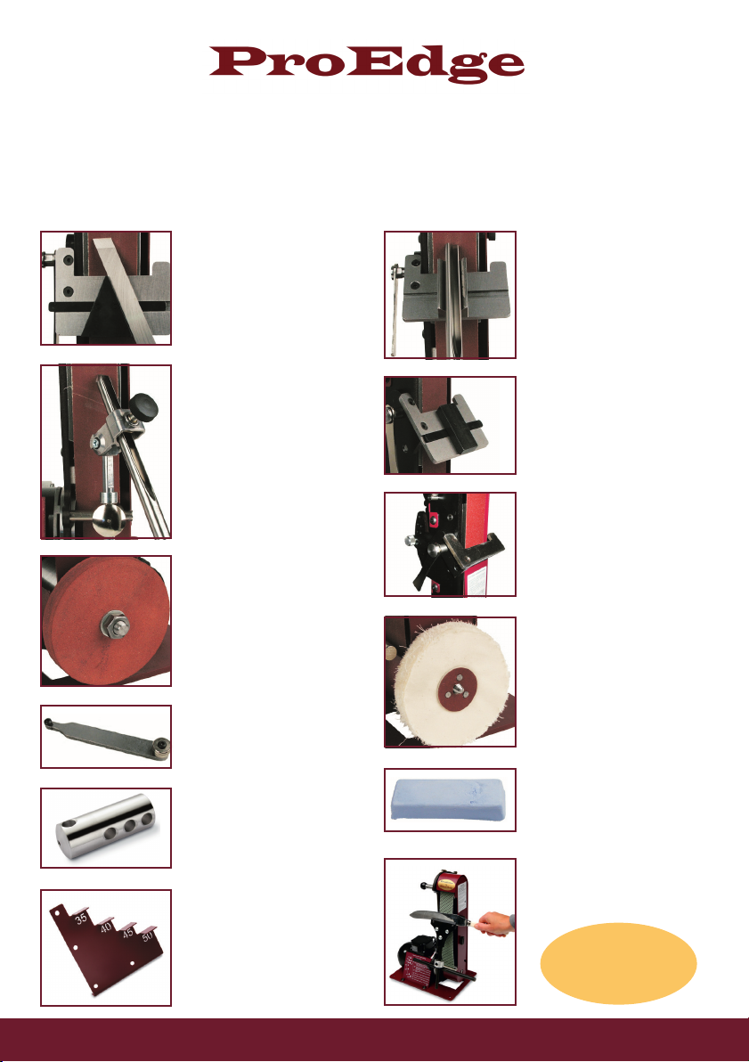
Accessories
A full list of all the accessories and sharpening belts is on the back page of this booklet. All the accessories
are available from Robert Sorby dealers. Those marked* are included in the ProEdge Plus.
Skew Chisel Jig*
Create the perfect bevel and
cutting edge on any skew chisel
Fingernail Prole Arm*
Maintain the desired ngernail
prole on any spindle & bowl
gouge from 1/4” (6mm) -
3/4” (19mm)
Honing Wheel & Arbor
Fixed to the accessory
attachment hub using the arbor.
The rubberised honing wheel can
be shaped to suit any tool
Cutter Holder
A multitude of cutters can be
sharpened by using this cutter
holder
Long Grind Jig
Allows 3 dierent types of prole
on bowl and spindle gouges-
ngernail, long and extra long
ProSet
Enables exact bevel angles
to be set
Standard Prole Gouge Jig*
Any standard prole gouge can
be sharpened quickly and easily
using this v-block skew chisel
Woodworking Chisel Jig
A simple way to achieve any
primary and secondary bevel
angles on all woodworking
chisels and plane irons
Short Tool Platform
This tool platform allows
tools with short blades to be
sharpened
Bung Mop & Pigtail Mandrel
Screwed onto the pigtail
mandrel, the loose leaf cotton
mop will produce a highly
polished nish on any tool when
used in conjunction with the
honing paste
Honing Paste
Used in conjunction with the
bung mop the honing paste
produces a very high polish on
any too
Knife Sharpening Jig
for sharpening carving, hunting,
pocket and kitchen knives
Full details of the sharpening
belts available on
page 12
Belts!

9
Preparingforuse
Sharpening Belt Alignment
Place the front edge of the base plate so that it is level with the leading edge of the worktop or
bench. Screw or bolt the base plate in this position.
Ensure the on/o switch is in the OFF position and plug into a standard electric wall socket. Check
the cable is in a safe position and that all moving parts of the machine are clear of any obstruction.
Switch on the power at the wall socket and switch the system on. Before operating the machine
please watch the belt to check for alignment, it has been pre-tracked in the factory but it may have
moved during transit.
Those marked* are included in the ProEdge Plus.
HowtoadjusttheBeltAlignment
While the system is running, place the two tracking adjustment bars into the holes in the spindle shaft
and the locking collar. Holdtheshaftstationaryandslackenthelockingcollar(anti-clockwise)
priortomovingthetrackingshaft. Small adjustments of the tracking shaft will move the belt to the
left and right on the pulley.
Please ensure the belt is tracked to the right hand edge of the backplate.

Tilting the Sharpening Belt Assembly
To assist in sharpening tools the ProEdge has a very useful feature in that the sharpening
belt assembly can be angled backwards to allow for a much more comfortable position when
sharpening at shallow angles.
- This is done by loosening the two screws by a quarter of a turn, next to the drive pulley and gently
moving the belt assembly to your desired angle
- When the belt assembly is tilted backwards the rear screw is accessed via the access slot in the
side guard as shown below
- When the desired angle is achieved, re-tighten the screws (nger tight) to secure the belt assembly
in place
Front screw
just below the
ngernail boss
bar - 1/4 of a
turn
Rear screw
- 1/4 of a turn
Access
slot
10
This manual suits for next models
20
Table of contents
Other Robert Sorby Tools manuals


