ROBOTIQ EPick User manual

Robotiq EPickVacuumGripper
forTM Robots
InstructionManual robotiq.com | leanrobotics.org
Original Notice
© 2019Robotiq Inc.

Revisions 5
1. General Presentation 7
1.1. Grippernomenclature 7
1.1.1. EPick Gripper 7
1.1.2. Suction Cup System 8
1.2. Object picking 9
1.2.1. Main unit suction cup 9
1.2.2. Auxiliarysystem with multiple suction cups 9
1.3. Setup and control 9
2. Safety 11
2.1. Warning 12
2.1.1. Risk assessment and final application: 12
2.2. IntendedUse 13
3. Installation 14
3.1. Scopeof Delivery 14
3.1.1. Robotiq EPick Vacuum Gripper Kit 14
3.2. RequiredToolsand Equipment 16
3.2.1. EPick Gripper Add-On 16
3.2.2. Suction cup system 16
3.3. EnvironmentalandOperatingConditions 16
3.4. MechanicalInstallation 17
3.4.1. Installing the Vacuum Gripper onto the robot 17
SingleGripper 17
3.4.2. Air tubing 18
Connection of thesuction cup systems 18
3.4.3. Suction cup system 19
Manifold and mounting bracket 19
Suction cupsand airnodes 20
3.5. ElectricalSetup 21
3.5.1. Pinout interface 21
3.5.2. Coupling to controller 22
Single Vacuum Gripper 23
3.6. Testing the Gripperwiththe Robotiq UserInterface (RUI) 24
EPick- InstructionManual
2

3.6.1. License Agreement 26
4. Software 29
4.1. Overview 29
4.1.1. Control using registers 29
4.2. VacuumGripperregistermapping 31
4.3. Robot output registers& functionalities 31
4.4. Robot input registers& status 35
4.5. Gripperbehavior 38
4.5.1. Control modes 38
Automaticmode 38
Advanced mode 39
Veryporousmaterial detection 41
Object lost/ drop behavior 41
Object secured behavior 41
Object not detected behavior 42
Object releasedelay 42
Emergencystop behavior 42
4.6. Controllogic 42
4.7. ModbusRTUcommunication 42
4.7.1. Connection setup 43
4.8. ControloverTM 44
4.8.1. TM Robotscompatibilitywith Robotiq Vacuum Grippers 44
4.8.2. Getting Started 44
4.8.3. TM Vacuum Gripper Components 48
Installation 48
Gripper Button 53
Programming 56
Advanced Mode 57
GRIPComponent 58
RELEASEComponent 58
SelectID Component 59
Changing theModbusSlave ID 59
5. UserInterface 62
3

EPick- InstructionManual
6. Specifications 63
6.1. Technicaldimensions 64
6.1.1. Gripper 64
6.1.2. Suction Cup System 65
Manifold 65
Bracket for 2suctioncups 65
Bracket for 4suctioncups 66
6.1.3. Air nodes 68
6.1.4. Couplings 69
Blankcoupling 69
Coupling forISO 9409-1-50-4-M6 70
6.2. Mechanicalspecifications 71
6.2.1. Payload and force 72
Example1:Non-porousmaterial 75
Case#2 76
Example2:Porousmaterial 76
Case#1 78
6.2.2. Center of massand tool center point 79
6.2.3. Moment Limitation 80
6.3. Electricalspecifications 80
7. Maintenance 81
7.1. VacuumGrippercleaning 82
7.2. Periodicinspection 83
Suction cupsand airnodes 84
8. Spare Parts, Kitsand Accessories 85
9. Troubleshooting 88
9.1. VacuumGripperverification 88
10. Warranty 89
11. Harmonized Standards, Declarationsand Certificates 91
11.1. OriginalECdeclarationof incorporation 91
11.2. Appliedstandards 92
12. Contact 93
4

Revisions
Robotiq maymodifythisproduct without notice,whennecessary,dueto product improvements,modificationsorchangesin
specifications.If suchmodification ismade,themanual will also berevised,seerevision information.See thelatest versionof this
manual online at support.robotiq.com.
2019/08/13
lUpdateof thelatest TMflow1.72.3500
lUpdateof theversionV_002of thecomponents
2019/07/02
Initial release
5

EPick- InstructionManual
Copyright
© 2019 Robotiq Inc.All rightsreserved.
Thismanual and theproduct it describesareprotected bytheCopyright Act of Canada,bylawsof othercountries,and byinternational
treaties,and thereforemaynot be reproduced inwhole orinpart, whetherfor sale or not,without prior writtenconsent from Robotiq.
Undercopyright law,copying includestranslationinto anotherlanguageorformat.
Informationprovided byRobotiq inthisdocument isbelieved to beaccurateand reliable.However,no responsibilityisassumed by
Robotiq foritsuse.Theremaybesomedifferencesbetweenthemanual and theproduct if theproduct hasbeenmodified afterthe
edition date.
Theinformationcontained inthisdocument issubject to changewithout notice.
6

1.General Presentation
The terms“ Gripper”,"EPickGripper","EPickVacuum Gripper" and "EPick" used in the following manual all refer to theRobotiq EPick
Vacuum Gripper.The Robotiq EPick Vacuum Gripper isa roboticperipheral designed for industrial applications. The vacuum is
generated withanelectricvacuum pump. Itsdesign makesit a unique roboticend-of-arm tool to quicklypick,place and handle alarge
rangeof partsof varying sizesand shapes.
Info
Thefollowing sectionpresentsthe keyfeaturesof the Gripperand must not beconsidered asappropriateto theoperationof
theGripper.Eachfeature isdetailed in theappropriate section.
Info
The following manual usesthemetricsystem.Unlessspecified,alldimensionsare inmillimeters.
1.1.Grippernomenclature
1.1.1.EPickGripper
The EPickGripperisa vacuum Gripperthat generates avacuum with an electricvacuum pump..It isequipped with one or multiple
suctioncups.Eachsuctioncup canbeadapted to your application and grasping needs.TheEPickGripperiscompatible withthe
Robotiq standard coupling interface.
Fig.1-1:Robotiq EPickGripper
EPick- InstructionManual
7

Info
Please referto the ScopeofDeliverysection subsectionand theSpare Parts,Kitsand Accessoriessectionfordetailson
standard and optional parts.
1.1.2.SuctionCupSystem
A Robotiq Suction Cup System can be installed directly under the Vacuum Gripper. Each Robotiq Suction Cup System includes a
bracket,a manifold,air nodes,port plugs,bumpers,tubing and additional suction cups.
Fig.1-2:Suctioncup system
Info
Please referto the Installationsection formore informationonhowto integrate the SuctionCup System to EPick.
Info
Please referto the ScopeofDeliverysection subsectionand theSpare Parts,Kitsand Accessoriessectionfordetailson
standard and optional parts.
Tip
Theownercanuse acustom bracket oramounting plate.Thebracket ormounting platecanbeinstalled directlyunder the
manifold.
8

EPick- InstructionManual
1.2.Object picking
TheEPickGripperallows:
1. Mainunit suction cup
2. Auxiliarysystem with multiple suction cups
Warning
Object picking causesthecompressionof thesuctioncup(s),whichcanresult inpinching pointsbetweenthegripperand the
load.Avoid presenceof bodypartsinthiszoneduring operation.
Warning
Beforepicking anynewobject or material inautonomousmode,always checkthat the resulting vacuum level issufficient to
ensuresafe gripping,inorderto prevent dropping orejection of theload.
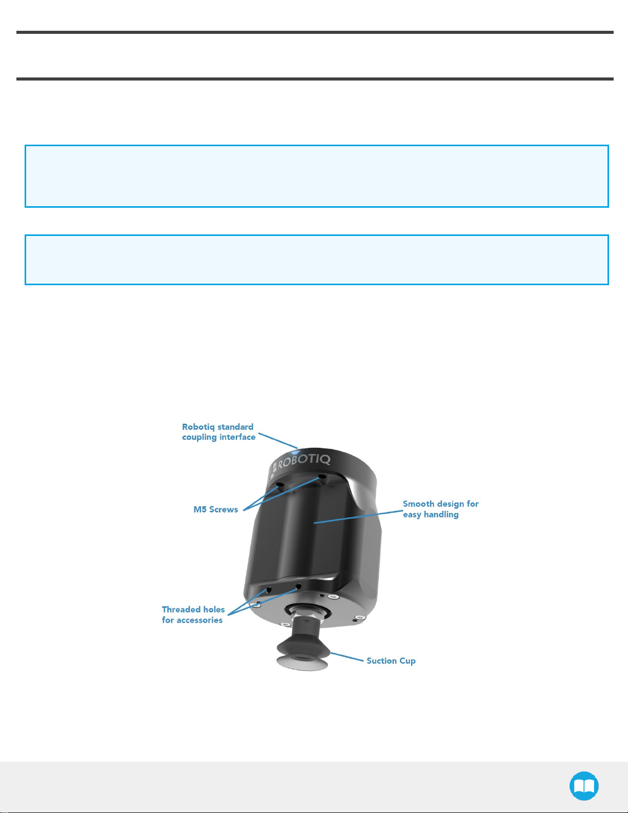
1.2.1.Main unit suctioncup
In order to use onlyonesuction cup,the single cup canbe mounted right intheport of thevacuum generator.
1.2.2.Auxiliarysystemwithmultiple suctioncups
A standard Suction Cup System can be attached to theEPick Vacuum Gripper.Thebracket normallyholdstwo or four suction cups
(corresponding to thefourportsof themanifold).
Anyunused manifold port should beblocked withamating plug to avoid airleakage.
Other custom mounting optionscanalso be used to benefit from a multiple suction cups solution
Caution
Custom brackets and platesmust meet the required technical specifications(refer to theTechnicaldimensionssection
subsection).
1.3.Setup and control
TheVacuum Gripperispowered and controlled directlyvia asingle devicecablethat carries24VDCpowerand ModbusRTU
communicationoverRS-485.
Info
Please referto the ElectricalSetup sectionsubsectionfor wiring information,and to theSoftware section for thecontrol of the
Vacuum Gripper.
Inorderto beused,theEPickGripperhasto beconnected to aGrippercoupling whichprovidesboththemechanicaland electrical
connectivityto the Gripper.
9

Info
Please referto the MechanicalInstallationsection for moreinformation on mounting theVacuum Gripperonto the coupling.
Refer to theTechnicaldimensionssection for thetechnical drawing,and refer to the Spare Parts,Kitsand Accessoriessection
foralist of theavailablecouplings.
The EPickGripperboastsanembedded object detection featurewhich usesindirect sensing measurements.The system thusindicates
if theworkpiecehasbeendropped orif theGripperfailed to grasp the workpiece.
Info
Formore informationregarding theobject detection feature,please referto theSoftwaresection.
10

2.Safety
Warning
The operatormust have read and understood all of theinstructionsinthefollowing manual beforeoperating theRobotiq
Vacuum Gripper.
Caution
The term “ operator” refers to anyoneresponsible for anyof the following operationson the Robotiq Vacuum Gripper:
lInstallation
lControl
lMaintenance
lInspection
lCalibration
lProgramming
lDecommissioning
Thismanual coversthe variouscomponents of theRobotiq Vacuum Gripper and thegeneral operationsregarding thewhole life-cycle
of the product,from installation to operation and decommissioning.
The drawingsand photosin thismanual are representativeexamples.However,discrepanciesmaybe observed betweenthevisual
supportsand the actual product.
EPick- InstructionManual
11

2.1.Warning
Caution
Anyuse of theGripperinnon-compliance withthese warningsisdeemed inappropriateand maycause injuryor damage.
Warning
lAlways use thesuction cup system and its components(air nodes,port plug,etc.)with theRobotiq Vacuum Gripper only.
lNever operate theVacuum Gripper with leaking or wornparts.
lThe Vacuum Gripperneedsto be properly secured beforeoperating therobot.
lDo not install oroperateaGripperthat isdamaged or lacking parts.
lNeversupplytheGripperwith analternating current source.
lMake sureall cord setsarealwayssecured at both ends—Gripperand robot.
lAlwaysmeet therecommended keying for electrical connections.
lMakesure no individualsorassetsareinthevicinityof the robot and/orGripperpriorto initializing therobot.
lAlwaysmeet the Gripper’spayload specifications.
lSet your vacuum level based on yourapplication.
lKeep body partsand clothing awayfrom theGripperwhilethedevice ispowered on.
lDo not usetheGripperonpeople or animals.
lNever stand undersuspended loadsheld bythe Vacuum Gripper.
2.1.1.Risk assessment and finalapplication:
The Robotiq Vacuum Gripper ismeant to be used on cobotsand industrial robots.
The robot,the Gripperand anyotherequipment used in thefinal applicationmust go through acomprehensiveriskassessment
processbefore theycanbe used.Special care must be takenduring thisstep if custom mounting optionsare used for the suction cups.
Caution
It istherobot integrator’sresponsibilityto ensurethat all local safetymeasuresand regulationsaremet.
Thefollowing non-exhaustivelist presentsrisksthat must beassessed during theintegrationprocess:
lRiskof contact betweenbodypartsand suction cupsduring gripping;
lRiskof load ejection resulting from lossof vacuum;
lRiskof load dropping resulting from lossof vacuum;
12

EPick- InstructionManual
lRiskof pinching between the Vacuum Gripper and thepart(s)or theenvironment;
lRiskof damage or breaking if using a custom suction cup bracket that doesnot meet the technical requirements.
Depending on theapplication,theremaybe hazardsthat require additional protectionand/orsafetymeasures.For instance,the
workpiecehandled bytheGrippercould beinherentlydangerousto theoperator.
Warning
Depending onthesupplysources,whenanemergencystop (e-Stop)buttonispressed,thefollowing consequencesmay
occur.Therobot ownerhastheresponsibilityto do a riskassessment and choosetheappropriateoption.
Supplysources e-Stop consequences
Robot tool supply
(tool connector)
Powerfailureto the Vacuum Gripper.The vacuum level will drop to ambient pressureand the
object will be lost.
Robot controllersupply
(Any24Vpin)
Vacuum Gripper powered ON.
lIf anobject isdetected:thevacuum level will continueto be regulated and theobject will
not be lost.
lIf no object isdetected:the Vacuum Gripperwill go into a standbystate2secondsafter
thee-Stop buttonispressed.
Warning
Lossof vacuum canoccurdueto power failure.
2.2.Intended Use
TheGripper unit isdesigned forgripping and temporarilysecuring orholding objects.
Caution
The Gripperis NOT intended for applying force against objectsor surfaces.
Theproduct isintended forinstallationonarobot orotherautomated machineryand equipment.
Info
Alwayscomplywithlocal,state,provinceand/orfederal laws,regulation and directivesregarding automation safetyand
general machine safety.
Theunit should be used exclusivelywithinthe rangeof itstechnicaldata.Anyotheruse of theproduct isdeemed improperand
unintended.Robotiq will not be liable for anydamagesresulting from anyimproperor unintended use.
13

3.Installation
The following subsectionswill guide you through the installation and general setup of yourRobotiq Vacuum Gripper.
Warning
Beforeinstalling:
lRead and understand thesafety instructionsrelated to theVacuum Gripper.
lVerifyyourpackage according to thescopeof deliveryand yourorder.
lMakesure to have the required parts,equipment and toolslisted in Scope of delivery.
Warning
Wheninstalling:
lMeet therecommended environmental conditions.
lDo not operate theVacuum Gripper,or eventurn on thepowersupply,beforethedevice isfirmlyanchored and the machine
areaiscleared.Make surethat the airsupplyissecured.
3.1.Scope of Delivery
3.1.1.RobotiqEPick Vacuum GripperKit
Standard upondelivery:
lStandard Kit
oOne(1)electrical vacuum generator
oTwo (2)standard suction cups(two different sizes)
oOne(1)End effectorcoupling kit
oOne(1)USBstick
oOne(1)USBto RS485signal converter
oOne(1)RS485to RS232Converter
oOne(1)10-meterscommunication cable
oRequired hardware
EPick- InstructionManual
14

l2SuctionCupsKit
oOne(1)Vacuum generator
oOne(1)suction cup system for 2suction cups (1manifold, 1bracket,tubing,2 air nodes,4 suction cups)
oFour(4)standard suctioncups(two different sizes)
oFour(4)port plugs(two alreadymounted onthesuctioncup system)
oOne(1)End effectorcoupling kit
o10-metercommunication cable
oOne(1)USBto RS485signal converter
oOne(1)RS485to RS232Converter
oRequired hardware
l4SuctionCupsKit
oOne(1)Vacuum generator
oOne(1)suction cup system for 4suction cups (1manifold, 1bracket,tubing,4 air nodes,8 suction cups)
oEight (8)standard suctioncups(two different sizes)
oFour(4)port plugs
oOne(1)End effectorcoupling kit
o10-metercommunication cable
oOne(1)USBto RS485signal converter
oOne(1)RS485to RS232Converter
oRequired hardware
Info
Please referto the Spare Parts,Kitsand Accessoriessectionforalist of availablecouplings.
Caution
Thefollowing are not included inthestandard delivery:
lOptionssuch as custom suction cup brackets/plates or couplingsfor mounting on variousindustrial robots.
lHardwarerequired for accessoriesorfixtures,unlessspecified.
Info
Whenpurchased asa kit,theEPick Vacuum Gripperwill come ina package with the appropriatecoupling,suction cupsand
cabling.
15

EPick- InstructionManual
Please referto the Spare Parts,Kitsand Accessoriessection for additional components.
3.2.Required Toolsand Equipment
3.2.1.EPick GripperAdd-On
The following toolsare required to install the Vacuum Gripper:
lHexkeyto mount thecoupling onto therobot,according to yourcoupling
l4 mm hex keyto mount the Vacuum Gripperonto itscoupling .
3.2.2.Suctioncupsystem
The following tool isrequired to install theSuction cup system on theVacuum Gripper:
l4 mm hex keyto assemble together the suction cup system and thevacuum generator.
3.3.Environmental and OperatingConditions
CONDITION VALUE
Minimum storage/transit
temperature -30°C[-22°F]
Maximum storage/transit
temperature 60°C[140°F]
Minimum operating temperature 5°C[41°F]
Maximum operating temperature 40°C [104°F]
Humidity(non-condensing) 20-80%RH
IPRating IP4X
Table 3-1:Environmental and operating conditionsof the EPick Vacuum Gripper
Caution
Useof theVacuum Gripperisnot recommended in presence of chemicalsintheenvironment.
16

Info
Theinput filterpreventsanydust largerthan200µmfrom getting insidethepump.Drydust will prevent the accumulationon
filtersorinsidethepump.Theuseof suction cupswithintegrated filtercanbeused to reducedust accumulation.
Theexhaust must not beblocked.
3.4.Mechanical Installation
3.4.1.InstallingtheVacuumGripperontotherobot
Single Gripper
Forpurposesof powerand communication,acoupling must be used to attachtheVacuum Gripperto therobot.
Herearethestepsto followto mount theGripper on the robot arm(exploded viewinfigurebelow).Pleasenotethat all screwsshould
be secured using medium strengththreadlockers.
1. Mount thecoupling ontherobot wrist using theprovided M6screwsand tooth lockwashers.Alignproperlywiththedowel pin.
Thedowel pinismeant to have atight fit ontherobot sideand a slip fit on the effectorsideof theassembly.
2. FastentheGripperto thecoupling using theprovided M5screwsand toothlockwashers.
3. Plug thedevicecableinto thegripper'spigtail and attach the cablealong therobot armusing acablerouting system.
17

EPick- InstructionManual
Fig.3-1:Installing the Vacuum Gripper onto the robot wrist
3.4.2.Airtubing
Connection of the suction cup systems
To ensure vacuum distribution to the suction cups,connect the appropriate manifold ports with thepertaining airnodesusing the
provided plastictubing.
Info
To facilitatetheassemblyof theRobotiq Wrist Cameraonthesuctioncup system,makesureto placethetubing asshown in
thefigure to be assured that therewill be no interference withthecamera'sfield of viewwhilepreventing excessive tube
bending.
18

Fig.3-2:Airtubesalignment
3.4.3.Suctioncup system
Manifold and mounting bracket
Inorderto usethetwo (2)or the four(4)SuctionCupsSystem,assemblethevacuum generatorto the suction cup system,asshownin
thefigurebelow,using four(4)M5socket head cap screwsand four(4)M5toothlockwashers.
19

EPick- InstructionManual
Fig.3-3:Mounting example of thefoursuction cupsassemblyon the vacuum generator
Warning
Anyunused manifold port should becovered withaprovided port plug to avoid airleakage.Formore details,pleasereferto
theManifold section
Suction cupsand air nodes
Whetheryouareusing astandard orcustom option,air nodesshould beused to connect thesuction cupsand theairtubing,and to
prevent airleakageasmuchaspossible.Airnodesareeasyto assemble,asshowninthefiguresbelow.
1. Screwbyhand each provided vacuum cup to anair bolt.
Fig.3-4:Screwing a vacuum cup and an air bolt
2. Passeachair bolt throughthemounting bracket,adjust the position of thenodealong thebracket side,alignwithmating airnuts
and tighten nodebyhand.
20
Other manuals for EPick
6
Table of contents
Other ROBOTIQ Industrial Equipment manuals
Popular Industrial Equipment manuals by other brands

Eaton
Eaton Airflex WCB Series Installation, operation and maintenance

Trumpf
Trumpf TruTool TPC 165 (2A1) manual

ThyssenKrupp
ThyssenKrupp Drive DAB530 operating manual

Tarana
Tarana 1101-1027-KT installation guide

ITALVIBRAS GIORGIO SILINGARDI
ITALVIBRAS GIORGIO SILINGARDI E Series Technical handbook

ABB
ABB HT601539 Operation manual