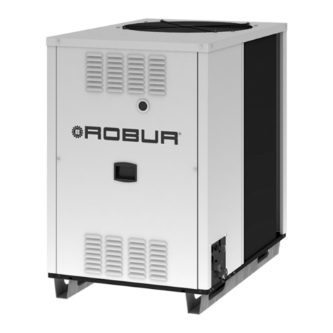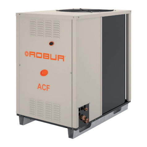
Features and technical data
Installation, use and maintenance manual – Link 7
1
1 FEATURES ANDTECHNICAL DATA
For the characteristics of the individual GAHP/GA/
AY modules that make up the Link, and of the con-
trol devices, please refer to their respective man-
uals.
1.1 FEATURES
1.1.1 Link
The Link are gas-red (natural gas or LPG) heating/cooling
groups, to supply hot and/or chilled water. Each Link con-
sists of a number of individual gas-red heating/cooling
modules (GAHP/GA/AY modules). The set of appliances
and components is preassembled at the factory, forming
a complete hydronic group already prepared to be con-
nected to the system.
1.1.2 Application
Each Link, according to its conguration (Link condens-
ing boilers, heat pumps, chillers, chiller-heaters) is able
to simultaneously or alternatively provide space heating,
cooling, DHW production and heat recovery, according to
the needs of each individual installation, with a consider-
able extension of heating and cooling output.The various
hydronic models are suitable for all heating and cooling
systems operating with hot and/or chilled water, with
common terminals (e.g. radiators, fan coils, radiant panels,
fan heaters, air handling units, DHW buer tanks, swim-
ming pool heat exchangers, ...), including process systems
(industrial heat exchangers).
1.1.3 Manufacturing features
Each Link, in addition to the GAHP/GA/AY gas-red heat-
ing/cooling modules, consists of:
▶
delivery/return stainless steel hydraulic manifolds, in-
sulated with rigid cups lined with aluminum sheet
▶
galvanized steel gas outlet manifold
▶
exible couplings of individual modules to hydraulic
and gas manifolds
▶
condensate drain manifold (only if there are at least
two condensing appliances GAHP A/GAHP GS/WS/AY)
▶
electrical panel with protection devices (2 electrical
panels with more than 6 modules)
▶
bearing structure with galvanized steel sections
1.1.4 Composition (GAHP/GA/AY modules)
The gas heating/cooling modules that make up a Link can
be:
▶
GAHP units, versions A/AR/GS/WS, gas absorption
heat pumps
▶
GA units, versions ACF/HR/TK/HT/LB, gas absorption
chillers
▶
AY units, versions AY 35/AY 50/AY 100, condensing
boilers
distinguished in:
▶
aerothermal units (A, AR, ACF, HR, TK, HT, LB)
▶
hydrothermal (WS) and geothermal (GS) units
in variable number:
▶
from 2 to 5 in the case of GAHP/GA only
▶
from 2 to 7 in the case of GAHP/GA and AY
The Link with aerothermal units must be installed exclu-
sively outdoors, while others may be installed either out-
doors or indoors (using the specic indoor versions).
TheaerothermalmodulesofLinksmaybe in conguration:
▶
with standard fans
▶
with silenced fans (S or S1)
1.1.5 Congurations
▶
Without water pumps or with oversize water pumps.
▶
2, 4 or 6 pipes, ie 1, 2 or 3 pairs of delivery/return hy-
draulic collectors/connections for hot and/or cold wa-
ter, connected as needed.
1.1.6 INAIL safety appliances
The kit is only available on appliances intended for the
Italian market.
1.2 CIRCULATING PUMPS
1.2.1 Link without water pumps
If the Link is without circulators, It must be installed on the
hydraulic/primary circuit at least one circulation pump,
suitably selected and rated (by the designer/installer).
If the Link also includes AY boilers, it is not possible
to implement the Link without independent water
pumps for each of the modules.
1.2.2 Link with water pumps
In the Link already equipped with water pumps, each in-
dividual GAHP/GA/AY module that makes up the Link has
(at least) a single independent water pump.
The water pumps are installed externally to the
GAHP/GA units, and are provided with a suitable
protective cover (Figure 1.28
p. 24
), while for AY
units the water pumps are installed internally to
the unit itself.
The available head at the hydraulic connections of the
Link is considered net of the internal pressure drops of the
appliances and hydraulic manifolds.
Table 1.1
p. 7
provides the minimum residual head at
the nominal ow in the largest conguration.
Table1.1Minimum residual head
residual head [bar]
Oversize water pumps 0,34
See the design manual for more detailed ow, head and
pressure drop data.


