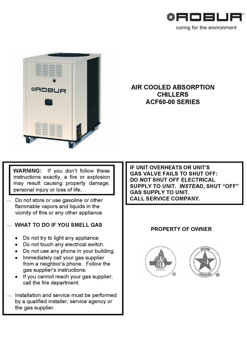
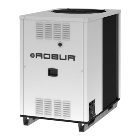
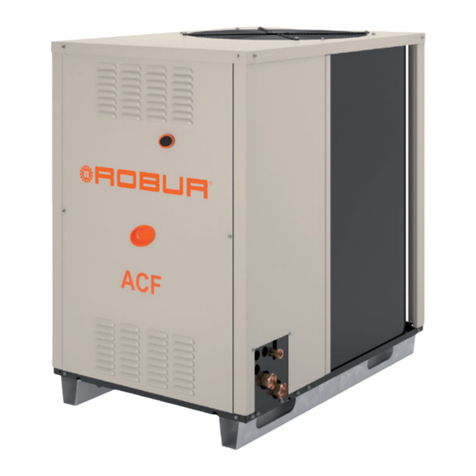
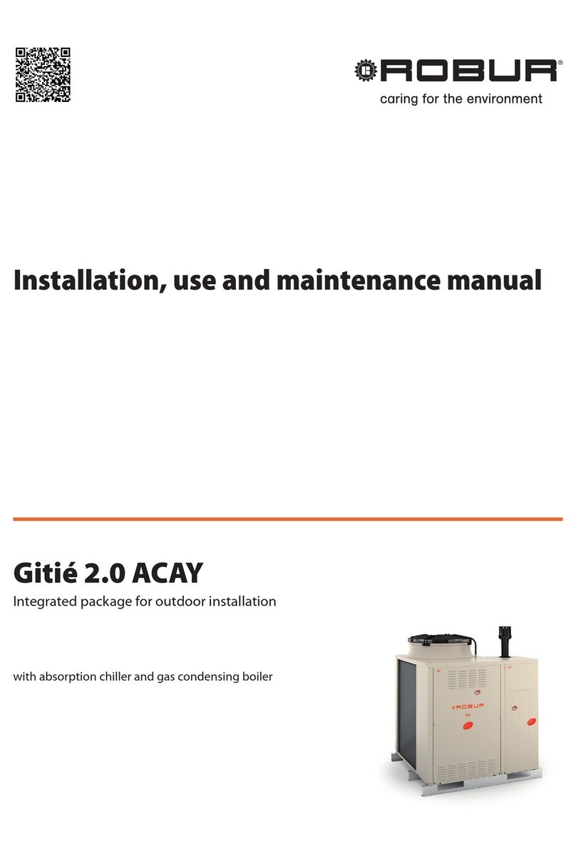
Robur ACF 60-00 User manual

GA Line ACF 60-00 Model
Gas fired absorption chiller
for cooling medium-large areas
Natural gas/LPG fired
Installation, use and
maintenance manual


INDEX
1. GENERAL WARNINGS ................................................................................................3
2. OVERVIEW AND TECHNICAL DATA..........................................................................5
2.1 OVERVIEW .............................................................................................................5
2.2 GAS FIRED CHILLER OPERATION CYCLE ..........................................................6
2.3 TECHNICAL DATA: ACF60-00 (STANDARD, HR, HT, TK, LB VERSIONS) ..........8
STANDARD VERSION ............................................................................................ 8
HT VERSION ......................................................................................................... 10
TK VERSION ......................................................................................................... 13
ACF60-00 UNIT INTERNAL PRESSURE DROP (Standard, HT, TK versions) ...15
LB VERSIONS ....................................................................................................... 16
ACF60-00 LB UNIT INTERNAL PRESSURE DROP ............................................. 20
HR VERSION ........................................................................................................ 21
ACF60-00 HR UNIT INTERNAL PRESSURE DROP OPERATION FOR AIR
CONDITIONING ONLY (NO RECOVERY) ............................................................ 26
ACF60-00 HR HEAT RECOVERY UNIT INTERNAL PRESSURE DROP............. 26
2.4 DIMENSIONS ........................................................................................................27
3. INSTALLATION ..........................................................................................................28
3.1 GENERAL RULES.................................................................................................28
3.2 INSTALLATION OF THE UNIT..............................................................................29
4. HYDRONIC AND GAS INSTALLATION.....................................................................33
4.1 WATER PIPING DESIGN AND INSTALLATION ...................................................33
4.2 GAS SUPPLY PIPING ...........................................................................................37
5. ELECTRICAL CONNECTION.....................................................................................38
5.1 POWER SUPPLY AND PUMP WIRING FOR A SINGLE ACF60-00 UNIT ...........38
5.2 POWER SUPPLY AND PUMP WIRING FOR 2 OR MORE ACF60-00 UNITS......40
5.3 CONTROL SWITCH WIRING AND THERMOSTAT LOCATION...........................41
5.4 ACF60-00 WIRING ................................................................................................42
5.5 DDC CONNECTION ..............................................................................................43
6. START-UP AND ADJUSTMENT ................................................................................51
6.1 FILLING THE WATER PIPING ..............................................................................51
6.2 GAS PRESSURE ADJUSTEMENT .......................................................................54
6.3 CHILLED WATER TEMPERATURE REGULATION..............................................56
7. SERVICING AND MAINTENANCE.............................................................................57
8. ADAPTING TO ANOTHER GAS.................................................................................59
9. SPARE PARTS...........................................................................................................60
10. APPENDIX ..................................................................................................................68
TABLE OF OPERATING CODES GENERATED BY ELECTRONIC BOARD (firmware
version 3.027) .................................................................................................................72

Installation, Start-Up, Adjustment and Maintenance Manual
2
Carefully read the information contained in this manual. It contains important instructions regarding installation,
use and maintenance safety. Save this manual for any future needs. The manufacturer cannot be held
responsible for any damages from improper, erroneous or irrational use.
With the aim of continuously improving the quality of our products, manufacturer reserves the right to change
reported instructions and drawings without any prior notice.
NOTE

Installation, Start-Up, Adjustment and Maintenance Manual 3
1. GENERAL WARNINGS
This manual is an integral and essential part of the product and must be given to the owner.
Only qualified technicians, strictly complying with the manufacturer’s instructions and the local standards,
should install this product. The manufacturer will not accept responsibility for personal injuries or property
damage resulting from improper installation.
Qualified technicians are those having specific technical competence in air conditioning and gas appliances
according to international and national standards.
This appliance must be used exclusively for its intended purpose. All chilling applications must be in
accordance with the operating specifications of the unit. Any other use is considered improper and,
therefore, dangerous. Steps must be taken to avoid improper use and potential dangers.
The fluids used in the sealed refrigerant circuit may cause health problems if inhaled, ingested or when
allowed to come into contact with the skin. It is recommended that no work be performed on the sealed
refrigerant circuit except by a qualified service technician or engineer. Care should also be taken not to
disturb or handle the valves of the chiller’s sealed refrigerant circuit.
The manufacturer will not accept contractual or non-contractual liability for damages resulting from improper
installation or misuse of the unit or intentional disregard of any of the manufacturer’s instructions.
After unpacking the unit, check the unit for integrity. Due to the potential danger, keep all packaging
materials (plastic bags, polystyrene foam, nails, etc.) away from children.
Before installation, it is recommended that all chilled water and gas supply piping be flushed. If not flushed
prior to installation, residual materials may be left in the piping that could cause improper functioning of the
chiller.
The installation of the appliance must conform to the requirements of the authority having jurisdiction or in
the absence of such requirements, to the latest edition of the National Fuel Gas Code, ANSI Z223.1. If the
unit is installed in Canada, the installation must conform to the Canadian Gas Association Standard CAN1
B149.1 and .2.
The chiller’s electrical connections and grounding must be in accordance with the latest edition of the
National Electrical Codes, ANSI/NFPA No. 70 (CSA Standard C22.1 when installed in Canada) and with
any local codes. To ensure the electrical safety of this appliance, it must be correctly connected to an
efficient grounding system. The manufacturer is not responsible for any damages caused by the failure of
the grounding system.
In the case of failure and/or poor unit performance, shut the unit down in the proper manner, disconnect the
UNIT power supply and close the gas valve. Do not attempt any repair and call a qualified technician for
service. The chiller should also be disconnected when not in use for a prolonged period of time.
The manufacturer’s authorized Service Technicians or authorized Service Engineer (TAC), using only
original replacement parts, must perform repairs to the product. Failure to adhere to this guideline may
compromise the safety of the unit. To ensure the correct operation and efficiency of the unit, it is essential
that qualified service technicians perform annual maintenance in accordance with the manufacturer’s
instructions.

Installation, Start-Up, Adjustment and Maintenance Manual
4
If the unit is sold or transferred to another owner, this manual will be provided for use to the new owner
and/or installer.
Under no circumstances should the unit be operated with any safety or electrical component by-
passed or defective.
Do not use this appliance if any part has been under water. Immediately call a qualified service
technician to inspect the appliance and to replace any part of the control system and any gas
control, which has been under water.
Before starting the appliance:
A qualified service technician must verify that:
- The electric and gas supplies are the same as indicated on the rating plate
- The fuel supply and water distribution systems are water tight
- The appliance is supplied with the type of fuel for which it is preset
- The gas supply pressure conforms to the pressure indicated on the rating plate
- The gas supply system is appropriately designed for the gas rate needed by the unit, and equipped with
all safety and control devices prescribed by standards in force.
To guarantee the correct operation of the unit and avoid possible failures, ALWAYS turn off the unit by
means of the thermostat or any switch that controls the operation of the unit.
NEVER turn off the unit by shutting off the power supply.
WARNING

Installation, Start-Up, Adjustment and Maintenance Manual 5
2. OVERVIEW AND TECHNICAL DATA
2.1 OVERVIEW
The High Efficiency Chillers ACF60-00 series are water chillers, equipped with an air-cooled condenser and
designed for outdoor installation. The absorption cooling cycle is based upon a solution of water and
ammonia for the production of chilled water (temperature of chilled water is given by Technical Tables).
The chilling system is fed by thermal energy provided by a gas burner, therefore the required electric energy
is limited to driving the fan and pump motors (the only mechanical moving components of the unit). The
evacuation of combustion gases occurs by mixing them with condenser air using an axial fan of the
appliance. The combustion fuel is Natural Gas or LPG.
The STANDARD and HT versions are designed for the commercial and industrial air-conditioning
applications in the hot climate areas.
The TK versions are designed for the air-conditioning and refrigeration of technological applications (for
example, in the industrial process, that could require chilled water up to 24h a day).
The LB versions are designed for the low temperature refrigeration applications (for example cold rooms for
food conservation).
ACF60-00 HR, “Heat Recovery”. This is an ACF60-00 with a heat recovery system able to provide 60,500
Btu/hr of nominal cooling capacity when operating without the heat recovery system. With the heat recovery
system, it can obtain a cooling capacity of 61,234 Btu/hr, at the same time providing 86,400 Btu/hr of heating
capacity.
For further information see next paragraph, technical data.
ACF60-00 units are Natural Gas or LPG fired and supplied with 208 - 230V 60Hz single-phase electrical
power.
ACF60-00 units could be controlled by DDC - Direct Digital Controller
(available as Optional). DDC can control up to 16 single chillers.
Figure 1 - Direct Digital Controller
CHILLER’S CONTROL AND SAFETY DEVICES
Electronic Control Board with integrated microprocessor controls the operation of the chiller.
High Temperature Limit Switch (manual reset) is located at the generator wall above the combustion
chamber; the switch opens if the generator's sidewall temperature exceeds 330°F; the switch is manual
reset. The switch can be reset when the generator sidewall temperature drops below 280°F.
Safety Relief Valve on the sealed circuit.
Differential Air Pressure Switch on the combustion circuit stops the burner ignition due to insufficient
combustion air flow.
Ignition Control Box controls the burner ignition. Checks the differential air pressure switch and starts the
pre-mixer blower. After 30 seconds of purging, the ignition control box opens the gas valve and starts the
ignition transformer sparking at the burner for 8 seconds. If no flame is detected, the ignition control box will
close the gas valve and retry lighting after an inter-purge period of 30 seconds. The ignition control box will
try a total of three times to light. The unit will stop if no flame has been established or detected after the 3
tries.
Dual Gas Valve: two gas valves in the same housing, electrically controlled, which positively stops gas flow
when either closes.

Installation, Start-Up, Adjustment and Maintenance Manual
6
Flow Switch monitors the chilled water flow and shuts down the unit when the water flow stops or drops to
an insufficient level.
2.2 GAS FIRED CHILLER OPERATION CYCLE
The fluid used in the cooling cycle is a solution of water and ammonia (see Figure 2). Ammonia is the
refrigerant and water is the absorbing fluid. In the chiller’s generator, the ammonia-water solution is heated
to boiling by a burner producing both a vapor with a strong concentration of ammonia and a liquid solution
with a low concentration of ammonia. Liquid solution with a low concentration of ammonia is called a "weak
solution".
The ammonia vapor passes into the rectifier, which separates the water from the vapor. The hot and
pressurized ammonia vapor exiting the rectifier enters the condenser where it is cooled and changed to a
liquid.
The liquid ammonia is then brought to a lower pressure by means of a restrictor and further cooled in a
“tube-in-tube” refrigerant heat exchanger. Finally, the liquid ammonia is reduced to a pressure of 39 to 60
psig and a temperature lower than 37°F by a second restrictor.
Under this low pressure and temperature condition, liquid ammonia enters the evaporator where the
ammonia evaporates due to heat being removed from water returning from the user's required cooling
application (thermal blowers, fan-coils, etc.) within the chilled water system.
The cold, low-pressure ammonia vapor exiting the evaporator exchanges heat with the liquid ammonia
coming from the condenser in the refrigerant heat exchanger. The ammonia vapor then enters the “solution
cooled absorber” where it comes into contact with "weak solution" from the generator that has been brought
to a low pressure by means of a restrictor.
Inside the “solution cooled absorber” the absorption process starts, i.e. the dilution of ammonia vapor into the
"weak solution". The absorption of ammonia vapor is an exothermic process. (i.e. heat is produced) To have
the vapor completely absorbed by the solution, the solution exiting the “solution cooled absorber” must be
further cooled in a portion of the condenser/absorber coils.
Once the absorption process is complete, the liquid solution contains a high concentration of ammonia, also
called "strong solution". A hydraulically driven, diaphragm solution pump pumps the “strong solution” to the
generator at high pressure.
As the “strong solution” is pumped to the generator, it passes through the coil of the rectifier and the solution
cooled absorber (the GAX section) where it is preheated before entering the generator. The cycle then
starts over.

Installation, Start-Up, Adjustment and Maintenance Manual 7
Figure 2– ABSORPTION REFRIGERANT CYCLE
EVAPORATOR
TUBE-IN-TUBE REFRIGERANT
HEAT EXCHANGER
SOLUTION
PUMP
SOLUTION COOLED
A
BSORBER
GENERATOR
RECTIFIER
BURNER
WEAK STRONG REFRIGERANT REFRIGERANT CHILLED
SOLUTION SOLUTION VAPOR LIQUID WATER
CONDENSER / ABSORBER
RESTRICTORS
ACF60-00

Installation, Start-Up, Adjustment and Maintenance Manual
8
2.3 TECHNICAL DATA: ACF60-00 (STANDARD, HR, HT, TK, LB VERSIONS)
STANDARD VERSION
PERFORMANCE RATINGS1UNITS
ACF60-00
Cooling Capacity2Nominal Btu/hr 60,500
Gas Input (HHV) Nominal Btu/hr 94,900
°F 120
Ambient Operating Temperature Maximum
Minimum °F 32
Condenser Air Flow3Nominal
Minimum
CFM
CFM
6,000
2,000
Inlet (to the unit) Chilled Water
Temperature Maximum °F 113
Outlet (to plant) Chilled Water
Temperature Minimum °F 37.4
Chilled Water Flow
Nominal
Maximum
Minimum
GPM
12.2
14.1
11.0
Internal Pressure Drop Feet of Head
psig
9.7
4.2
ELECTRICAL RATINGS
Required Voltage, 60 Hz, Single
Phase4V 208 - 230
Condenser Fan Motor HP
(Variable Speed)
Full Load / Locked Rotor
Nominal -
A
1/2
3.1 / 6.2
Hydraulic Pump Motor HP
Full Load / Locked Rotor Nominal -
A
1/2
3.1 / 24.2
Premix Blower Motor HP
Full Load / Locked Rotor Nominal -
A
1/50
.55 / .75
Total Electrical Operating
Consumption5
(Unit only)
kW .75
Minimum Circuit Ampacity
(MCA) (Unit only) A 8.0
Maximum Over Current
Protection (MOCP)
Qty (2) - Field Supplied
A 10.9
PHYSICAL DATA
Refrigerant Type - R717
Unit Chilled Water Volume6Gallons 0.79
Chilled Water Entering and
Leaving Connections7FPT 1” 1/4
Gas Inlet Connection FPT 1/2
Electrical Entrance Knockouts,
Diameter Inches 7/8
Shipping Weight Pounds 795
Operating Weight Pounds 750
Width 331/2
Length 481/2
Dimensions
Height
Inches
503/4
Table 1 – ACF60-00 TECHNICAL DATA

Installation, Start-Up, Adjustment and Maintenance Manual 9
Notes:
1. All illustrations and specifications contained herein are based on the latest information available at the time of publication approval.
Robur reserves the right to make changes at any time without notice, in materials, specifications, and models or to discontinue
models.
2. Capacity at standard conditions of 95°F ambient temperature. Chilled water Outlet temperature 45°F, chilled water Inlet
temperature 55°F. Actual capacity will vary with ambient (condenser) air temperature and leaving water temperature. Capacity
characteristics are shown in the table below. Interpolations between tabled values are permissible, but do not extrapolate. For
capacities at ambient temperatures higher than in table, contact Robur or your authorized distributor.
3. Fan speed is reduced when external temperature is less than 91.4°F.
4. Units are factory-wired for 208-230 volts operation.
5. May vary by ±10% as a function of both power supply and electrical motor input tolerance.
6. "Chilled Water" refers to a solution of quality tap water and 10% by volume of inhibited permanent antifreeze. Higher antifreeze
concentrations may be required in certain applications.
7. Mono-ethylene glycol causes corrosion phenomenon in galvanized metal pipes.
COOLING CAPACITY in Btu/hr
Table 2 – ACF60-00 COOLING CAPACITY
OUTLET CHILLED WATER (°F)
AMBIENT AIR
TEMPERATURE (°F) 37.4 41.0 44.6 48.2
32 59,307 59,912 61,123 62,323
41 59,307 59,912 61,123 62,333
50 59,307 59,912 61,123 62,323
59 59,307 59,912 61,123 62,333
68 59,307 59,912 61,123 62,323
77 58,701 59,912 61,123 62,333
86 54,465 59,307 61,123 62,333
95 40,546 52,650 60,517 61,727
104 - - 53,255 56,281
113 - - 40,546 47,203
120 - - - 39,336

Installation, Start-Up, Adjustment and Maintenance Manual
10
HT VERSION
PERFORMANCE RATINGS1UNITS
ACF60-00 HT
Cooling Capacity2Nominal Btu/hr 58,400
Gas Input (HHV) Nominal Btu/hr 94,900
°F 131
Ambient Operating Temperature Maximum
Minimum °F 32
Condenser Air Flow3Nominal
Minimum
CFM
CFM
6,000
2,000
Inlet (to the unit) Chilled Water
Temperature Maximum °F 113
Outlet (to plant) Chilled Water
Temperature Minimum °F 41
Chilled Water Flow
Nominal
Maximum
Minimum
GPM
11.8
14.1
11.0
Internal Pressure Drop Feet of Head
psig
9.1
3.9
ELECTRICAL RATINGS
Required Voltage, 60 Hz, Single
Phase4V 208 - 230
Condenser Fan Motor HP
(Variable Speed)
Full Load / Locked Rotor
Nominal -
A
1/2
3.1 / 6.2
Hydraulic Pump Motor HP
Full Load / Locked Rotor Nominal -
A
1/2
3.1 / 24.2
Premix Blower Motor HP
Full Load / Locked Rotor Nominal -
A
1/50
.55 / .75
Total Electrical Operating
Consumption5
(Unit only)
kW .75
Minimum Circuit Ampacity
(MCA) (Unit only) A 8.0
Maximum Over Current
Protection (MOCP)
Qty (2) - Field Supplied
A 10.9
PHYSICAL DATA
Refrigerant Type - R717
Unit Chilled Water Volume6Gallons 0.79
Chilled Water Entering and
Leaving Connections7FPT 1” 1/4
Gas Inlet Connection FPT 1/2
Electrical Entrance Knockouts,
Diameter Inches 7/8
Shipping Weight Pounds 860
Operating Weight Pounds 816
Width 331/2
Length 481/2
Dimensions
Height
Inches
503/4
Table 3 – ACF60-00 HT TECHNICAL DATA

Installation, Start-Up, Adjustment and Maintenance Manual 11
Notes:
1. All illustrations and specifications contained herein are based on the latest information available at the time of publication approval.
Robur reserves the right to make changes at any time without notice, in materials, specifications, and models or to discontinue
models.
2. Capacity at standard conditions of 95°F ambient temperature. Chilled water Outlet temperature 45°F, chilled water Inlet
temperature 55°F. Actual capacity will vary with ambient (condenser) air temperature and leaving water temperature. Capacity
characteristics are shown in the table below. Interpolations between tabled values are permissible, but do not extrapolate. For
capacities at ambient temperatures higher than in table, contact Robur or your authorized distributor.
3. Fan speed is reduced when external temperature is less than 91.4°F.
4. Units are factory-wired for 208-230 volts operation.
5. May vary by ±10% as a function of both power supply and electrical motor input tolerance.
6. "Chilled Water" refers to a solution of quality tap water and 10% by volume of inhibited permanent antifreeze. Higher antifreeze
concentrations may be required in certain applications.
7. Mono-ethylene glycol causes corrosion phenomenon in galvanized metal pipes.

Installation, Start-Up, Adjustment and Maintenance Manual
12
COOLING CAPACITY in Btu/hr
Table 4 – ACF60-00 HT COOLING CAPACITY
OUTLET CHILLED WATER (°F)
AMBIENT AIR
TEMPERATURE (°F) 41.0 44.6 50.0 54.5 57.2
32.0 59,637 59,637 59,637 59,637 60,222
35.6 59,637 59,637 59,637 59,637 60,222
39.2 59,637 59,637 59,637 59,637 60,222
42.8 59,637 59,637 59,637 59,637 60,222
46.4 59,637 59,637 59,637 59,637 60,222
50.0 59,637 59,637 59,637 59,637 60,222
53.6 59,637 59,637 59,637 59,637 60,222
57.2 59,637 59,637 59,637 59,637 60,222
60.8 59,637 59,637 59,637 59,637 60,222
64.4 59,637 59,637 59,637 59,637 60,222
68.0 59,637 59,637 59,637 59,637 60,222
71.6 59,637 59,637 59,637 59,637 60,222
75.2 59,637 59,637 59,637 59,637 60,222
78.8 59,053 59,637 59,637 59,637 60,222
82.4 59,053 59,637 59,637 59,637 60,222
86.0 59,053 59,637 59,637 59,637 60,222
89.6 57,883 59,637 59,637 59,637 60,222
93.2 56,129 59,053 59,053 59,053 59,637
95.0 54,960 58,368 58,468 59,053 59,637
96.8 53,791 57,883 58,468 58,468 59,637
100.4 50,867 56,714 57,883 57,883 59,053
104.0 47,944 54,375 56,714 57,299 58,468
107.6 - 51,452 54,960 56,714 57,883
111.2 - 47,944 53,206 55,545 56,714
114.8 - - 50,282 53,791 55,545
118.4 - - 46,774 50,867 53,206
131.0 - - - 47,359 50,282

Installation, Start-Up, Adjustment and Maintenance Manual 13
TK VERSION
PERFORMANCE RATINGS1UNITS
ACF60-00 TK
Cooling Capacity2Nominal Btu/hr 60,500
Gas Input (HHV) Nominal Btu/hr 94,900
°F 120
Ambient Operating Temperature Maximum
Minimum °F 10.4
Condenser Air Flow3Nominal
Minimum
CFM
CFM
6,000
2,000
Inlet (to the unit) Chilled Water
Temperature Maximum °F 113
Outlet (to plant) Chilled Water
Temperature Minimum °F 37.4
Chilled Water Flow
Nominal
Maximum
Minimum
GPM
12.2
14.1
11.0
Internal Pressure Drop Feet of Head
psig
9.7
4.2
ELECTRICAL RATINGS
Required Voltage, 60 Hz, Single
Phase4V 208 - 230
Condenser Fan Motor HP
(Variable Speed)
Full Load / Locked Rotor
Nominal -
A
1/2
3.1 / 6.2
Hydraulic Pump Motor HP
Full Load / Locked Rotor Nominal -
A
1/2
3.1 / 24.2
Premix Blower Motor HP
Full Load / Locked Rotor Nominal -
A
1/50
.55 / .75
Total Electrical Operating
Consumption5
(Unit only)
kW .75
Minimum Circuit Ampacity
(MCA) (Unit only) A 8.0
Maximum Over Current
Protection (MOCP)
Qty (2) - Field Supplied
A 10.9
PHYSICAL DATA
Refrigerant Type - R717
Unit Chilled Water Volume6Gallons 0.79
Chilled Water Entering and
Leaving Connections7FPT 1” 1/4
Gas Inlet Connection FPT 1/2
Electrical Entrance Knockouts,
Diameter Inches 7/8
Shipping Weight Pounds 860
Operating Weight Pounds 816
Width 331/2
Length 481/2
Dimensions
Height
Inches
503/4
Table 5 – ACF60-00 TK TECHNICAL DATA

Installation, Start-Up, Adjustment and Maintenance Manual
14
Notes:
1. All illustrations and specifications contained herein are based on the latest information available at the time of publication approval.
Robur reserves the right to make changes at any time without notice, in materials, specifications, and models or to discontinue
models.
2. Capacity at standard conditions of 95°F ambient temperature. Chilled water Outlet temperature 45°F, chilled water Inlet
temperature 55°F. Actual capacity will vary with ambient (condenser) air temperature and leaving water temperature. Capacity
characteristics are shown in the table below. Interpolations between tabled values are permissible, but do not extrapolate. For
capacities at ambient temperatures higher than in table, contact Robur or your authorized distributor.
3. Fan speed is reduced when external temperature is less than 91.4°F.
4. Units are factory-wired for 208-230 volts operation.
5. May vary by ±10% as a function of both power supply and electrical motor input tolerance.
6. "Chilled Water" refers to a solution of quality tap water and 10% by volume of inhibited permanent antifreeze. Higher antifreeze
concentrations may be required in certain applications.
7. Mono-ethylene glycol causes corrosion phenomenon in galvanized metal pipes.
COOLING CAPACITY in Btu/hr
Table 6 – ACF60-00 TK COOLING CAPACITY
OUTLET CHILLED WATER (°F)
AMBIENT AIR
TEMPERATURE (°F) 37.4 41.0 44.6 48.2
10.4 71,410 71,410 72,015 72,620
17.6 70,805 70,805 71,410 72,015
24.8 70,200 70,200 70,200 71,410
32.0 69,595 69,595 69,595 70,200
39.2 68,989 68,989 68,989 69,595
46.4 67,779 68,384 68,384 68,989
53.6 67,779 67,779 67,779 68,384
60.8 67,174 67,174 67,779 67,779
68.0 65,964 65,964 67,174 67,174
75.2 64,148 64,148 66,569 66,569
82.4 59,307 61,727 65,358 65,358
89.6 51,439 57,491 62,938 64,148
95.0 41,757 52,650 60,517 62,333
100.4 - - 56,886 59,912
107.6 - - 50,229 55,070
113.0 - - - 49,624
120.0 - - - 42,057

Installation, Start-Up, Adjustment and Maintenance Manual 15
ACF60-00 UNIT INTERNAL PRESSURE DROP (Standard, HT, TK versions)
Graph 1- UNIT PRESSURE DROP AS A FUNCTION OF WATER FLOW, OUTLET WATER TEMPERATURE 44.6 °F
2.00
4.00
6.00
8.00
10.00
12.00
6.00 7.00 8.00 9.00 10.00 11.00 12.00 13.00 14.00 15.00
PRESSURE DROP (FEET OF HEAD)
WATER FLOW (GPM)
ACF60-00,
HT, TK

Installation, Start-Up, Adjustment and Maintenance Manual
16
LB VERSIONS
PERFORMANCE RATINGS1UNITS
ACF60-00 LB
Cooling Capacity2Nominal Btu/hr 45,400
Gas Input (HHV) Nominal Btu/hr 94,900
°F 120
Ambient Operating Temperature Maximum
Minimum °F 10.4
Condenser Air Flow3Nominal
Minimum
CFM
CFM
6,000
2,000
Inlet (to the unit) Chilled Water
Temperature Maximum °F 113
Outlet (to plant) Chilled Water
Temperature Minimum °F 14
Chilled Water Flow
Nominal
Maximum
Minimum
GPM
11.4
12.8
10.1
Internal Pressure Drop Feet of Head
psig
14.1
6.1
ELECTRICAL RATINGS
Required Voltage, 60 Hz, Single
Phase4V 208 - 230
Condenser Fan Motor HP
(Variable Speed)
Full Load / Locked Rotor
Nominal -
A
1/2
3.1 / 6.2
Hydraulic Pump Motor HP
Full Load / Locked Rotor Nominal -
A
1/2
3.1 / 24.2
Premix Blower Motor HP
Full Load / Locked Rotor Nominal -
A
1/50
.55 / .75
Total Electrical Operating
Consumption5
(Unit only)
kW .75
Minimum Circuit Ampacity
(MCA) (Unit only) A 8.0
Maximum Over Current
Protection (MOCP)
Qty (2) - Field Supplied
A 10.9
PHYSICAL DATA
Refrigerant Type - R717
Unit Chilled Water Volume Gallons 0.79
Chilled Water Entering and
Leaving Connections6FPT 1” 1/4
Gas Inlet Connection FPT 1/2
Electrical Entrance Knockouts,
Diameter Inches 7/8
Shipping Weight Pounds 860
Operating Weight Pounds 816
Width 331/2
Length 481/2
Dimensions
Height
Inches
503/4
Table 7 – ACF60-00 LB TECHNICAL DATA

Installation, Start-Up, Adjustment and Maintenance Manual 17
Notes:
1. All illustrations and specifications contained herein are based on the latest information available at the time of publication approval.
Robur reserves the right to make changes at any time without notice, in materials, specifications, and models or to discontinue
models.
2. Capacity at standard conditions of 95°F ambient temperature. Chilled water Outlet temperature (40% mono-ethylene glycol) 23°F,
chilled water Inlet temperature 32°F. Actual capacity will vary with ambient (condenser) air temperature and leaving water
temperature. Capacity characteristics are shown in the table below. Interpolations between tabled values are permissible, but do
not extrapolate. For capacities at ambient temperatures higher than in table, contact Robur or your authorized distributor.
3. Fan speed is reduced when external temperature is less than 91.4°F.
4. Units are factory-wired for 208-230 volts operation.
5. May vary by ±10% as a function of both power supply and electrical motor input tolerance.
6. Mono-ethylene glycol causes corrosion phenomenon in galvanized metal pipes.

Installation, Start-Up, Adjustment and Maintenance Manual
18
COOLING CAPACITY in Btu/hr
OUTLET CHILLED WATER (°F)
AMBIENT AIR
TEMPERATURE (°F) 14.0 19.4 23.0 28.4 32.0
23.0 52,007 52,217 52,426 52,801 53,176
24.8 52,007 52,217 52,426 52,801 53,176
26.6 52,007 52,217 52,426 52,801 53,176
28.4 52,007 52,217 52,426 52,801 53,176
30.2 52,007 52,217 52,426 52,801 53,176
32.0 52,007 52,217 52,426 52,801 53,176
33.8 52,007 52,217 52,426 52,801 53,176
35.6 52,007 52,217 52,426 52,801 53,176
37.4 52,007 52,217 52,426 52,801 53,176
39.2 52,007 52,217 52,426 52,801 53,176
41.0 52,007 52,217 52,426 52,801 53,176
42.8 52,007 52,217 52,426 52,801 53,176
44.6 52,007 52,217 52,426 52,801 53,176
46.4 52,007 52,200 52,392 52,784 53,176
48.2 52,007 52,183 52,358 52,767 53,176
50.0 52,007 52,166 52,324 52,750 53,176
51.8 51,965 52,127 52,290 52,733 53,176
53.6 51,904 52,080 52,256 52,716 53,176
55.4 51,822 52,022 52,221 52,699 53,176
57.2 51,718 51,952 52,187 52,681 53,176
59.0 51,588 51,884 52,181 52,678 53,176
60.8 51,430 51,793 52,157 52,666 53,176
62.6 51,241 51,677 52,113 52,644 53,176
64.4 51,020 51,533 52,047 52,610 53,172
66.2 50,763 51,360 51,957 52,563 53,169
68.0 50,469 51,155 51,841 52,503 53,166
69.8 50,134 50,915 51,696 52,423 53,149
71.6 49,757 50,638 51,520 52,314 53,107
73.4 49,334 50,322 51,311 52,174 53,038
75.2 48,864 49,965 51,067 52,002 52,937
77.0 48,343 49,564 50,785 51,795 52,805
Table of contents
Other Robur Chiller manuals
Popular Chiller manuals by other brands

evoheat
evoheat Evo Control 8 Installation & operation

McQuay
McQuay PFS 155C Operation and maintenance manual

Carrier
Carrier 30HR Series installation instructions

KKT chillers
KKT chillers vBoxX 6 Translation of the original operating manual

Trane
Trane RTWD Installation operation & maintenance

BERJAYA
BERJAYA BS 2DC4/Z Service manual