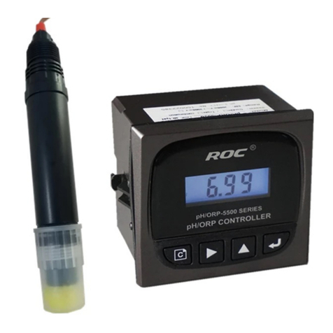
ROC pH/ORP-5500 Series User manual

pH/ORP-5500 Series
pH/ORP Transmitting Controller
Instruction Manual

Notes before Operation
1. Notice before operation:
(1) Carefully read the relevant parts of this manual before installation and operation to prevent wrong
operation, measurement error and damage of instrument.
(2) Improper installation and unsuitable flow speed will cause big measurement error, so please read the
installation passage in detail.
(3) This instrument is precise electrochemical measurement, and its installation and operation should be
performed by technicians with relevant professional knowledge.
(4) If for some special conditions, please consult our Technical Department for further details.
2. Maintenance items:
(1) The indicators’ quality guarantee is one year from the date of purchasing. During this period, if the
meter has quality problems, manufacturer is responsible for maintenance work for free or changes it.
(2) pH and ORP probes are consumer goods which without quality guarantee. Because, the lifespan is based
on the medium and working conditions.
(3) Manufacturer offers the maintenance service for whole life of the sold meters.
(4) If the damage of the meter is caused by the following reasons, it is out of the maintenance service:
A、The meter is burned or foundered caused by improper usage and maintenance.
B、The meter is refitted or misused without permit.
C、The meter is destroyed under the condition out of company’s regulation.
D、The relevant damage caused by choosing the wrong type.
E、The cable damage and rupture caused by improper installation and usage.
F、The incorrect measurement of the probe caused by disconnecting or connecting wires personally.
G、The measurement inaccurate caused by privately cutting the probe cable.
H、
The inner broken wire caused by indiscreetly disassembling.
I、The consumptive materials are not within the scope the warranty.

CATALOG
ⅠCONCEPTION ..................................................................................................................................1
1.1 MAIN FEATURES..........................................................................................................................1
1.2 APPLICATION ...............................................................................................................................1
1.3 NOTE:...........................................................................................................................................1
1.4 TECHNICAL FEATURES..............................................................................................................2
Ⅱ.INSTRUMENT DIMENSION AND TERMINAL DEFINITION ..................................................3
2.1. INSTRUMENT DIMENSION .......................................................................................................3
2.2. INSTRUMENT REAR TERMINALS DEFINATION ..................................................................4
Ⅲ. EQUIPMENT LAYOUT REFERENCE DIAGRAM .....................................................................5
3.1 MILLIAMPERE TRANSMITTING CONNECTION LAYOUT...................................................5
3.2 ELECTRICAL CONNECTION LAYOUT.....................................................................................5
Ⅳ.OPERATE SETTING.......................................................................................................................6
4.1 PANEL AND MAIN INTERFACE DISPLAY...............................................................................6
4.2 KEY BOARD FUNCTION .............................................................................................................7
4.3 SETTING INTERFACE ..................................................................................................................7
4.4 PROBE CALIBRATION.................................................................................................................8
4.4.1 CALIBRATION ...........................................................................................................................8
ⅤINTRUMENT MATING PROBE INSTALLATION GUIDE..........................................................9
5.1 PROBE OUTLINE DIMENSION...................................................................................................9
5.2 PROBE INSTALLATION ........................................................................................................10
5.3 PROBE INSTALLATION REQUEST..........................................................................................11
Ⅵ、MAINTAINING ..........................................................................................................................12
6.1 PROBE MAINTAINING ..............................................................................................................12
6.2 PROBE USING ATTENTION......................................................................................................12
Ⅶ、INSTRUMENT AND PROBE FAULT COMMON TROUBLE SHOOTING ..........................13
ⅧUNIT ..............................................................................................................................................13
Ⅸ、PURCHARSE INSTRUCTION ..................................................................................................14

ⅠCONCEPTION
pH/ORP-5500 series pH/ORP Transmitting Controller is a popular type,high Cost performance
instrument, mating pH/ORP probe,the entire instrument have high measurement accuracy,
anti-interference,easy installation,simple operate features.
1.1 Main Features
1. LCD screen with prompt code, make every step operating get the presentation and guide;
2. Programming pH&ORP function can be switched,suit any type of pH&ORP probe;
3. Support six types of buffer calibration which can free combination,greatly broaden the
application scope;
4. Innovative manual input calibration method provide the biggest convinence for site
calibration
5. Selectable manual/automatic temperature compensation measurement type,providing the
largest flexibility.
6. Independent external automatic temperature compensation probe provide high measurement
accuracy.
7. Isolated/transferable /Reverse /instrument/Transmitter mode current output,compatible all
the transmitting receive modes.
8. Double relay’s high/low limit and delay control satisfied pH or ORP region control and
dosing;
9. Mating split style、double combination probe easy change,one time wiring,permanent using
(see the pH/ORP1220Aseries instruction);
10. Industrial standard terminals,EMC electromagnetic compatibility measurement,platform
design and development, series grouping;
11. Satisfy world electric power supply standard,DC/AC power input nonpolarity connection,
site operation will not worry about wrong connect;
12. SMT Automatically Surface Mount Technology,AOI Automated Optical Inspection,ICT,
FCT Full Computer Test,quality control means make, reliable quality;
13. Every instrument make aging test,surface processing treatment,Full equipped electrical
productive technology,high quality level;
14. Calibrate the probe one before leave factory;
1.2 Application
This instrument is used for pH/ORP online monitor in environmental protection of water
treatment, purified water treatment, industry process, aquaculture and etc
1.3 Note:
1. The instrument should place in dry environment or control box to avoid the sputtering or
condensation water causing leakage or measurement error
2. This series instrument is platform develop result, various power supply can select, pls pay
attention to the voltage class when install the wiring;
3. long time ultraviolet rays shining will burn the screen,result the gray scale reduce,so avoid installing
direct sunlight place.
1

1.4 Technical features
Model 5500 5510 5520
Power supply DC24V AC110 AC220V
Supply frequency ---------- 50/60 50/60
pH 0.00~ 14.00
ORP -1000mV~ +1000mV
Measurement range
Temp. 0.0 ~99.9℃
pH 0.01
ORP 1mV
Resolution
Temp 0.1℃
pH ≤±0.05
ORP ≤±5 mV
Indication error
Temp ≤±0.5℃
Input impedance cause value
error pH ±0.03
Approx equivalent input impedance 5×10¹²Ω
PH buffer solution 10.0;9.18;7.00;6.86;4.00;4.01
Temp. compensation error pH ≤±0.05
Entire instrument error pH ≤±0.1
pH 0.05
Entire instrument
repeatability error ORP ±2mV
Compensation range Temp. 0 ~ 50℃
Temp. 0 ~ 50℃
Working environment Humidity ≤85% RH
Cable length ≤20m(standard 10m)
Control output double relay(single contact ON/OFF),hysteresis can be set
3A(max), AC220V/AC110V 3A(max), DC24V
Contact capacity
Power consumption <2.5W
Channels One channel
Isolated, transferable, adjustable,
instrument/transmitter mode
Technical features
(4~20)mA current loop
Loop ≤500Ω(max),DC24V
Accuracy ±0.1mA
Protection grade level IP65(with rear cover)
2

Installation Panel mounted, fast installation clamp
Dimension 96 mm×96mm×103 mm (H×W×D)
hole dimension 91mm×91mm
Ⅱ.INSTRUMENT DIMENSION AND TERMINAL DEFINITION
2.1. Instrument dimension
Shell front view
Shell top view Shell side view
3

2.2. Instrument rear terminals defination
.
Wire instruction:
0V/220V AC 220V input terminal (pH/ORP-5520)
0V/110V AC 110V input terminal (pH/ORP-5510)
DC 24V input terminal (pH/ORP-5500)
(Internal automatic recognition of polarity)
24VA/B
EARTH Electromagnetic compatibility earth protection terminal
Hi High limit alarm control terminal blocks
Low Low limit alarm control terminal blocks
T+ (T+、T-)external feed under transmitting mode
T-/I+ public terminal under Transmitter /Instrument Mode
I- (I+、I-) mA output terminal under Instrument mode
INPUT Connect pH/ORP measurement electrode(Clear line)
REF Connect pH/ORP reference electrode(shielding)
CELL-T Connect temp. probe collect terminal(red line)
GND Connect temp. probe earth terminal(black line)
NC Empty terminal
4

Ⅲ. EQUIPMENT LAYOUT REFERENCE DIAGRAM
3.1 Milliampere transmitting connection layout
Instrument mode current loop wiring Transmitter mode current loop wiring
3.2 Electrical connection layout
Relay ON/OFF contact component control wiring diagram
5

3.3 ControlMode
alarm high low limit
setting identification
Units show
identification
pH show
identification
mAmigrate setting
identification
a
Ⅳ.OPERATE SETTING
4.1 Panel and main interface display
6

4.2 Key board function
Keyboard Name Function
1. pH automatic temperature compensation measurement
mode;
2. Ph measurement status to check temperature
compensation value
Return
3. Return or skip the revised item
4. Parameter setting status circulate of thousand hundred
ten one bit symbol
Select 5. pH measurement mode long time press this key,enter
into pH manual mV calibration interface
6. Processing 0~9 setting under parameters setting status.
7. Long time press this key under pH measurement mode,
enter into standard buffer solution calibration interface
Add
8. Check mV value under pH measurement status
9. enter into function setting menu;
Enter 10. confirm the modification item and save
4.3 Setting interface
Under main measurement interface,press“ ”key enter into parameter setting
order Name Function
“pH” or “ORP” flashing,select “Add” key, processing pH、
ORP function selection,press “enter” to save,enter into
next parameter setting。
1 Function selection
4mAflashing,operate “select” & “Add” key set 4mA
4mA corresponding pH
setting
2 corresponding pH value;press“ enter” key save,enter into
next parameter setting(the same below)
20mA corresponding
pH setting
20mAflashing,set 20mA corresponding pH value;confirm
3 and save,enter into next parameter setting
High limit alarm pH
setting
Hi flashing,setting high limit alarm pH value;confirm and
4 save,enter into next parameter setting
Low limit alarm pH
setting
Lo flashing,setting low limit alarm pH value;confirm and
5 save,enter into next parameter setting
Hi & Lo flashing,setting hysteresis pH value;confirm and
Alarm return back lash
pH setting
6 save,enter into next parameter setting(note:min value of
hysteresis setting 0.1pH or 10mV)
pH & ℃flashing,operate “Add” key, processing manual
temp. compensation(H25.0)and automatic
compensation(A25.0) selection,confirm and save,return to
measuring status.
7 Temperature setting
NOTE:This item setting is factory default setting,no
need to change
Note:ORP function setting the same as 1.2.3.4.5.6
7

4.4 Probe calibration
4.4.1 Calibration
pH probe is a kind of electrochemical probe , the sensitivity will reduce after long time usage
and medium. So, the probe needs calibration regularly. The calibration cycle basis on the
medium impact.
1. Normal buffer solution ,10.00\9.18\7.00\6.86\4.00\4.01 can be selected
2. If the measurement medium is acid or alkali, please choose two point slope calibration.
3. If crossing acid or alkali, please choose three kinds of buffer solution to processing three
point calibration.
4. Read the buffer solution configuration before calibrate,correct prepare the buffer solution
is the key point to calibrate.
5. The meter with directly input calibration method, please reference the calibration steps
6. If the probe with long time storage, please put it in the water or KCI solution for 12 hours,
and then calibrate it.
4.4.2 Buffer solution calibration
Select the buffer solution according to the measurement range,correct preparation buffer
according to the instruction;
1. Under pH main measurement interface,press“ ”3 seconds enter into buffer solution
calibration interface,input current buffer solution tempreture,press“enter”key save,enter
into buffer solution calibration interface;
2. “10.00”& pH flashing,indicate enter into buffer solution calibrate selection;press enter key
start calibration(“10.00”flashing),press return key skip it;enter into next calibration menu;
3. Put the cleaned probe into selected buffer solution and wait,calibrate item flashing;
4. After finished calibration, stop flashing,press enter key save,select next item to calibrate,
take out the probe to wash meantime, and put into the buffer solution that the instrument
suggested,complete the selected item calibration in order;
5. calibrateerror“ ”flashing,check the buffer solution configuration correct or not and
recalibrate;
Calibrate operating process as below:
Clean
water
clean the
sensor
10.00
Calibration
solution
Temp. imput
10.00/9.18
solution
7.00/6.86
solution
Clean
water
clean the
sensor
4.01/4.00
solution
7.00 4.01
9.18 6.86 4.00 Measurement
main
enterface
Clean
water
clean the
sensor
Clean
water
clean the
sensor
Put sensor into selected buffer solution to
calibrate
Calib
rate
calib
rate
calib
rate cleanclean
clean
【Note】 “ ”means skip the setting “ ”means save the setting
8

4.4.3 Offline calibration
If it’s not convenient for on site calibration, please use the Lab device to calibrate the probe o.
Firstly, record mV value which relative to the current room temperature, and then input the
value into Offline item. That is manual input calibration.
Under pH measurement main interface press“select” 3s enter into manul calibrate interface,
input the relative mA value of buffer solution with mating probe,press” ”save,return main
interface.
NOTE:input wrong LCD screen display ” ”under any calibrating spot mV value;Press “enter”
key to continue calibration,or press “return” key cancel the calibration and enter into next calibrate
spot.
ⅤINTRUMENT MATING PROBE INSTALLATION GUIDE
5.1 Probe outline dimension
Temp.probe
9

5.2 Probe installation
pH/ORP Flow device (P34A)
installation
pH/ORP Flow device ( P34B )
installation
Temp probe pipeline installation pH/ORP Floating bed style installation
pH/ORP Scaffolding installation(P16) pH/ORP reaction pool installation
10

Flange installation Horizontal installation
[Note]:Recommend using the flow device with needle control valve (P34)
1. Recommend using with needle control valve flow device when install pipeline (model
P34A/B),which can change probe under pressure-bearing、continue condition;
2. Round sensitive glass steep pH probe direct install in the pipeline, it will threaten the
probe when the pipeline pressure change, water hammer or siphon effect,after using
flow device, the probe and atmosphere will communicate, operational states safe and
measure stability
3. When direct install pipeline,pure water measurement value will unstability because the
water is weak electrolyte,sensitive glass film(glass bubble)and salt bridge present
discontinuity open circuit,result the measure value unstability
4. When direct install the pipeline to measure pure water,high concentration KCL of pH
probe and pure water form huge concentration difference,trough liquid abutment
spread into the water largely. Cause the probe lose effectiveness fastly,pollute the pure
water meantime.,make the conductivity under probe downstream of pH probe rise
hugely.
5.3 Probe installation request
Middle 1 1/4 " NPSC straight pipe
thread fitting ; Upright install or
slant install no more than 30 º
bottom 3/4 " NPT taper thread
fitting;
Upright install or slant install
no more than30 º
11

Level installation cannot work
Fall to install cannot wor
k
Ⅵ、MAINTAINING
6.1 Probe maintaining
1. pH probe may not dry storage,soak in with 3.0mol/L KCL solution box;
2. Suggesting according to the measurement media condition clean the probe timely,calibrate
the probe after mating the meter..
3. If probe is slicked by suspended matter,can use 0.01mol/L HCl or NaOH solution to clean,
then use clear water washing up.
4. If the instrument still can not finish the calibration after above method,means the probe can
not use, should change new one;
5. ORP probe platinum ring surface is bright normally,surface suspended matter will influence
the measurement,may use 0.01mol/L HClor NaOH solution cleaning,then use clear water
washing up.
6. Strong oxidation or reduction causing rough surface will effect probe’s response potential,
may use toothpaste lighting the platinum surface,then use clear water washing up.
7. washing cleaned probe suggested immerse into 3.0mol/L KCL solution hydration 6 hours
then use it;
8. When calibrate pH probe and instrument, the buffer solution must processing under 25 .℃
6.2 Probe using attention
1. pH/ORP probe is consumption type probe, it will ineffective after long time storage, so
suggested to buy to use,do not storage;
2. Prohibit sensitive glass-film(glass boll steep)working in hydrofluoric acid, fluorinion and
high concentration sulfion environment.
3. Prohibit using standard configuration pH/ORP probe measure the organic solution which
can soluable PC and ABS(such as CCL4、CHCLCCL2、C4H8O),or it will damage the
probe shell;
4. Using cotton swab and neutral warm cleanser clean the ball sleep and surface of bounds on
liquid,do not use acid or causticity such strong solution or abrasive material.
5. Biopharmaceutical、high pressure sterilization recommend using high temp. glass pH probe
and matting forcing sheath.
6. pH signal belong to weak current signal,the cable should independent,prohibit wiring with
strong current.
12

7. The probe cable is low noise private cable, untried person can not cut or lengthen privately;
8. When measuring Contain tiny particles of fluid pH value, install filter before the probe,
prevent the particle impact the glass ball steep.
Ⅶ、INSTRUMENT AND PROBE FAULT COMMON TROUBLESHOOTING
Possible factor
Phenomenon Judgment analysis and treatment
Electricity
meter no
display
A. Power
impassability A.check instrument power terminal power
B.invite professional person service
B Instrument fault
A.probe installation
error A.rectify and reform the probe installation
B.slow down the flow rate installing the flow
device
B.flow rate too fast
Display
instability C.water quality
unsteady C.using steady water exclude the instrument
reason
D. connector bad
contact D.check connector and contact good
A.put the probe away from the pipeline,using
buffer solution to calibrate
A. Probe fault
B. Cable damage
Measurement
data large
deviation
B.change the probe which can not calibrate
C. Installation dead
area C.analysis and improve measure point or using
flow device
D. Instrument Setting
error D.resetting the instrument parameter
A. Using single calibrating instrument inspect the
instrument 4~20mA;
A. Recelive cell
unreapear
B. Change signal loop cable length,reduce loop
resistance;
B. Large Loop
resistance
Transmitting
and
display
nunconsi
stent
C. Connect mode error C. Checking the instrument and transmitting mode
connecting correct or not;
D. Feed voltage
unusual D. According to feed standard given transmitting power
supply
E. Secondary traffics
error E. Resetting migration correspondence solution
ⅧUNIT
pH/ORP Transmitting controller 1set(including one quick installation clamp)
pH/ORP probe 1 pc ( selectable,cable length 10m)
Flow device 1set(selectable,refer to purchase instruction)
Instrument operating manual 1 book
Probe operating instruction manual 1 book
Certification of inspection 1 pc
13

Ⅸ、PURCHARSE INSTRUCTION
Name of flow device Matting probe Apply to
Automatic observe
control equipment cabinet
or experiment system
P33 intergrated flow device Glass probe
General probe/fission
probe
Pipeline installation
P34A flow device
P34B flow device 1220A fission probe Pipeline installation
P16 top protect case
immersed install assembly
General probe/fission
probe
Open channel or
impounding reservoir
P17 top flange immersed
install assembly
General probe/fission
probe
Stiring reaction kettle and
material tank
Fold immersed install
assembly
General probe/fission
probe
Dirt waste water pool,
aeration basin
General probe/fission
probe
Open channel ,
stream,aquicuture
Floating bed component
High temp. sterilization
glass probe
Biological
Pressure sheath components pharmaceutical, food
fermentation
Noble metal protective
screening
General probe/fission
probe
Contains hard particle
metallurgy and flotation
system
*Without the influence on the operation, any small change or improvement on the products by the
manufacturer will not be notified separately. Please make the object as the standard.
14
Other manuals for pH/ORP-5500 Series
1
This manual suits for next models
3
Table of contents
Other ROC Controllers manuals
Popular Controllers manuals by other brands

Zaber
Zaber X-VSR Series user manual

Smarteh
Smarteh Longo LPC-2.A03 user manual

Dwyer Instruments
Dwyer Instruments Series DH3 Digihelic Operating and installation instruction

NEC
NEC 78K/0 Series user manual

Minebea Intec
Minebea Intec CSD-918 Series operating instructions

OpenSprinkler
OpenSprinkler OpenSprinkler v3 Getting started guide