manuals.online logo
Brands
  1. Home
  2. •
  3. Brands
  4. •
  5. ICM Controls
  6. •
  7. Controllers
  8. •
  9. ICM Controls ICM550 User manual

ICM Controls ICM550 User manual

LIAF236-1
ICM550
DEFROST CONTROL
Replaces
• Grasslin: 010-0011B, DT040, DT140, DTAV40, DTMV, DTSX
• Paragon: 8041, 8045, 8047, 8141, 8143, 8145, 8245, 8247
• Precision: 6041, 6045, 6047, 6141, 6145
• ICM550 defrost control module
• Bracket mount
• Installation guide
• Terminal block & wiring diagram label sheet
• #8 x 1/2” sheet metal screws (3)
• #6 x 1/2” hex head screws (4)
Package Contents
ELECTRICAL SHOCK HAZARD!
Turn off power at the main service panel by removing
the fuse or switching the appropriate circuit breaker
to the OFF position before working on a high voltage
control.
CAUTION!
Installation of the ICM550 shall be performed by trained
technicians only. Adhere to all local and national electric
codes.
WARNING!
Never turn the dial backward, always turn the dial clockwise
to adjust. Do not attempt to touch or adjust the hands of the
clock as this may cause permanent damage to the clock.
> > > CAUTION < < <
Default Wiring Diagram
Specifications
Inputs:
• Nominal voltage range: 120-240 VAC
• Frequency: 60Hz
Outputs:
• Type: Relay
Contact Ratings:
• Compressor: [2]&[4]: 30A R, 1HP@120VAC, 2HP@240VAC
• Electric heat: [1]&[3]: 40A R, 1HP@120VAC, 2HP@240VAC
• Fan: [1]&[F]: 30A R, 1HP@120VAC, 2HP@240VAC
Environmental
• Operating temperature: -40 to +131°F
• Operating humidity: 0-95%, non-condensing
Mechanical
• Construction: Open board (plastic bracket mounted)
• Mounting: Vertical or Horizontal orientation
Timing
• Minimum defrost time: 15 minutes
• Maximum defrost time: 23 hours 45 minutes
• Terminate defrost: Defrost can be terminated by shorting “X to N”
Status LED
• Defrost mode: (Red LED)
• Refrigeration mode: (Green LED)
Terminal Block
“USE COPPER WIRES ONLY”
Tightening torque 15 in-lb.
The following example shows the
clock set to 2:30 PM:
Turn the outer dial clockwise
until the inner clock hands
point to the correct time.
Each tick mark on the outer
dial represents 15 minutes.
The inner dial is representative
of conventional clock, with the
printed “hand” showing the hour
and the physical hand showing the
minute. The time displayed on the inner dial will always
correspond with the time on the outer dial.
To Set the Current Time
Decide the amount of defrost time
necessary for your environment
and the hours which you want
defrost to occur. Next, set the
switches for each 15 minute
interval of defrost you require
by moving the switch to the
outer position.
Each switch represents a 15
minute interval of defrost and
there are 4 intervals per hour.
In this example, the system will begin one defrost cycle at
the 5:00 PM, which will last for 45 minutes (3 intervals). The
unit will resume normal operation at 5:45 PM.
If multiple defrost cycles are required, please select the
appropriate dipswitches to represent each 15 minute interval
throughout the 24 hour period where defrost is desired.
To Set Defrost Time
F 3 N X1 2 4
T-Stat
Fan
Defrost
Heater
120
VAC
L1
L2
Defrost
Thermostat
w/ Fan Delay
K1K2
Switch Position
Mode A
Compressor
Contactor Coil
Solenoid Valve
Table 1 – Mode Switch Selection Table
Grasslin SW1
DT040 A
DT140 A
DTMV A
DTSX A
DTAV40 A/B per system
Time Initiated &
Time Terminated
Paragon Precision SW1
8045 6045 A
8041 6041 A
8047 6047 B
Time Initiated &
Pressure Terminated
Paragon Precision
8245 A
8247 B
Time Initiated & Pressure or
Temperature Terminated
Paragon Precision SW1
8145 6145 A
8141 6141 A
8143 B
Refrigeration Mode: Green light ON and Red light OFF
(K1 NC, K2 NC)
Defrost Mode: Red light ON and Green light OFF
(K1 NO, K2 NO)
Mode “A” Operation
Refrigeration Mode: Red and Green lights OFF
(K1 NC, K2 NO)
Defrost Mode: Red and Green lights ON
(K1 NO, K2 NC)
Mode “B” Operation
Bracket removed from
ICM550. Discard the bracket
and screws.
B
A
The ICM550 correctly
placed in channels (A) with
screw holes secured using
the four plastic standoffs (B)
of the enclosure.
B
Firmly press the board down
with thumbs on both sides
“***” of “C”.
B B
C
A A
B
A
B
A
B
D-ChannelD-Channel
Replace the cover by
aligning the top of the
cover into channel “D”
then press the bottom of
the cover down rmly until
it snaps into place.
B
B
Push plastic tab DOWN
to release the cover and
pull the cover out of the
enclosure.
Push plastic tab DOWN to
release the board.
Pull the bottom of the existing board UP until the board is
detached from the enclosure.
Remove the four screws (circled) to
release the ICM550 from its bracket. The
four holes will be used to connect the
ICM550 to the Grasslin enclosure.
Installing the ICM550 into a Grasslin Enclosure
The Mode selection switch is used to set up the condition of relay K2 based on the model you are replacing (See Table 1). When
set up in Position A, relay K2 is normally closed and will open in defrost. When set up in position B, relay K2 is normally open and
will close in defrost.
Mode Selection Switch
Align the ICM550 so it slides
UP and INTO the plastic
channels (A), while ensuring
the screw holes on the
ICM550 line up with the plastic
standoffs (B) on the enclosure
CCC
D D
LIT P/N ICM PART # SIZE
CREATED
BY
ENG
SIGNOFF DATE
ADDED
TO DC BY DATE DOC ID#
LIAF236-1
ICM550
8.5 x11
JK
JAF
9/27/19
KEM
10/2/2019
000-28-6918 / D

This manual suits for next models

1

Other ICM Controls Controllers manuals

ICM Controls ICM271 User manual

ICM Controls

ICM Controls ICM271 User manual

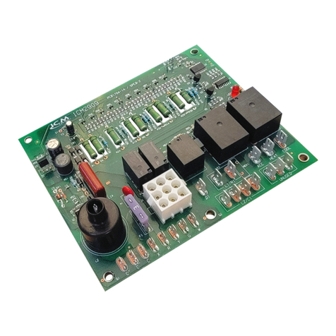
ICM Controls ICM2909 User manual

ICM Controls

ICM Controls ICM2909 User manual

ICM Controls ICM326HN Manual

ICM Controls

ICM Controls ICM326HN Manual

ICM Controls ICM325A General instructions

ICM Controls

ICM Controls ICM325A General instructions

ICM Controls ICM2812ж ICM2812-KIT General instructions

ICM Controls

ICM Controls ICM2812ж ICM2812-KIT General instructions

ICM Controls ICM325A General instructions

ICM Controls

ICM Controls ICM325A General instructions

ICM Controls ICM271 General instructions

ICM Controls

ICM Controls ICM271 General instructions

ICM Controls ICM2810 User manual

ICM Controls

ICM Controls ICM2810 User manual

ICM Controls ICM325HNV General instructions

ICM Controls

ICM Controls ICM325HNV General instructions

ICM Controls ICM2909 User manual

ICM Controls

ICM Controls ICM2909 User manual

ICM Controls ICM1511 Series User manual

ICM Controls

ICM Controls ICM1511 Series User manual

ICM Controls ICM600 User guide

ICM Controls

ICM Controls ICM600 User guide

ICM Controls ICM330 User manual

ICM Controls

ICM Controls ICM330 User manual

ICM Controls ICM2811 General instructions

ICM Controls

ICM Controls ICM2811 General instructions

ICM Controls ICM492 User manual

ICM Controls

ICM Controls ICM492 User manual

ICM Controls ICM870-32A General instructions

ICM Controls

ICM Controls ICM870-32A General instructions

Popular Controllers manuals by other brands

Mitsubishi Electric MELSEC iQ-F FX5 user manual

Mitsubishi Electric

Mitsubishi Electric MELSEC iQ-F FX5 user manual

Specified Controls SC-LLC-200 installation instructions

Specified Controls

Specified Controls SC-LLC-200 installation instructions

TOPP C20 Installation and use instructions

TOPP

TOPP C20 Installation and use instructions

YASKAWA SGD7S-xxxDA0 series product manual

YASKAWA

YASKAWA SGD7S-xxxDA0 series product manual

Munters MUX 2 Manual for use and maintenance

Munters

Munters MUX 2 Manual for use and maintenance

Technogamma tSol VOLTIC user manual

Technogamma

Technogamma tSol VOLTIC user manual

F&F STR-4D manual

F&F

F&F STR-4D manual

Danfoss AK-PC 351 instructions

Danfoss

Danfoss AK-PC 351 instructions

ETC ALiEn2 Quick install guide

ETC

ETC ALiEn2 Quick install guide

ProMinent DULCOMETER D2C operating instructions

ProMinent

ProMinent DULCOMETER D2C operating instructions

Automationdirect.com DirectLOGIC DL205 Series user manual

Automationdirect.com

Automationdirect.com DirectLOGIC DL205 Series user manual

FlowCon FT.0.3 Installation and operation instruction

FlowCon

FlowCon FT.0.3 Installation and operation instruction

Leightronix MINI-T-NX Installation quick guide

Leightronix

Leightronix MINI-T-NX Installation quick guide

Emerson dixell XC10CX Installing and operating instructions

Emerson

Emerson dixell XC10CX Installing and operating instructions

OJ Electronics VCH-3202-DI instructions

OJ Electronics

OJ Electronics VCH-3202-DI instructions

PowerTech MP3755 user manual

PowerTech

PowerTech MP3755 user manual

Danfoss Cascade operating instructions

Danfoss

Danfoss Cascade operating instructions

Honeywell S9200U1000 installation instructions

Honeywell

Honeywell S9200U1000 installation instructions

manuals.online logo
manuals.online logoBrands
  • About & Mission
  • Contact us
  • Privacy Policy
  • Terms and Conditions

Copyright 2025 Manuals.Online. All Rights Reserved.