– 4 –
INSTALLATION CONSIDERATIONS
◆Optical Compression Circuit
The supplied passive crossovers utilize an optical compression circuit for
tweeter protection. This protection circuit absorbs the destructive signal
caused when the amplifier's output is clipped. This greatly increases the
power handling capability and the reliability of the tweeter.
THE RESULT: Increased tweeter reliability under harsh conditions.
◆Passive Filter Bypass
The TX-4186 utilizes an extra screw terminal on the crossover housing
which allows the tweeters audio signal to “bypass” the internal passive
filter. This feature allows an external active filter to be used while
maintaining optical compression for tweeter reliability.
THE RESULT: System flexibility with constant tweeter protection.
Since many of the Punch Splits speakers are designed for direct replace-
ment in factory speaker locations, some of the following instructions will
not apply. To maximize the performance in difficult or custom installa-
tions, please see your Authorized Rockford Fosgate Dealer.
Warning! Please read the entire Installation section before attempting the
installation of your Punch Splits Speakers.
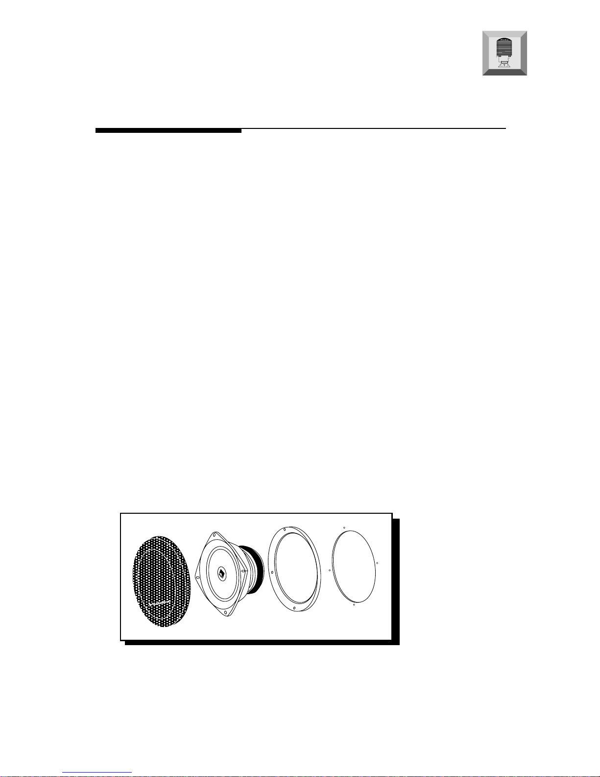
Tools Needed
The following is a list of some of the tools necessary for the installation of
the Punch Splits speakers.
Power Drill with assorted bits Wire Strippers
Volt Meter Wire Crimpers
Assorted Screwdrivers Marking Pen
Tape Measure Hole Saw Arbor
Hole Saw (11⁄4") Assorted Hole Saws
(Tweeter) (Midrange)
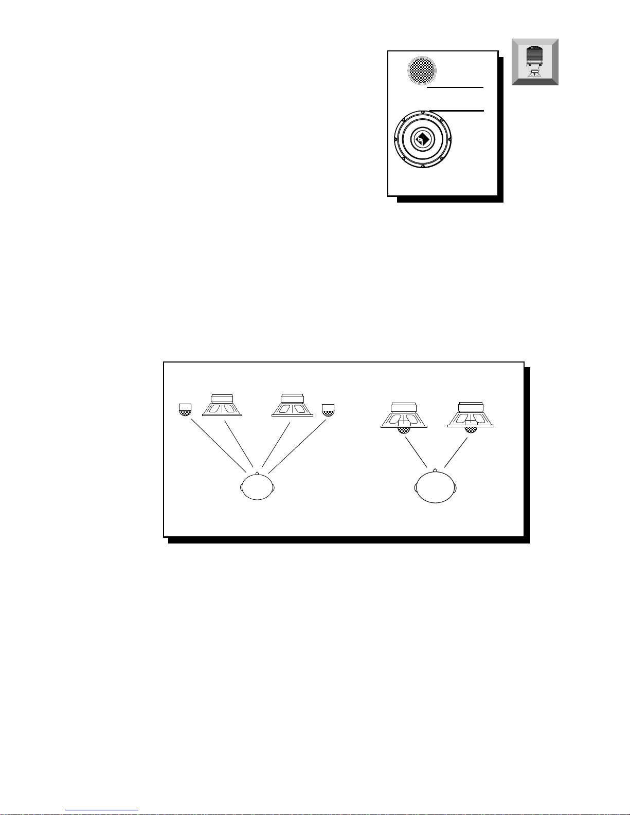
Placing the Punch Splits Speakers
A solid front stage with a good image is one of the most difficult tasks to
achieveinavehicle.Nocarhastheoptimumlisteningenvironment.This
makes proper sound staging very difficult to accomplish. Most speakers
tendtobeplaced wheretheywillfiteasily, asopposedtowherethey can
performthebest
ThemountinglocationofyourPunchSplitsspeakerswill
haveagreateffectonthesoundqualityofyourstereosystem.Thespecial
care taken to place the Punch Splits speakers, will yield many hours of
listeningenjoymentinreturn.Severalimportantrecommendationsshould
be followed.