Rockford Systems, LLC
Call: 1-800-922-7533 5
SECTION 1—IN GENERAL
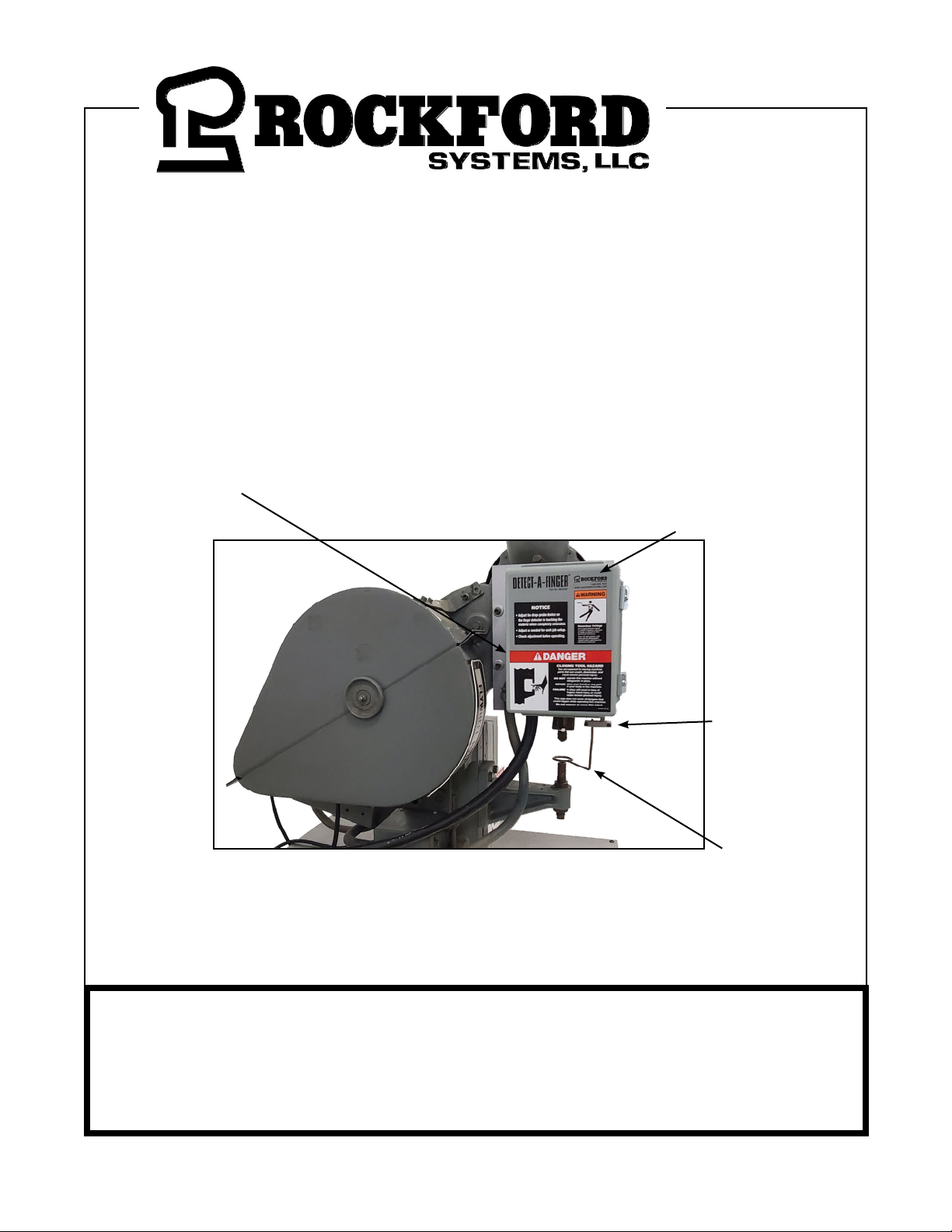
Detect-A-Finger™ Gen II Drop Probe Device - Riveter
Do Not Operate This Machine
Until You Read and Understand the
Following Safety Precautions.
Never operate this machine until you understand that this
machine is dangerous and if you place your hands, or any
part of your body in this machine it could result in the loss of
fingers, limbs or even death.
Never operate this machine without the use of a guard or
safety device that will always protect you from bodily injury.
Never use a foot switch to operate this machine unless
a point-of-operation guard or device is provided and
properly maintained.
Never “ride” the foot pedal or foot switch. Never rest your
foot on top of the foot pedal or inside the foot switch. Always
remove your foot completely from the foot pedal or foot
switch after each cycle and any time you are not intending
to trip the machine.
Always use hand tools for feeding or retrieving material
from the point of operation or any other hazardous part of the
machine. Never reach through or into die area for any reason.
Never operate this machine unless you feel you have been
fully trained and have received and understand all operating
instructions. Make sure you know how the machine works
and how it is controlled.
Never operate this machine until you test the machine with its
guard or safety device before you start or restart production.
Do not begin operating the machine unless you are sure the
safeguarding is adjusted properly and working correctly. If you
are not sure call your supervisor.
Never operate this machine if it is not working properly or if
you notice any unusual noise or change in the performance
of the machine. Stop operating the machine immediately and
advise your supervisor.
Never operate this machine with pullbacks unless they are
adjusted properly for you. Have your supervisor show you
manually that when the ram descends the pullbacks will
pull your fingers clear of any pinch points. Always wear your
wristlets properly and securely.
Never operate this machine with pullbacks without reading
and understanding the instructions. Instructions must be kept
with the pullback device at all times and made available to
you. Obtain, read and follow these instructions.
Never operate this machine unless two-hand trip, two-hand
control or presence sensing device are installed correctly and
at the proper safety distance. Consult your supervisor should
you have any questions regarding the proper safety distance.
Never tamper with, rewire or bypass any control, component
or safeguard on this machine.
Always wear safety glasses, ear protection and any other
personal protection equipment needed when operating this
machine.
Be sure all persons are clear of the machine before it is
cycled, especially when multiple operators are present. Do
not operate machine unless you and every operator and/or
helper are protected from injury by a guard or safety device.
Always stay alert (don’t daydream) and never operate this
machine while under the influence of alcohol or any other drug
including prescription medications.
Maintenance and Die Set-Up Personnel: Never work on
this machine unless power is off, flywheel is at rest, safety
blocks are used between dies, ram and bolster plate and
all energy (electrical, air, hydraulic, etc.) are in a zero state.
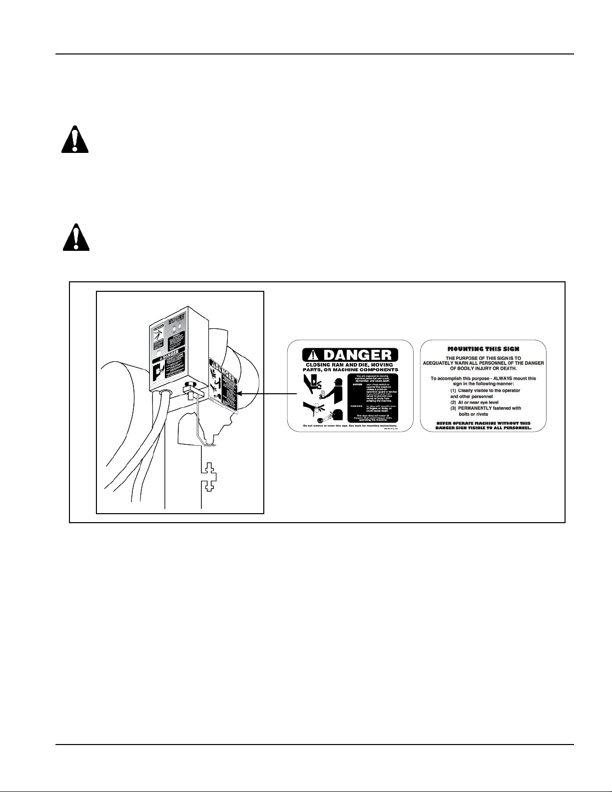
NOTICE TO EMPLOYER: A copy of this “Operator Safety Precautions” must be given to all operators (including die set-
up people, maintenance personnel and supervisors) of this machine. A copy should also be hung on the machine
readily accessible and visible to the operator. Additional copies of this precaution are available upon request.
Just call or write.
IMPORTANT: Where a language barrier or insufficient schooling would prevent a person from reading and understand-
ing the contents of this Operator Safety Precaution, you should either translate this information or have it read or
interpreted to the person, with assurance that it is understood.
THIS PRECAUTION MUST BE REVIEWED DAILY.
(Continued on next page.)
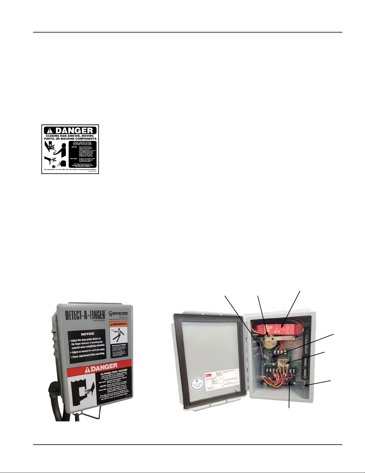
Accompanying this equipment is an 8-1/2”
x 11” operator safety precaution pamphlet,
Part No. KSC000, for anyone operating the
machine where this equipment will be
installed. This precaution pamphlet is to be
given to all operators, including setup people,
maintenance personnel and supervisors.
This pamphlet should also be attached to
the machine, readily accessible and visible
to the operator. (A hole in the corner of this
precaution pamphlet is provided for attaching
purposes.) Additional copies of this precaution
are available. Please call, e-mail, write, fax, or
use the order form found on a later page in
this manual.
When a language barrier or insufficient
education prevents a person from reading or
understanding the contents of this operator
safety precaution pamphlet, you should either
translate this information or have it read or
interpreted to the person. Make sure that
the person understands the information. To
order this pamphlet in Spanish, use Part No.
KSC000S; in French, use Part No. KSC000F.
This precaution pamphlet must be reviewed daily.
Operator Safety Precaution Pamphlet (Attachment for machine operators)
Front
1
2
3
4
5
6
7
8
10
11
16
15
14
13
12
9
Back