Rockwell Automation Allen-Bradley ASEM 6300 User manual

User Manual Original Instructions
ASEM 6300 RVL Receiver and
RVL Transmitter
Catalog Numbers 6300V-RVLDV-RX, 6300V-RVLDV-TX

2Rockwell Automation Publication 6300V-UM001B-EN-P - October 2023
ASEM 6300 RVL Receiver and RVL Transmitter User Manual
Important User Information
Read this document and the documents listed in the Additional Resources section about installation, configuration, and operation of this
equipment before you install, configure, operate, or maintain this product. Users are required to familiarize themselves with installation and
wiring instructions in addition to requirements of all applicable codes, laws, and standards.
Activities including installation, adjustments, putting into service, use, assembly, disassembly, and maintenance are required to be carried
out by suitably trained personnel in accordance with applicable code of practice.
If this equipment is used in a manner not specified by the manufacturer, the protection provided by the equipment may be impaired.
In no event will Rockwell Automation, Inc. be responsible or liable for indirect or consequential damages resulting from the use or application
of this equipment.
The examples and diagrams in this manual are included solely for illustrative purposes. Because of the many variables and requirements
associated with any particular installation, Rockwell Automation, Inc. cannot assume responsibility or liability for actual use based on the
examples and diagrams.
No patent liability is assumed by Rockwell Automation, Inc. with respect to use of information, circuits, equipment, or software described in
this manual.
Reproduction of the contents of this manual, in whole or in part, without written permission of Rockwell Automation, Inc., is prohibited.
Throughout this manual, when necessary, we use notes to make you aware of safety considerations.
These labels may also be on or inside the equipment to provide specific precautions.
The following icon may appear in the text of this document.
WARNING: Identifies information about practices or circumstances that can cause an explosion in a hazardous environment,
which may lead to personal injury or death, property damage, or economic loss.
ATTENTION: Identifies information about practices or circumstances that can lead to personal injury or death, property
damage, or economic loss. Attentions help you identify a hazard, avoid a hazard, and recognize the consequence.
IMPORTANT Identifies information that is critical for successful application and understanding of the product.
SHOCK HAZARD: Labels may be on or inside the equipment, for example, a drive or motor, to alert people that dangerous
voltage may be present.
BURN HAZARD: Labels may be on or inside the equipment, for example, a drive or motor, to alert people that surfaces may
reach dangerous temperatures.
ARC FLASH HAZARD: Labels may be on or inside the equipment, for example, a motor control center, to alert people to
potential Arc Flash. Arc Flash will cause severe injury or death. Wear proper Personal Protective Equipment (PPE). Follow ALL
Regulatory requirements for safe work practices and for Personal Protective Equipment (PPE).
Identifies information that is useful and can help to make a process easier to do or easier to understand.

Rockwell Automation Publication 6300V-UM001B-EN-P - October 2023 3
Table of Contents
Preface
About This Publication . . . . . . . . . . . . . . . . . . . . . . . . . . . . . . . . . . . . . . . . . . . . . . . . . . . . . . 5
Summary of Changes . . . . . . . . . . . . . . . . . . . . . . . . . . . . . . . . . . . . . . . . . . . . . . . . . . . . . . . 5
Catalog Numbers . . . . . . . . . . . . . . . . . . . . . . . . . . . . . . . . . . . . . . . . . . . . . . . . . . . . . . . . . . 5
Compliance . . . . . . . . . . . . . . . . . . . . . . . . . . . . . . . . . . . . . . . . . . . . . . . . . . . . . . . . . . . . . . . 5
UL/cUL Mark Compliance. . . . . . . . . . . . . . . . . . . . . . . . . . . . . . . . . . . . . . . . . . . . . . . . 5
European Union Directive and UKCA Compliance . . . . . . . . . . . . . . . . . . . . . . . . . . . . 5
Additional Resources . . . . . . . . . . . . . . . . . . . . . . . . . . . . . . . . . . . . . . . . . . . . . . . . . . . . . . . 6
Chapter 1
Overview Schema . . . . . . . . . . . . . . . . . . . . . . . . . . . . . . . . . . . . . . . . . . . . . . . . . . . . . . . . . . . . . . . . . . 7
Approximate Dimensions. . . . . . . . . . . . . . . . . . . . . . . . . . . . . . . . . . . . . . . . . . . . . . . . . . . . 8
Peripheral Connections . . . . . . . . . . . . . . . . . . . . . . . . . . . . . . . . . . . . . . . . . . . . . . . . . . . . . 8
LED Status Indicators. . . . . . . . . . . . . . . . . . . . . . . . . . . . . . . . . . . . . . . . . . . . . . . . . . . . . . . 9
Accessories . . . . . . . . . . . . . . . . . . . . . . . . . . . . . . . . . . . . . . . . . . . . . . . . . . . . . . . . . . . . . . . 9
Chapter 2
Prepare for Installation Unpack the Product . . . . . . . . . . . . . . . . . . . . . . . . . . . . . . . . . . . . . . . . . . . . . . . . . . . . . . . 11
Installation Precautions. . . . . . . . . . . . . . . . . . . . . . . . . . . . . . . . . . . . . . . . . . . . . . . . . . . . 11
Hazardous Locations . . . . . . . . . . . . . . . . . . . . . . . . . . . . . . . . . . . . . . . . . . . . . . . . . . 11
Installation Requirements . . . . . . . . . . . . . . . . . . . . . . . . . . . . . . . . . . . . . . . . . . . . . . . . . . 12
Installation Site Guidelines . . . . . . . . . . . . . . . . . . . . . . . . . . . . . . . . . . . . . . . . . . . . . . . . . 12
Mounting Requirements . . . . . . . . . . . . . . . . . . . . . . . . . . . . . . . . . . . . . . . . . . . . . . . . 12
DC Power Supply Requirements . . . . . . . . . . . . . . . . . . . . . . . . . . . . . . . . . . . . . . . . . 12
Required Tools and Hardware . . . . . . . . . . . . . . . . . . . . . . . . . . . . . . . . . . . . . . . . . . . 13
Chapter 3
Installation Mount . . . . . . . . . . . . . . . . . . . . . . . . . . . . . . . . . . . . . . . . . . . . . . . . . . . . . . . . . . . . . . . . . . . 15
Attach the Bracket Kit . . . . . . . . . . . . . . . . . . . . . . . . . . . . . . . . . . . . . . . . . . . . . . . . . 15
Secure your RVL Receiver And/or RVL Transmitter . . . . . . . . . . . . . . . . . . . . . . . . . 16
Assemble the DC Terminal Block Kit. . . . . . . . . . . . . . . . . . . . . . . . . . . . . . . . . . . . . . . . . . 16
Install the Ground Wire. . . . . . . . . . . . . . . . . . . . . . . . . . . . . . . . . . . . . . . . . . . . . . . . . . . . . 17
Connect Peripheral Cables . . . . . . . . . . . . . . . . . . . . . . . . . . . . . . . . . . . . . . . . . . . . . . . . . 18
Chapter 4
Operation Required Basic Knowledge . . . . . . . . . . . . . . . . . . . . . . . . . . . . . . . . . . . . . . . . . . . . . . . . . 19
Proper Use of the Product. . . . . . . . . . . . . . . . . . . . . . . . . . . . . . . . . . . . . . . . . . . . . . . . . . 19
Apply Power to the RVL Device . . . . . . . . . . . . . . . . . . . . . . . . . . . . . . . . . . . . . . . . . . . . . . 20

4Rockwell Automation Publication 6300V-UM001B-EN-P - October 2023
Table of Contents
Appendix A
Technical Specifications RVL Receiver . . . . . . . . . . . . . . . . . . . . . . . . . . . . . . . . . . . . . . . . . . . . . . . . . . . . . . . . . . . . . 21
Approximate Dimensions . . . . . . . . . . . . . . . . . . . . . . . . . . . . . . . . . . . . . . . . . . . . . . . 21
Specifications . . . . . . . . . . . . . . . . . . . . . . . . . . . . . . . . . . . . . . . . . . . . . . . . . . . . . . . . 23
RVL Transmitter . . . . . . . . . . . . . . . . . . . . . . . . . . . . . . . . . . . . . . . . . . . . . . . . . . . . . . . . . . 24
Approximate Dimensions . . . . . . . . . . . . . . . . . . . . . . . . . . . . . . . . . . . . . . . . . . . . . . . 24
Specifications . . . . . . . . . . . . . . . . . . . . . . . . . . . . . . . . . . . . . . . . . . . . . . . . . . . . . . . . 26
Connector Pinout . . . . . . . . . . . . . . . . . . . . . . . . . . . . . . . . . . . . . . . . . . . . . . . . . . . . . . . . . 27
Cables. . . . . . . . . . . . . . . . . . . . . . . . . . . . . . . . . . . . . . . . . . . . . . . . . . . . . . . . . . . . . . . . . . . 28

Rockwell Automation Publication 6300V-UM001B-EN-P - October 2023 5
Preface
About This Publication This publication provides guidance on how to operate your ASEM™ remote video link (RVL)
devices, RVL receiver and RVL transmitter, when connected to an industrial PC.
See Schema on page 7 for various configurations.
A general knowledge of automation technology is required to understand and follow the
instructions in this publication.
This user manual contains information based on the requirements that are defined by
DIN EN 62079 for mechanical engineering documentation. These operating instructions are
intended for end users, commissioning engineers, and maintenance personnel.
Summary of Changes This publication contains the following new or updated information. This list includes
substantive updates only and is not intended to reflect all changes.
Catalog Numbers This publication is applicable to these RVL receiver and RVL transmitter catalog numbers. For
your catalog number, see the product label on the side of your product.
Compliance UL/cUL Mark Compliance
Equipment with the UL/cUL mark complies with the requirements of UL 61010-1,
UL 61010-2-201, CSA C22.2 No. 61010-1, and CSA C22.2 No. 61010-2-201. A copy of the certificate
of compliance is available at rok.auto/certifications.
European Union Directive and UKCA Compliance
This equipment meets the European Union Directive and UK requirements when installed
within the European Union or EEA regions and have the CE marking. A copy of the declaration
of the conformity is available at rok.auto/certifications.
Topic Page
Removed obsolete catalog number 6300V-RVLDV-RXTX Front Cover
Removed obsolete catalog number 6300V-RVLDV-RXTX from Catalog Numbers table 5
Product Description Catalog Number
RVL Receiver 6300V-RVLDV-RX
RVL Transmitter 6300V-RVLDV-TX
ATTENTION: This equipment is intended to operate in an industrial or
control room environment, which uses some form of power isolation from
the public low-voltage mains. Some computer configurations cannot comply
with the EN 61000-3-2 Harmonic Emissions standard as specified by the EMC
Directive of the European Union. All I/O cables must be used only indoors.

6Rockwell Automation Publication 6300V-UM001B-EN-P - October 2023
Preface
Additional Resources These documents contain additional information concerning related products from Rockwell
Automation. You can view or download publications at rok.auto/literature.
ASREM
Resource Description
ASEM 6300B Box PC and 6300T Thin Clients User Manual,
publication 6300B-UM001
Provides details on how to configure, operate, and troubleshoot the ASEM 6300B book mount box PCs
and 6300T book mount box thin clients.
ASEM 6300M Panel Monitor User Manual, publication 6300M-UM001 Provides details on how to configure, operate, and troubleshoot the ASEM 6300M panel monitors.
ASEM 6300PA Panel PC User Manual, publication 6300-UM002 Provides details on how to configure, operate, and troubleshoot the ASEM 6300PA panel PCs.
ASEM 6300 Industrial Computer and Monitor Specifications
Technical Data, publication 6300-TD001 Provides technical specifications for ASEM 6300 industrial computers and monitors.
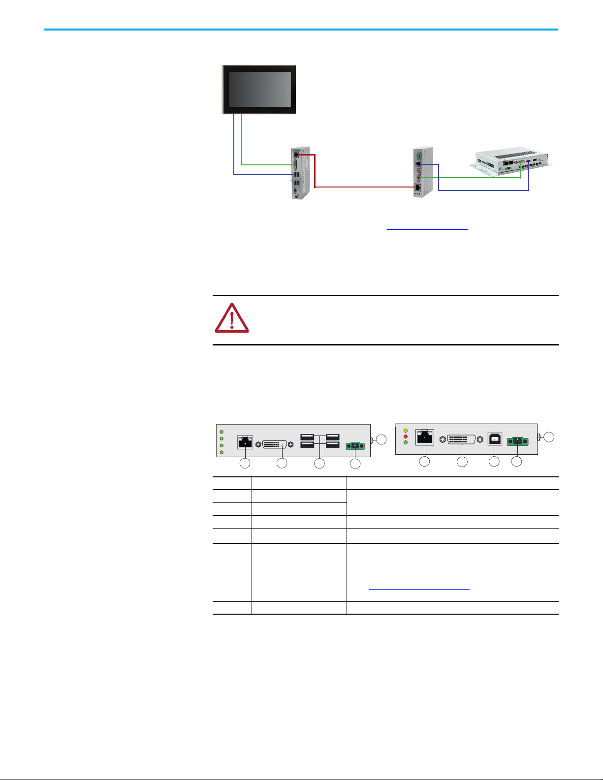
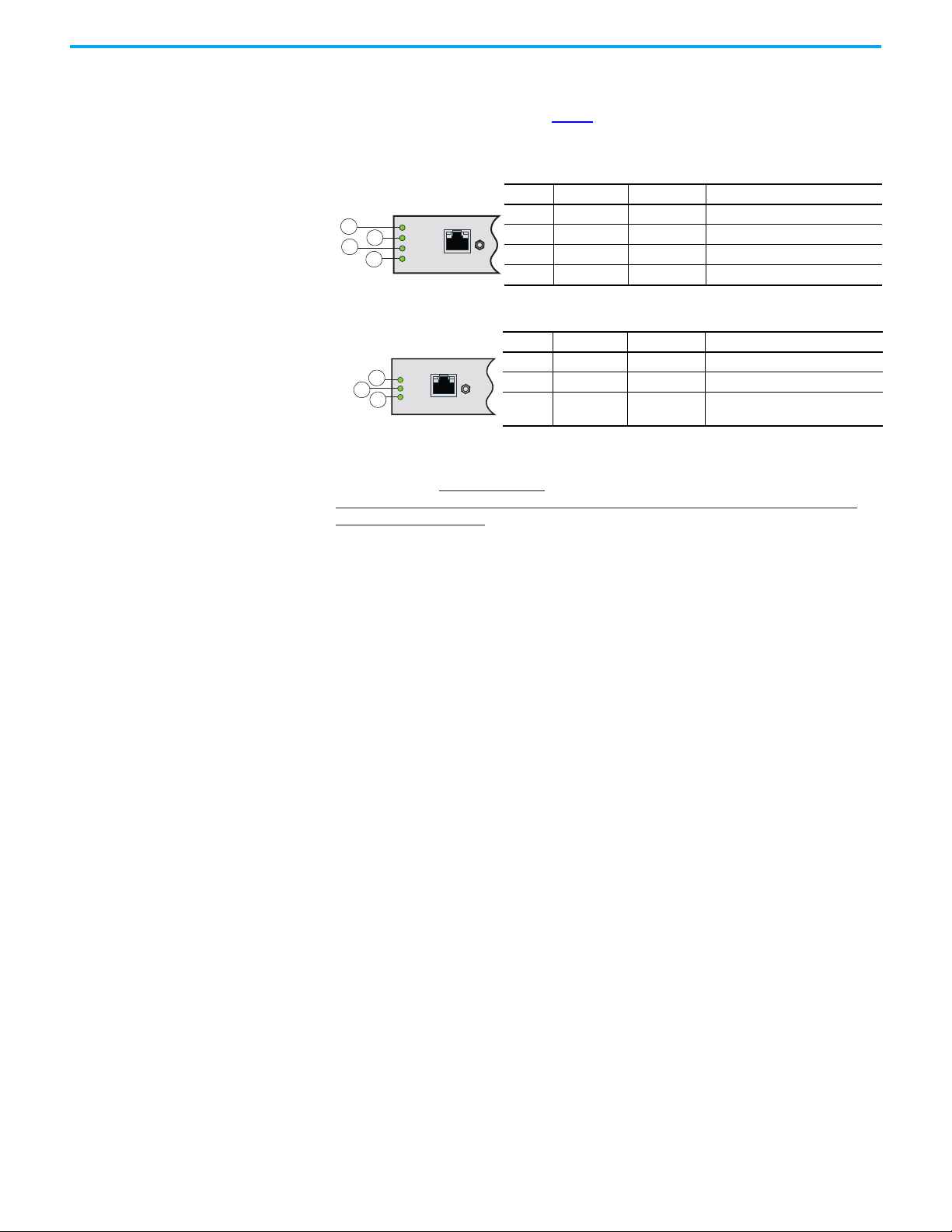
ASEM RVL Receiver, publication 6300V-IN004 Provides installation instructions to mount and connect your ASEM RVL receiver to other components.
ASEM RVL Transmitter, publication 6300V-IN005 Provides installation instructions to mount and connect your ASEM RVL transmitter to other
components.
ASEM 6300V Industrial Computer and Monitor Accessories,
publication 6300V-PC001 Provides product information of accessories for 6300 industrial computers and monitors.
American Standards, Configurations, and Ratings:
Introduction to Motor Circuit Design, publication IC-AT001 Provides an overview of American motor circuit design based on methods that are outlined in the NEC.
EtherNet/IP™ Network Devices User Manual, ENET-UM006 Describes how to configure and use EtherNet/IP devices to communicate on the EtherNet/IP network.
Ethernet Reference Manual, ENET-RM002 Describes basic Ethernet concepts, infrastructure components, and infrastructure features.
Industrial Automation Wiring and Grounding Guidelines, publication
1770-4.1 Provides general guidelines for installing a Rockwell Automation® industrial system.
Industrial Components Preventive Maintenance, Enclosures, and
Contact Ratings Specifications, publication IC-TD002 Provides a quick reference tool for Allen-Bradley® industrial automation controls and assemblies.
Product Certifications website, rok.auto/certifications. Provides declarations of conformity, certificates, and other certification details.
System Security Design Guidelines Reference Manual, publication
SECURE-RM001
Provides guidance on how to conduct security assessments, implement Rockwell Automation
products in a secure system, harden the control system, manage user access, and dispose of
equipment.
UL Standards Listing for Industrial Control Products,
publication CMPNTS-SR002
Assists original equipment manufacturers (OEMs) with construction of panels, to help achieve
conformity to the requirements of Underwriters Laboratories.
Safety Guidelines for the Application, Installation, and Maintenance
of Solid-state Control, publication SGI-1.1
Designed to harmonize with NEMA Standards Publication No. ICS 1.1-1987 and provides general
guidelines for the application, installation, and maintenance of solid-state control in the form of
individual devices or packaged assemblies that incorporate solid-state components.

Rockwell Automation Publication 6300V-UM001B-EN-P - October 2023 7
Chapter 1
Overview
The ASEM™ remote video link (RVL) receiver and RVL transmitter, provide long-distance video
connections up to 100 meters (328 ft) between industrial monitors and industrial PCs via an
RVL cable. There are additional connections available to include both DVI-D and USB 2.0
signals.
Schema There are several ways to lay out your RVL receiver and/or RVL transmitter with other
industrial components to accommodate your needs.
Figure 1 - Industrial Monitor with Integrated Receiver > Industrial PC with Integrated Transmitter
Figure 2 - Industrial Monitor with Integrated Receiver > External RVL Transmitter > Industrial PC
Figure 3 - Industrial Monitor > External RVL Receiver > Industrial PC with Integrated Transmitter
Industrial Monitor
with Integrated RVL Receiver
RVL Cable
100 m (328 ft) Maximum Length
Industrial PC
with Integrated Transmitter
Industrial Monitor
with Integrated RVL Receiver RVL Transmitter
6300V-RVLDV-TX Industrial PC
USB 2.0 Cable
DVI Cable
RVL Cable
100 m (328 ft) Maximum Length
Industrial Monitor
RVL Receiver
6300V-RVLDV-RX
RVL Cable
100 m (328 ft) Maximum Length
USB 2.0 Cable
Industrial PC
with Integrated Transmitter
DVI Cable

8Rockwell Automation Publication 6300V-UM001B-EN-P - October 2023
Chapter 1 Overview
Figure 4 - Industrial Monitor > External RVL Receiver > External RVL Transmitter > Industrial PC
Approximate Dimensions For information about product dimensions, see Appendix A on page 21. Dimensions are not
intended to be used for manufacturing purposes.
Peripheral Connections There are several I/O ports easily accessible on the front of the RVL receiver and/or RVL
transmitter. These I/O ports accommodate specific cable types.
The following table identifies the input/output (I/O) ports on the front of your RVL receiver
and/or RVL transmitter.
Industrial Monitor
RVL Receiver
6300V-RVLDV-RX
RVL Cable
100 m (328 ft) Maximum Length
RVL Transmitter
6300V-RVLDV-TX Industrial PC
USB 2.0 Cable
DVI Cable
USB 2.0 Cable
DVI Cable
WARNING: USB 2.0 peripheral connections cannot be used in hazardous
locations. Only connect a shielded USB 2.0 cable for initial setup and
maintenance. Disconnect the shielded USB 2.0 cable once the initial setup or
maintenance is completed.
Table 1 - I/O Port Locations and Ground Screw
Note No. Component/Cable Type Required Attribute
1A RVL In Shielded cable, 100 m (328 ft) maximum length
1B RVL Out
2 DVI-D Output Shielded cable
3USB 2.0 (1)
(1) The USB ports are not for use in hazardous locations. Only use the USB ports for initial setup and maintenance.
Shielded cable
4 24V DC Power Connection
• A safety extra low voltage (SELV) power supply is required.
The internal power supply is protected against reverse polarity.
• To minimize ground loop currents and noise, we recommend that
your DC powered RVL receiver uses only one grounded connection.
See Install the Ground Wire on page 17 for the ground connection
on these models.
5 Ground (Earth) Screw —
1A 24
3
55
4
3
2
1B
Front View Front View
RVL Receiver RVL Transmitter

Rockwell Automation Publication 6300V-UM001B-EN-P - October 2023 9
Chapter 1 Overview
LED Status Indicators Once all peripheral connections have been made and all components of your schema have
been powered on, light emitting diode (LED) status indicators illuminate on the front of your
RVL receiver and/or RVL transmitter. Table 2 provides the location and description of each
LED status indicator.
Accessories Various accessories are available for an RVL receiver and RVL transmitter. A partial list of
cables is listed in Cables on page 28. You can view the full list of accessories at:
https://www.rockwellautomation.com/en-us/products/hardware/allen-bradley/industrial-
computers-monitors.html.
Table 2 - LED Status Indicators: RVL Receiver
Note No. LED Indicator Status Description
1 Link Green linked to the RVL transmitter
2 Run Flashing Green operating correctly
3 Power Green receiving power
4 Video Green receiving video signal output
Table 3 - LED Status Indicators: RVL Transmitter
Note No. LED Indicator Status RVL Transmitter is:
1 Link Green linked to the RVL receiver
2 Run Flashing Green operating correctly
3 Power Green transmitting power
12
34
RVL Receiver
1
23
RVL Transmitter

10 Rockwell Automation Publication 6300V-UM001B-EN-P - October 2023
Chapter 1 Overview
Notes:

Rockwell Automation Publication 6300V-UM001B-EN-P - October 2023 11
Chapter 2
Prepare for Installation
Unpack the Product Before you unpack your remote video link (RVL) receiver and RVL transmitter, inspect the
shipping carton for damage. If damage is visible, immediately contact the shipper and request
assistance. Otherwise, proceed with unpacking.
The following components are parts are shipped along with your RVL receiver and/or RVL
transmitter.
.
Installation Precautions Hazardous Locations
Keep the original packing material in case your product must be returned for
repair or transported to another location.
Table 4 - Package Contents
RVL Receiver,
Cat. No. 6300V-RVLDV-RX
• DC Terminal Block Kit
• Installation Instructions
•Mountingkits:
– Book mount kit: bracket (quantity 1) and screws (quantity 2)
– Wall mount kit: brackets (quantity 2) and screws (quantity 4)
– DIN rail mount kit: rail hook (quantity 1) and screws (quantity 2)
RVL Transmitter,
Cat. No. 6300V-RVLDV-RX
• DC Terminal Block Kit
• Installation Instructions
•Mountingkits:
– Book mount kit: bracket (quantity 1) and screws (quantity 2)
– Wall mount kit: brackets (quantity 2) and screws (quantity 4)
– DIN rail mount kit: rail hook (quantity 1) and screws (quantity 2
WARNING: This RVL receiver is:
• suitable for use in CLASS I, DIVISION 2, GROUPS A, B, and D Hazardous Locations
or Non-hazardous Locations only.
• considered open equipment, which means that it can only be integrated in
housings or cabinets where the product can only be accessed by authorized
personnel using a key or tool.
WARNING: This RVL transmitter is:
• suitable for use in CLASS I, DIVISION 2, GROUPS A, B, and D Hazardous Locations
or Non-hazardous Locations only.
• considered open equipment, which means that it can only be integrated in
housings or cabinets where the product can only be accessed by authorized
personnel using a key or tool.

12 Rockwell Automation Publication 6300V-UM001B-EN-P - October 2023
Chapter 2 Prepare for Installation
Installation Requirements Installation Site Guidelines
Follow these installation site guidelines to make sure that your RVL receiver and/or RVL
transmitter provides service with excellent reliability.
• When choosing the installation site, consider the following:
- The site must have sufficient power.
- The site must be indoors and not exposed to direct sunlight.
• The maximum operating ambient temperature of your RVL receiver and/or transmitter
is 50 °C (122 °F).
- Measure the ambient temperature 5 cm (2 in.) away from all cooling openings.
- Make sure all cooling openings/grids are not obstructed to confirm proper airflow.
- Store in a surrounding air temperature range of -5…+60 °C (23…140 °F).
- The relative humidity (RH) of the ambient air must be 80% non-condensing when
your RVL receiver is operating or being stored.
• When planning the layout and connections of your RVL receiver:
- For electromagnetic compatibility (EMC), place the cables away from the sources of
electric noise (such as power cables, high-voltage power sources, transformers,
electric welders, or radio frequency (RF) sources) that could compromise the quality
of the signal.
- Do not place the RVL cable together with power cables unless an adequate insulation
class is provided.
- The chassis of your RVL receiver and/or RVL product must be connected to ground
via the ground screw.
- Consider the placement of required components and the maximum length of the
cables to connect your RVL receiver and/or RVL transmitter to other components.
See Required Tools and Hardware.
Mounting Requirements
DC Power Supply Requirements
• Your DC powered RVL receiver and/or RVL transmitter requires a safety extra low
voltage (SELV) power supply. The internal power supply is protected against reverse
polarity.
• To minimize ground loop currents and noise, we recommend that your DC powered RVL
transmitter uses only one grounded connection. See Install the Ground Wire on page 17
for the ground connection on these models.
• Tighten the screws on top of the DC terminal block to secure the DC power wires to the
torque value in Table 7 on page 16.
IMPORTANT If you are installing your RVL device in an environment where vibration
is present, it must be secured to a shelf or wall using one of the
mounting kits (supplied). DIN rail mounting is not recommended for
high shock and vibration environments.
We recommend that the computer circuit be supplied with its own disconnect. Use
an uninterruptible power supply (UPS) to help protect against unexpected power
failure or power surges.

Rockwell Automation Publication 6300V-UM001B-EN-P - October 2023 13
Chapter 2 Prepare for Installation
Required Tools and Hardware
The following hardware and tools are required to complete your installation.
Table 5 - Required Equipment for RVL Receiver
Components
• Industrial monitor
• For receiver installation: Industrial PC with integrated transmitter or RVL transmitter
(Cat. No. 6300V-RVLDV-TX) and Industrial PC
• DIN Rail (for DIN rail-mount installation only)
• 24V DC (input voltage 18…32V DC) power supply (1)
(1) The power supply must:
(a) satisfy the requirements of a safe extra low voltage (SELV) in accordance with IEC/EN/DIN EN/UL60950-1 and
(b) fulfill the requirements NEC Class 2 LPS in accordance with IEC/EN/DIN EN/UL60950-1.
Connect the system with a cable cross-section of 0.75…1.5 mm2(from 18…AWG16) suitable in a minimum of 75 °C (167 °F).
Cables
• DVI cable, 11 m (36 ft) maximum length (2)
• USB 2.0 cable, 11 m (36 ft) maximum length (2)
• RVL (Cat. 5E/Cat. 6 A connection) cable, 100 m (328 ft) maximum length, quantity 1
(2) Two cables are required if your RVL receiver installation requires a separate RVL transmitter (6300V-RVLDV-TX).
Tools
• For wall mount, shelf mount, or DIN rail attachment:
– Drill and 4 mm (0.16 in.) drill bit
– #2 Phillips screwdriver
– M4x20 stainless-steel screws, quantity 4
• For DC power connector assembly and ground wire installation:
– 2.5 mm (.10 in.) hex screwdriver
– Wire stripper, cutter, and crimper tool
– Cutting pliers
– Safety glasses
Table 6 - Required Equipment for RVL Transmitter
Components
• Industrial monitor with integrated RVL receiver or integrated monitor with external RVL Receiver
(Cat. No. 6300V-RVLDV-RX)
• Industrial PC
• DIN rail (for DIN rail-mount installation only)
• 24V DC (input voltage 18…32V DC) power supply (1)
(1) The power supply must:
(a) satisfy the requirements of a SELV in accordance with IEC/EN/DIN EN/UL60950-1 and
(b) fulfill the requirements NEC Class 2 LPS in accordance with IEC/EN/DIN EN/UL60950-1.
Connect the system with a cable cross-section of 0.75…1.5 mm2(from 18…16 AWG) suitable in a minimum of 75 °C (167 °F).
Cables
• DVI cable, 11 m (36 ft) maximum length (2)
• USB 2.0 cable, 11 m (36 ft) maximum length (2)
• RVL (Cat. 5E/Cat. 6 A connection) cable, 100 m (328 ft) maximum length, quantity 1
(2) Two cables are required if your installation requires a separate RVL receiver (6300V-RVLDV-RX).
Tools
• For wall mount, shelf mount, or DIN rail attachment:
– Drill and 4 mm drill bit
– #2 Phillips screwdriver
– M4x20 stainless steel screws, quantity 4
• For DC power connector assembly and ground wire installation:
– 2.5 mm hex screwdriver
– Wire stripper, cutter, and crimper tool
– Cutting pliers
– Safety glasses

14 Rockwell Automation Publication 6300V-UM001B-EN-P - October 2023
Chapter 2 Prepare for Installation
Notes:

Rockwell Automation Publication 6300V-UM001B-EN-P - October 2023 15
Chapter 3
Installation
Mount
Attach the Bracket Kit
A book mount bracket kit, wall mount bracket kit, and a DIN rail mount kit for bottom mount or
back mount installation is supplied with your RVL receiver and RVL transmitter.
Figure 5 - Mounting Bracket Kits and Attachment
IMPORTANT If you are installing RVL devices in an environment where vibration is
present, it must be secured to a shelf or wall using one of the mounting
kits (supplied). DIN rail mounting is not recommended for high shock
and vibration environments. If vibration is not present and you are not
mounting your RVL devices to a wall, shelf, or DIN rail, proceed to
Connect Peripheral Cables on page 18.
Book Mount Bracket Installation
Bracket
Bracket
Attachment
Screws
Wall Mount Bracket Installation
View of Unit from Bottom
View of Unit
from Side
Screws Screws
Bracket Bracket
Bracket
Attachment
Bracket
Attachment
DIN Rail Bottom Mount Installation
View of Unit from Bottom
Screws
Hook Attachment
DIN Rail
Hook
View of Unit
from Side
DIN Rail
Hook Profile
Screws
Hook
Attachment
View of Unit from Back
DIN Rail
Hook
DIN Rail Hook
Profile
View of Unit from Top
DIN Rail Back Mount

16 Rockwell Automation Publication 6300V-UM001B-EN-P - October 2023
Chapter 3 Installation
1. See Figure 5 to identify the correct mounting holes for your selected mounting kit.
2. For each RVL device: Use a 2.5 mm hex screwdriver to tighten the screws (supplied) to
secure one or more brackets or DIN rail hook to your RVL receiver.
3. Torque the screws to a value of 1…1.2 N•m (8.85…10.62 ft•lb).
Secure your RVL Receiver And/or RVL Transmitter
1. Check that your RVL receiver and/or RVL transmitter is level and square.
2. Mark and drill pilot holes in the wall or shelf.
3. For book mount or wall mount installation:
- Insert the M4x20 mounting screws (not provided) through the mounting holes of the
bracket and into the pilot holes on the wall or shelf, then tighten the mounting
screws.
For DIN rail bottom mount or DIN rail back mount installation:
- Attach the DIN rail hook to the DIN rail (not provided).
Assemble the DC Terminal
Block Kit
The connector assembly provides strain relief for the DC power wires by reducing their
movement. Follow the instruction below to assemble and attach the DC terminal block kit.
Figure 6 - DC Terminal Block Assembly Steps
1. Open the DC terminal block (supplied) (A in Figure 6).
2. Insert the cable tie through the slots of the appropriate connector clamp (B in Figure 6).
3. Strip 7 mm (0.28 in.) from the end of each DC power wire.
4. Insert each stripped end into the DC terminal block as shown in Table 7.
5. Tighten the screws on top of the DC terminal block to secure the DC power wires to the
torque value in Table 7 on page 16.
IMPORTANT Do not overtighten the screws. Overtightening can cause
damage.
IMPORTANT The DC terminal block in the photos is only for illustrative purposes.
Your DC terminal block can differ in size, shape, and color to what is
shown in the photos.
Table 7 - DC Terminal Block Connection Specifications
Note No. Description Attribute
1DC+ (24V DC nominal)
recommended power wire size 1.5 mm2
(16 AWG)
2DC- (0V DC)
recommended power wire size 1.5 mm2
(16 AWG)
3 Stripped wire length 7 mm
(0.275 in.)
4Torque range to secure
DC power wires 0.22...0.25 N•m
(0.16...0.18 lb•ft)
5Torque value to reinstall DC
terminal block to computer 0.3 N•m
(0.22 lb•ft)
IMPORTANT DC power wires must be made of stranded copper and sized
according to Table 7 on page 16.
1
2
3
34
4
5
5
ABCDEFG

Rockwell Automation Publication 6300V-UM001B-EN-P - October 2023 17
Chapter 3 Installation
6. Slide the connector half with the attached cable tie onto the end of the DC terminal
block (C in Figure 6 on page 16).
7. Tighten the cable tie so it is snug against the terminal wires.
8. Use cutting pliers to cut the excess cable tie (D in Figure 6 on page 16).
9. Install the white label supplied with the kit (E in Figure 6 on page 16).
10. Align and install the other connector clamp half to complete the assembly (F in
Figure 6).
11. Reconnect the DC terminal block with the connector assembly (G in Figure 6 on page 16)
to your RVL receiver and/or RVL transmitter.
12. Torque the DC terminal block flange screws to the values in Table 7 on page 16.
Install the Ground Wire
1. Be sure that the main power switch or breaker is still turned off.
2. Remove the supplied nut, eyelet terminal, and washers from the ground screw on the
side of your RVL receiver and/or RVL transmitter.
See Table 1 on page 8 for the ground screw location.
3. Attach a 2.50 mm2(14 AWG) or larger external wire to the eyelet terminal.
4. Strip 5 mm (0.20 in.) from the covering at the end of the grounding wire.
5. Insert the stripped end of the grounding wire into the open end of the eyelet terminal,
and crimp it securely to the wire.
6. Install the ground wire and washers to the ground screw in the following sequence:
7. Reinstall the nut to the chassis of your RVL receiver and/or RVL transmitter.
8. Route and connect the loose end of the ground wire to an appropriate ground location
according to local codes and regulations.
The white label can be used for identification or other information.
When installed correctly, both tabs of the clamp half lock into place.
SHOCK HAZARD: The chassis on your RVL receiver and/or RVL transmitter
must be connected to ground via a ground screw.
Use a grounding wire with an insulation color that is approved by your local
inspection authority.
Note No. Description
1 Toothed washer
2 Eyelet terminal
3Washer
4Lockwasher
5Nut
12345

18 Rockwell Automation Publication 6300V-UM001B-EN-P - October 2023
Chapter 3 Installation
Connect Peripheral Cables Perform the following steps to connect the peripheral cables to your RVL receiver and/or RVL
transmitter. See Table 1 on page 8 for I/O port locations and required cables.
Figure 7 - I/O Cable and Power Cord Connection
1. Attach the RVL cable, DVI-D Output, and USB 2.0 cable to the I/O ports at the front of
your RCL receiver and/or RVL transmitter.
See Table on page 8 to identify I/O port locations.
2. Connect the free end of the I/O cables and power cords to your hardware as shown in
Figure 7.
3. Connect the free end of the power cords to your wall outlet.
DVI-D USB 24V DC
RVL IN USB USB
DVI-D OUT
POWER
24V DC
+
-
RVL OUT USB
DVI-D IN
POWER
24V DC
-+
DVI-D OUT
E1
E2
24V DC
RVL OUT
E1
DVI-D USB 24V DC
RVL IN USB USB
DVI-D OUT
POWER
24V DC
+
-
E2
Industrial Monitor > RVL Receiver > Industrial PC with Integrated Transmitter
RVL (Cat. 5E/Cat. 6 A connection) cable, 100 m (328 ft) maximum length
DVI cable
Industrial PC with Integrated Transmitter
Industrial Monitor
RVL Receiver
USB 2.0 cable
Ground
Ground
24V DC
24V DC
Ground
Specified Input Power
Industrial Monitor > RVL Receiver > RVL Transmitter > Industrial PC
RVL (Cat. 5E/Cat. 6 A connection) cable, 100 m (328 ft) maximum length
Industrial Monitor
RVL Receiver
Industrial PC
RVL Transmitter
Ground
Ground
Ground
G
24V DC
Ground
DVI cable
USB 2.0 cable
DVI cable
USB 2.0 cable
Specified
Input Power
24V DC

Rockwell Automation Publication 6300V-UM001B-EN-P - October 2023 19
Chapter 4
Operation
Required Basic Knowledge Your remote video link (RVL) receiver and/or RVL transmitter must be operated only by
personnel that are qualified for the specific task in accordance with the relevant
documentation for the specific task, in particular its warning notices and safety instructions.
Qualified personnel are those individuals who, based on their training and experience, are able
to identify risks and avoid potential hazards when working with these devices.
To understand these operating instructions, a general knowledge of automation technology is
required. In addition, knowledge of personal computers and the Microsoft® operating system
(OS) is required to understand this user manual.
Proper Use of the Product Follow these guidelines to achieve proper use of the product:
• ASEM™ products must only be used for the applications that are described in the
catalog and in the technical documentation.
• Contact Rockwell Automation® customer care to be sure products and components
from other manufacturers can be used with your RVL device.
• Proper transport, assembly, installation, storage, commissioning, operation, and
maintenance are required to be sure that the product operates safely.
• The indicated environmental conditions must be observed.
• The information in this user manual must be observed.
In addition, make sure that the following conditions are met:
• To assure good system operation, interconnect all cables before switching on the
remote unit.
• The device must be connected to a 24V (18V…32V) power supply, which satisfies the
requirements of safe extra low voltage (SELV) in accordance with
IEC/EN/DIN EN/UL60950-1.
• Always check that the voltage drop along the supply wiring is not excessive and that the
input voltage remains above the minimum required 18V in the worst load condition.
• Connect the ground cables (PE) to the grounding (earthing) points.
• After installation and cabling, you can power up the PC, RVL devices, and the monitor.
• Commissioning an RVL device is prohibited until it has been confirmed that the system
in which the RVL device is to be installed complies with all applicable EU and
international regulations.
• Opening the cabinet may expose high-voltage parts. Before opening the cabinet always
disconnect the power.

20 Rockwell Automation Publication 6300V-UM001B-EN-P - October 2023
Chapter 4 Operation
Apply Power to the RVL
Device
To apply power to your RVL device, complete the following steps:
1. Make sure that your RVL transmitter (if used) is connected to your industrial PC.
2. Make sure that your RVL receiver (if used) is connected to your industrial monitor.
3. Apply power to the main power switch(es) or breaker(s) to power to all devices in your
schema.
Once power is supplied to your RVL receiver and other hardware, light-emitting diode
(LED) status indicators illuminate. For LED status indicator locations and illumination
codes for your RVL receiver and/or RVL transmitter, see Table 2 on page 9.
For the location and description of each LED status indicator,
see LED Status Indicators on page 9.
Other manuals for Allen-Bradley ASEM 6300
1
This manual suits for next models
5
Table of contents