Page 8 Rocky Mountain Westy - Ph. (970) 310-3441
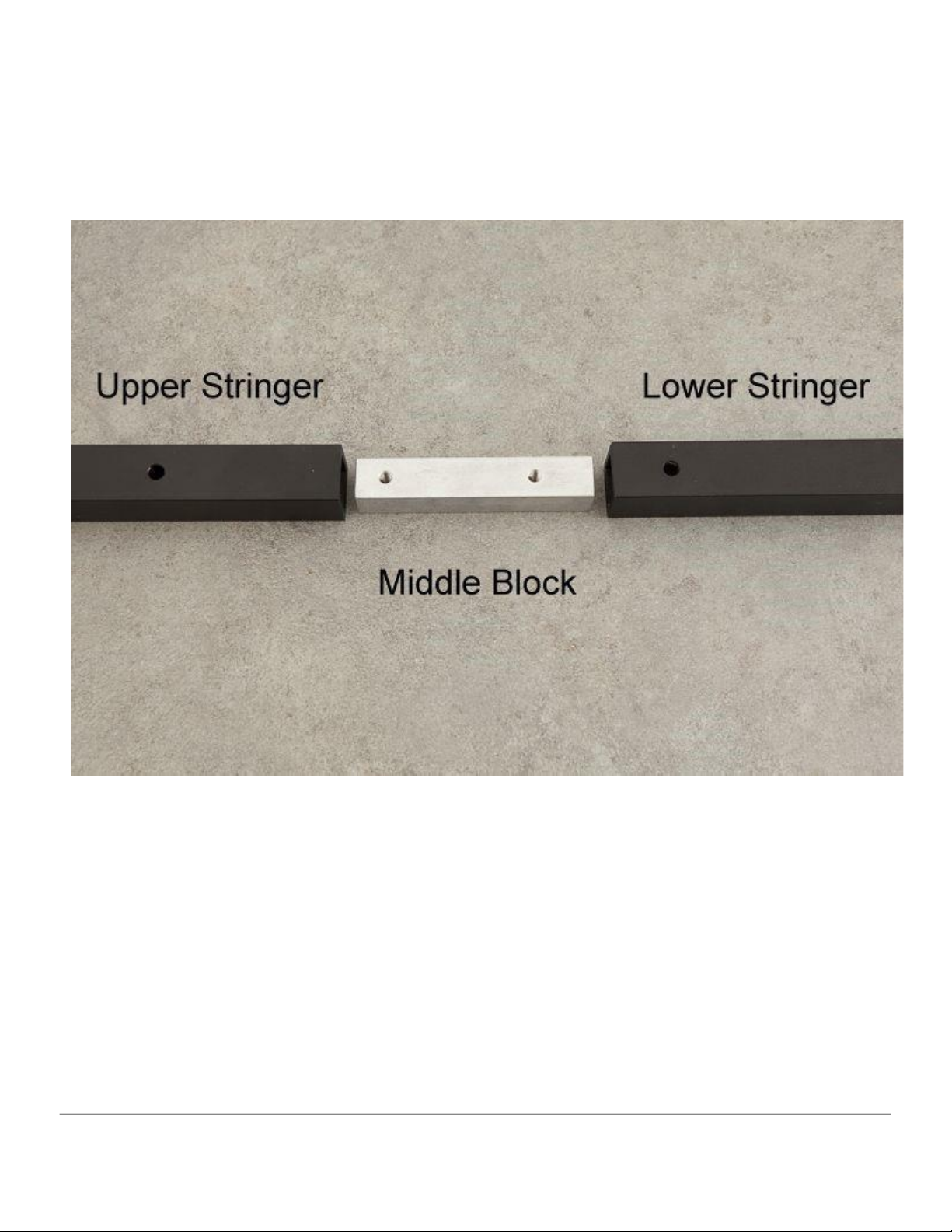
Flip both the Upper Ladder Stringer and the Lower Ladder Stringer over to expose the small hole in the Upper
Ladder Stringer. You can now line up with the threaded hole in the Middle Block.
Slide the Middle Block into the open end of the Upper Ladder Stringer until the threaded hole of the Middle Block
lines up with the small hole in the Upper Ladder Stringer.
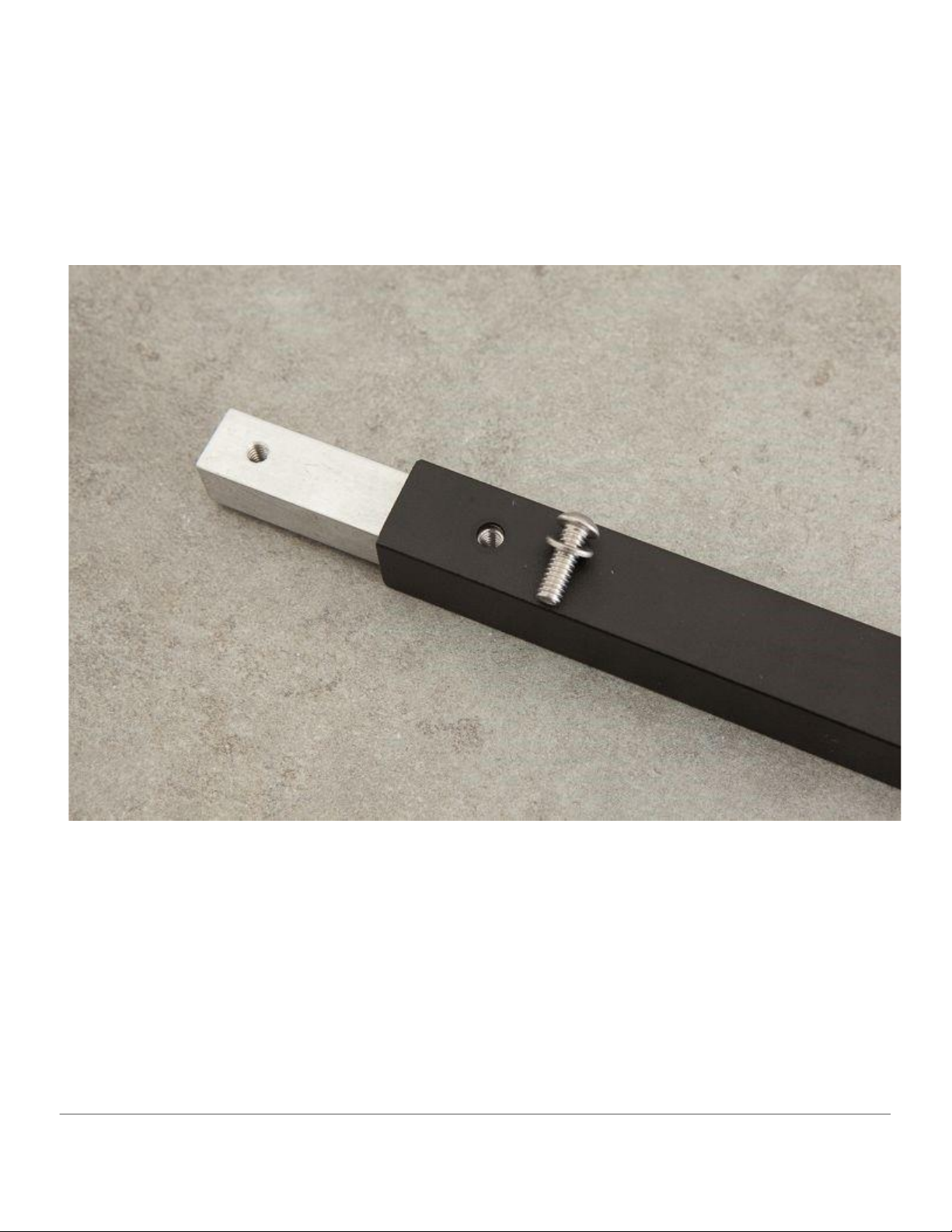
Take a 1/4x20x1 SS Button Head Screw and a 1/4 SS Washer from Hardware Package A and hand thread the screw
into both the Upper Ladder Stringer and the Middle Block. Use a 5/32” Hex Bit Socket and a Ratchet in order to
fully tighten the Button Head Screw. Repeat the process for the other Upper Ladder Stringer as well.