Bedienungsanleitung
Operating Manual
Istruzioni per l’uso
Inhaltsverzeichnis
Table of Contents
Indice
D
I
Bitte bewahren Sie die Verpackung des Modells sorgfältig auf. Beim
Abstellen des Modells bietet sie den besten Schutz. Ein mit beigeleg-
ten Zurüstteilen aufgerüstetes Modell passt nur bedingt wieder in die
Originalverpackung hinein, da diese aus Gründen der Transportsiche-
rung sehr eng sein muss. Es empehlt sich, die Originalverpackung an
gewissen Stellen mit einem scharfen Messer auszuschneiden. Kleinere
Teile des Modells, wie z.B. Puffer, sind wegen Detailtreue als aufge-
rüstete Steckteile ausgeführt und sind daher mit dem Grundkörper
nicht ganz fest verbunden. Beim selbstverschuldeten Verlust möchten
Sie bitte ein solches Teil neu bestellen. ( In diesem Fall können Sie
diese Teile auf dem Ersatzteilweg nachbestellen, eine Reklamation
kann nicht geltend gemacht werden.) • Don‘t throw your box in the
dustbin. If your model is not in use this box will keep it safe. If kits
are mounted on a wagon it will be slightly tight when placing it in
the original box. This guarantees safe transport. It is therefore recom-
manded to cut out certain parts of the original box. To keep the model
like the original, smaller parts (e.g. buffers) had been manufactured
separately from the body and are not tightly xed on it. Therefore they
probably can get lost. In this case you certainly may reorder them but
a complaint would not be acceptable. • Veuillez conserver ce mode
d’emploi ainsi que l’emballage en vue d’un futur emploi. L’emballage
se prête particulièrement bien pour stocker et protêger votre mo-
dèle lorqu’il n’est pas en service. • Un wagon entièrement êquipê
de ses pièces de nition ne rentre plus dans son emballage qu’après
avoir dégagé la place nécessaire à l’aide d’un coûteau n et bien
guisé aux endroits cù sont montés ces piéces. La stabilité et la sécurite
de l’emballage lors du transport du modèle de l’usine à votre detallant
(ou même à vous) impose une réduction au stricte minimum de tou-
te place découpée et non utilisée, raison pour laquelle ces d´coupes
ne peuvent malheureusement pas être aménagées déjà en usine. •
Quelques petites pièces de nition (des tampons p. e.) ne sont pas
moulées d’un seul bloc avec leurs bases, mais séparément rapportées
en vue d’une réalisation plus détaillée. Cela implique le risque de
perte de ces composants. Dans ce cas, vous pouvez commander ces
pièces aux S.A.V. ROCO; nous ne pouvons cependant pas donner suite
à une r´clamation èventuelle à cause de ces pièces perdues. • Heeft
u uw model voorzien van alle insteekdeeltjes, dan past deze niet meer
precies in de doos. Na voorzichtig passen snijdt u met een scherp mes
eerst enige stukjes uit deze doos en u heeft de beste bescherming
voor uw kostbare model bereikt.
Bitte diese Beschreibung zum späteren Gebrauch aufbewahren! •
Please retain these instructions for further reference! • Pière de bien
vouloir con- server ce mode d’emploi en vue d’une future utilisation!
• Conservate queste istruczioni per un futuro utiliozzo! • Deze hand-
leiding altijd bewaren.
Achtung! Bei unsachgemäßem Gebrauch besteht Verletzungs- ge-
fahr durch funktionsbedingte scharfe Kanten und Spitzen • At-
tention! At an incorrect use there exists danger of hurting because
of cutting edgesand tips • Attention! II y a danger de blessure à un
emploi incorrect à cause des aiguilles et arêtes vives! • Voorzichtig! Bij
ondoelmatig gebruik bestaat verwondigsgevaar door scherpe zijkan-
ten en uitsteeksels! • Attenzione! Un inap-propriato uso comporta
pericolo di ferimenti attraverso punte e spignoli taglienti! • Atencion!
Un emploe incorrecto puede causar causar heridas debido a las puntas
y aristas agudas! • Atencao! Por utilizacao incorrecta existe o perigo
de estragos, em virtude de cortes nas abas e nas pontas! • Bemaerk!
Ved ukorrekt brug kan de funktionsbetingede skarpe kanter og spidser
forvolde skade! • Proxoch! Hakatallhlh crhoh egkleiei kin
dunouz mkrot raumatismn, exaipax kopterwn akmwn kai
proexocwqn.
Änderungen von Konstruktion und Ausführung vorbehalten! • We re-
serve the right to change the construction and design! • Nous nous ré-
servons le droit de modier la construction et le dessin! • Ci riserviamo
il diritto di variare la costruzione e il design! • Verandering van model
en constructie voorbehouden.
CZ/SK - Návod na montáž stavebnice: Před stavbou pečlivě prostu-
dujte příložený návod s vyobrazením. Jednotlivé dily odděIte od licích
rámečku a začistěte modelářským nožem nebo pilníkem. Díly roztřídte
dle vyobrazení a postupně slepujte podle pořadi jednotlivých staveb-
nich kroku. K lepení používejte lepidla určená pro plastikové stavebince.
GB
Modelleisenbahn GmbH
A-5101 Bergheim
Plainbachstraße 4
Email: roco@roco.cc
Tel.: 00800 5762 6000
(kostenlos/ free of charge/ gratuit)
International: +43 820 200 668
(kostenpichtig/ chargeable / avec des coûts)
(Zum Ortstarif aus dem Festnetz / local tariff for landline / prix d‘une appel
locale depuis du téléphone xe - Mobilfunk / Mobile max. 0,42€/min.
incl. VAT)
AT|D|CH
16
D
8073974-920 III/21
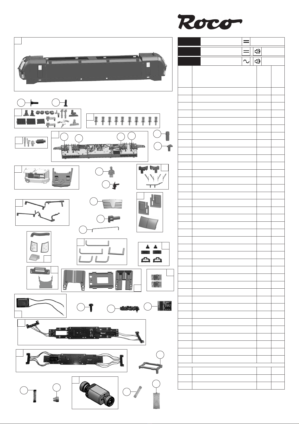
73974
79975
73975
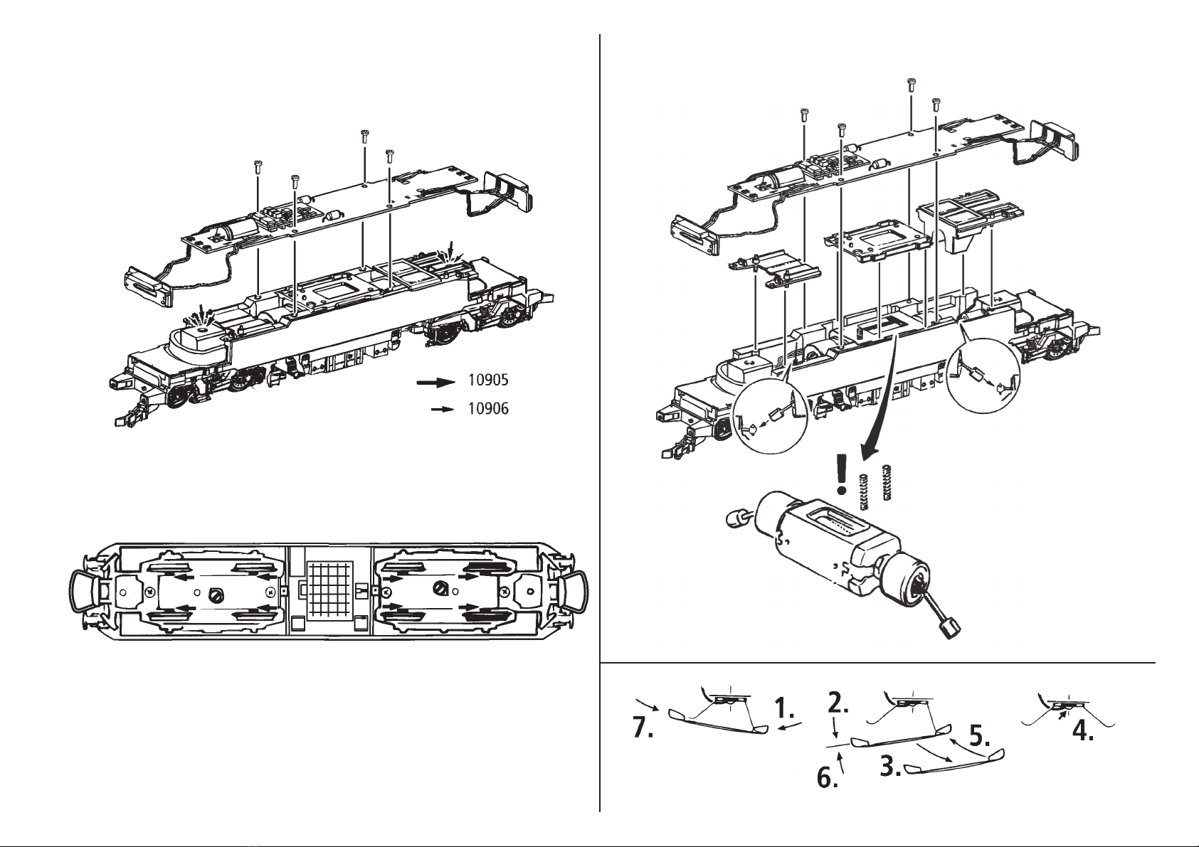
Fig. 1 – 3................................................8 + 9
Fig. 4 – 7..............................................7 + 10
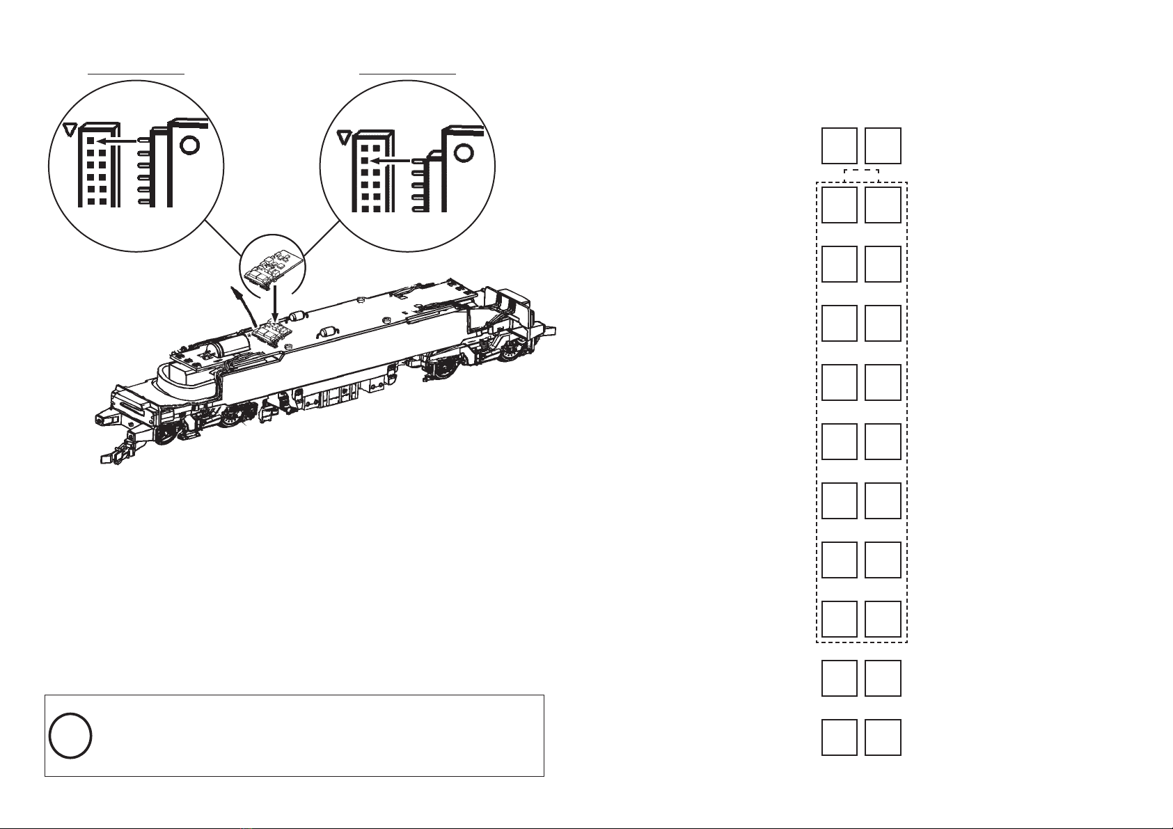
Fig. 8 ...................................................6 + 11
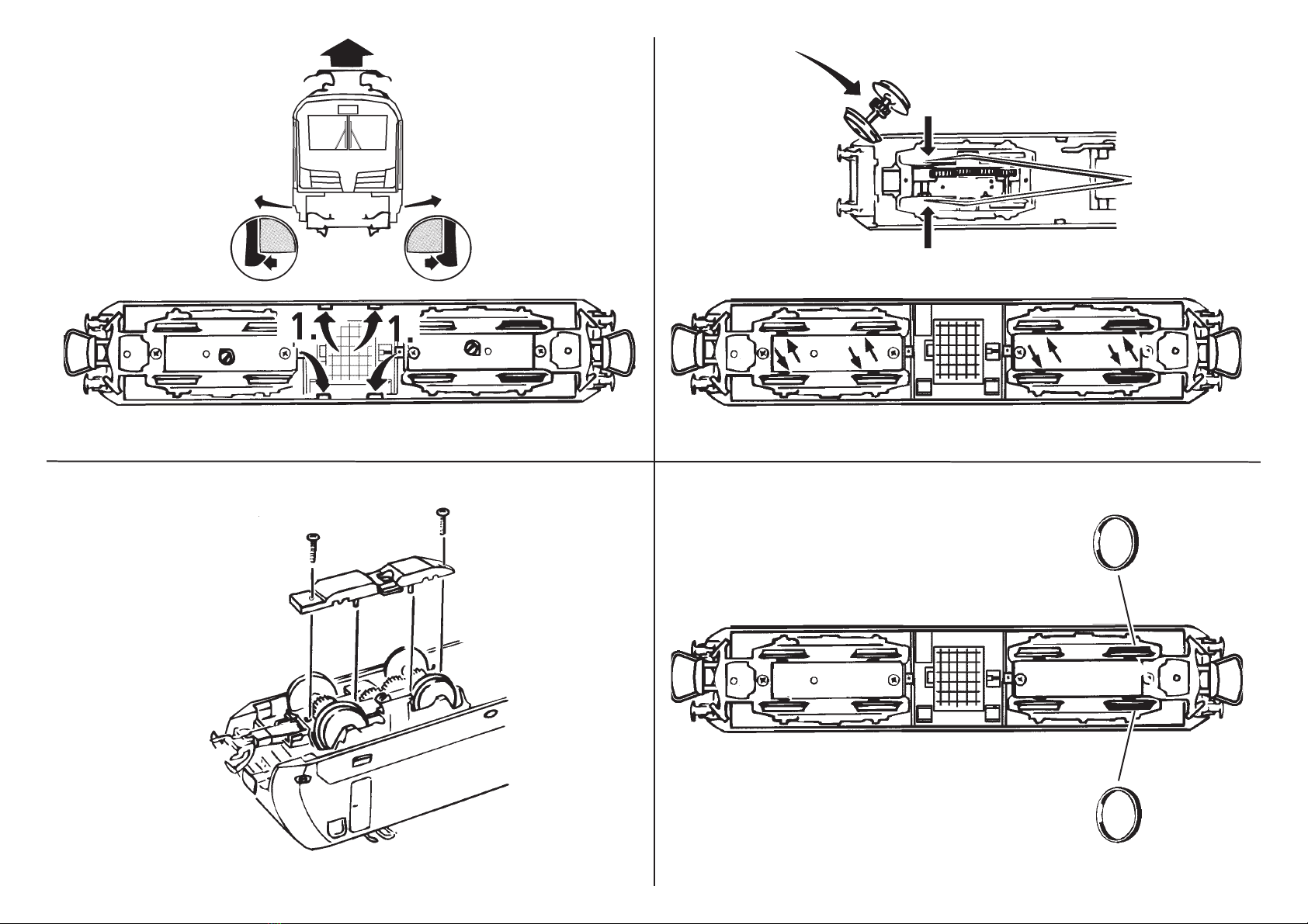
Fig. 9 – 11............................................5 + 12
H0-Modell: Elektrolokomotive
193, MRCE / Mercitalia Rail
H0-model: Electric locomotive
193, MRCE / Mercitalia Rail
Modèle H0: Locomotiva elettrica
193, MRCE / Mercitalia Rail
Inbetriebnahme .............................. 2
artung und ege ..................... 15
Starting locomotive operation ...... 14
Maintenance of the model ............. 3
Messa in funzione della
vostra locomotiva ........................ 14
Manutenzione del vostro modello.. 3