RodinBell D-100 User manual

1
Shenzhen RodinBell Technology Co., Ltd.
D-100 UHF RFID Desktop Reader
User Manual V1.1

2
Catalogue
1. D-10X View ..................................................................................................................................3
1-1: Front View................................................................................................................................3
1-2: Back View.................................................................................................................................3
1-3: Plan View..................................................................................................................................3
2. Reader Configurations ...............................................................................................................4
2.1 Initial Use...................................................................................................................................4
2.1.1 Step 1: Connect The Reader to PC via USB or Serial Port.......................................................4
2.1.2 Step 4: Operating Reader via Demo ........................................................................................5
2.2 Setting RF Parameter ...............................................................................................................6
2.2.1 Setting RF Output Power.........................................................................................................6
2.2.2 Setting RF Spectrum................................................................................................................6
2.3 ISO-18000-6C tag inventory......................................................................................................7
2.3.1 Real Time Mode & Buffer Mode ...............................................................................................7
2.4 Accessing ISO-18000-6C Tag.................................................................................................10
2.4.1 Read tags ..............................................................................................................................10
2.4.2 Write Tags.............................................................................................................................. 11
2.4.3 Lock Tags............................................................................................................................... 11
2.4.4 Kill Tags .................................................................................................................................12
2.4.5 Tag Selection .........................................................................................................................12
2.4.6 Error Display Might Be Returned............................................................................................13
3. Develop your own RFID Application........................................................................................15
4. Installing Driver.........................................................................................................................16

3
1. D-10X View
1-1: Front View
1-2: Back View
1-3: Plan View

4
2. Reader Configurations
2.1 Initial Use
2.1.1 Step 1: Connect The Reader to PC via USB or Serial Port
Method NO.1: You can connect the reader to your PC via USB Cable, as illustrated below:
Next, please switch the DIP to the position as illustrated below:
Method NO.2: You can also connect the reader to PC via RS-232 serial port, as illustrated below:
Next, please switch the DIP to the position as illustrated below:

5
When the indicator light on and sound of a short beep, reader is ready.
Note: Driver will be installed automatically when reader is connected to PC for the first time. But
some computers may fail. In this case, please install driver manually. (please see: Installing
Driver at page 21).
2.1.2 Step 4: Operating Reader via Demo
Put the files that named UHFDemo.exe, reader.dll, customControl.dll into a same folder, and
double-click UHFDemo.exe to run the software.
1. Open the software and it will shows as below:
2. Please select RS232 as Connection if the reader is connected via RS -232 port, or select USB as
Connection if the reader is connected via USB. Choose the corresponding Serial Port and
Baudrate(default baudrate is 115200). As illustrated below:
3. Click Connect , if it succeeds, the Operation History will display as below:

6
4. Text communication with the reader:
Click on Get in Firmware Version or in Reader Identifier, the following screen displays:
Now the reader has been connected to PC successfully.
2.2Setting RF Parameter
After connecting the reader with PC, we need to set some basic RF parameters: RF Output Power & RF
Spectrum. Please select RF Setup as illustrated below:
2.2.1 Setting RF Output Power
RF Output Power is the strength of RF output signal from antenna port whose unit is dBm.
The output power range is 0 - 26dBm. When this setting completes, it will be saved in the reader
automatically even if the power is cut off. The default output power is 26dBm.
2.2.2 Setting RF Spectrum
Set the RF spectrum manually.
Please defer to Frequency parameter tablet in Communication protocol for more information about

7
the carrier frequency.
Frequency range the reader supports: 865MHz-868MHz(ETSI), 902MHz -928MHz(FCC).
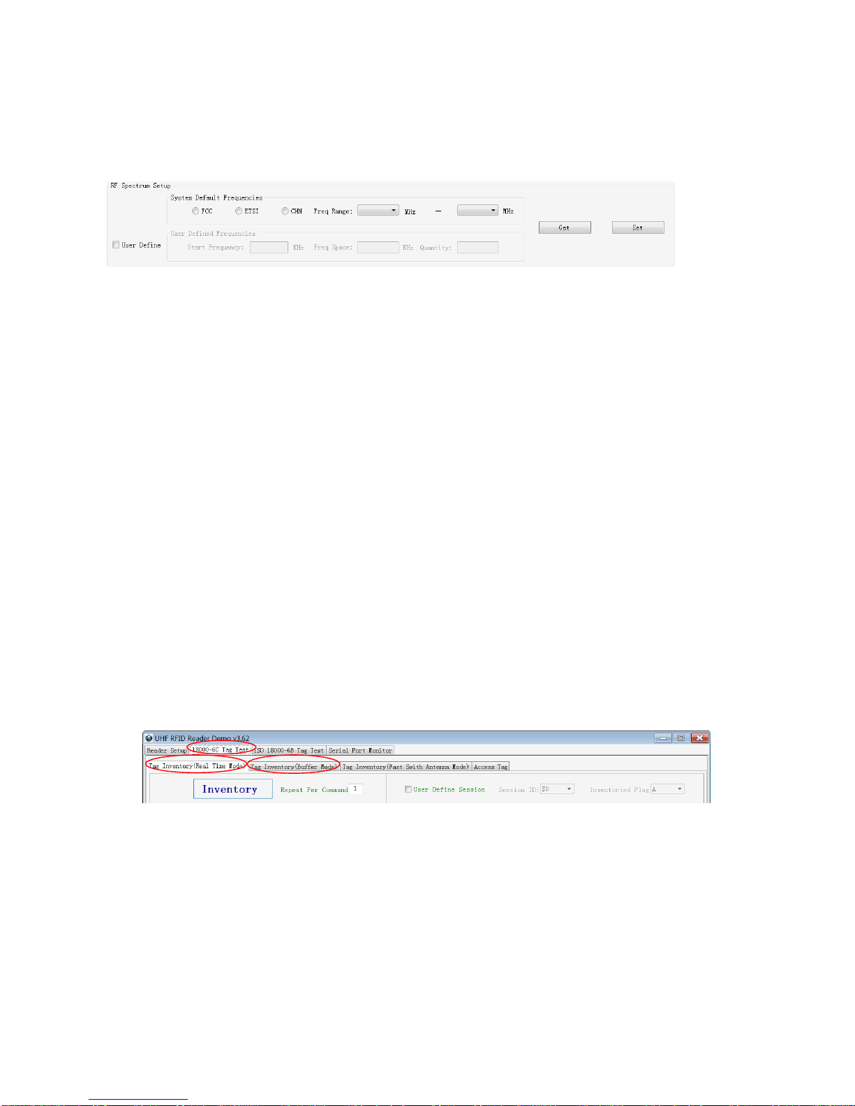
You can set the reader in RF Spectrum Setup->User Define, as illustrate below:
Users can set RF spectrum via these three parameters: Start Frequency, Frequency Interval, The number
of Frequency points.
2.3 ISO-18000-6C tag inventory
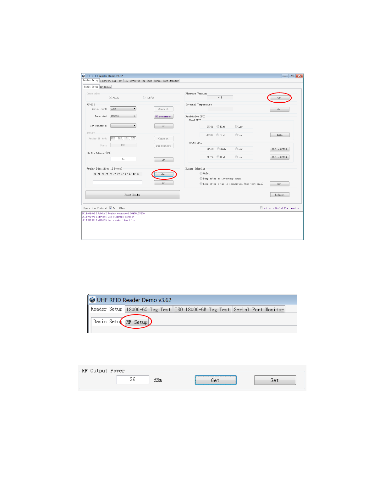
Connect the Reader correctly. Tag operation could be started when RF Setup is completed.
Tag inventory means reader identifying multiple tags’EPC number at the same time. This is the core
function of UHF RFID Reader and one of the standards to judge a reader’s performance.
2.3.1 Real Time Mode & Buffer Mode
The most commonly used mode for tag inventory isReal-time Mode. Data will be uploaded meanwhile
you can get the tags’EPC number instantly. RSSI and Parameter of Frequency are changed and
recorded in real time. Due to its dual CPU architecture, performance of multi-tag identification under
Real-time mode is the best.
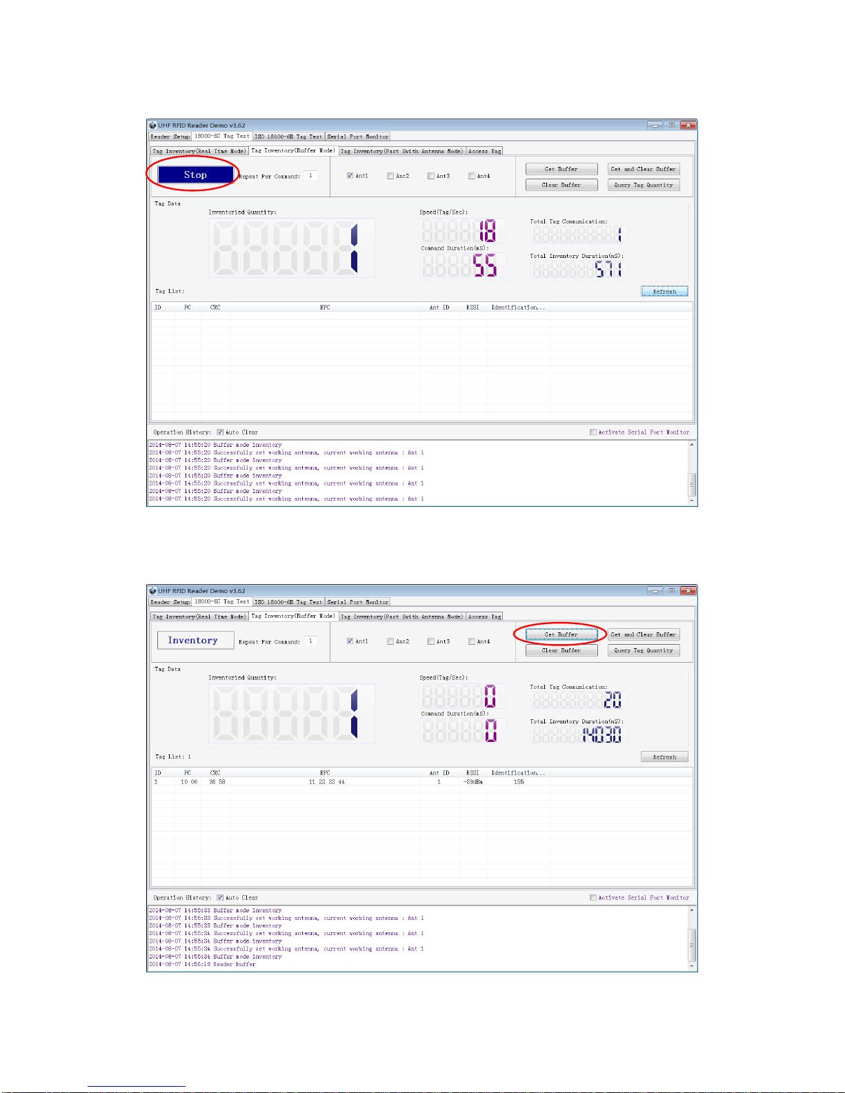
The other is Buffer Mode, the data will be cached and uploaded together when you need them. Under
this mode, the data are without repeat data and can keep in small volume, because the data will be
filtered before being uploaded. But it will take some time to filter duplicate data when reader identifies a
large number of tags. Therefore, its identification efficiency will be slightly lower than real-time mode. Note:
Tags can’t be operated when you extract data in the cache.
Users can choose the appropriate method based on actual situation as illustrated below:
Method NO.1: Real-time Mode
1. Click Tag Inventory (Real Time Mode). Select the connected antenna(s) port. Set the number of
Repeat Per Command, which is the times of repeat inventory command. For example, inventory
command will execute anti-collision algorithm one time when you set the value to 1. It will execute
anti-collision algorithm two times when you set the value to 2...
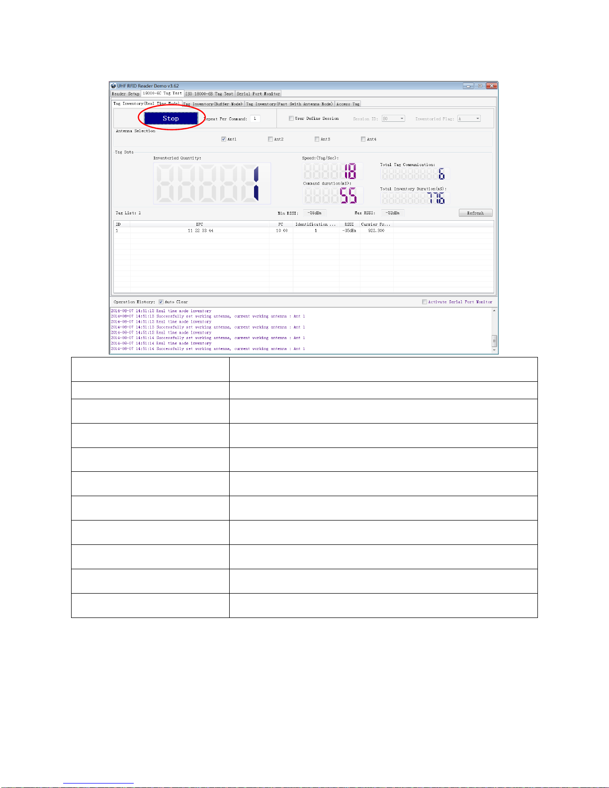
2. Click Inventory, you will find that the EPC number is uploaded immediately and it is real-time updating.
The reader will keep inventory until you click stop as shown below:

8
Inventoried Quantity
Total number of inventory tags since click on Inventory.
Speed
Speed of identification Tag, unit: piece / sec
Total Tag Communication
Total return EPC data of tags (Including repeated data)
Command Duration
Time of each inventory command takes, unit: ms
Total Inventory Duration
Total elapsed time since click on Inventory , unit: ms.
ID
The serial number of data.
EPC
EPC number of tag.
PC
Protocol Control word of tag.
Identification Count
Times of tag identified.
RSSI
The signal strength when tag was identified at the last time.
Carrier Frequency
Carrier frequency of tag which is identified at the last time.
Method NO.2: Buffer Mode
1. Click Inventory, the screen will display as below(single tag & multi-tag inventory):

9
Note: the identified tags won’t be shown in the Tag list.
2. Click Stop first, then click Get Buffer. All the data in cache will be uploaded as illustrated below:

10
Functions description under Buffer Mode:
Get and Clear: Read the data form cache and then clear the cache. It will be empty when you read the
cache again.
Query tag Quantity: If you just want to know how many tags are there in cache without details, click on
this button.
Clear Buffer: Clear the cache and refresh the screen.
2.4 Accessing ISO-18000-6C Tag
Click Access Tag, and the screen will display as following:
2.4.1 Read tags
You can set the parameter(zones to be read, StartAddress and Data Length) as illustrated below:
Note: the unit of Starting Address and Data Length is WORD which is 16 bit double-byte.
Click Read when the parameter setting is completed.
Picture as below shows that one tag has been identified successfully.

11
2.4.2 Write Tags
The area of Write Tag is the same as Read Tag, but you need to provide access password and
information of data to be written.
When the operation done successfully, the screen will display as follows:
Note: The maximum length of one-time write is 32 Word (64 bytes, 512bits).
2.4.3 Lock Tags
A password is necessary to be provided for locking tags. When the operation is completed successfully,
the screen will display as follows:

12
Same as Write Tags, data of identified tags will be displayed in Tag List.
2.4.4 Kill Tags
Password is necessary which can not be 00 00 00 00 before Kill Tags. Therefore, to kill a tag please need
change the content of password via Write Tag Operation first.
When tag is killed successfully, the information will display as follows:
2.4.5 Tag Selection
No matter how many tags in RF region, we just want to access EPC tags which are already identified.
Now, we can use the function of Tag Selection(EPC matching).
1. Tag inventory in Buffer Mode to get all tags’EPC number.
2. Get tags in cache.
3. Access tags and choose the EPC NO. which is needed, as illustrated below:

13
After choosing the tag, please click Select and the screen will display as follows:
We could see that the column on the left for Selected Tag has been selected. Next, all the operations are
based on the tag with this EPC NO.
If you want to cancel the match of EPC, just deselect the column for Selected Tag, as below:
2.4.6 Error Display Might Be Returned
Errors occur if wrong operations done:
◆Inventory success, access failure:
There are two steps to get access to tags: firstly, tag inventory; secondly, access tags. Picture above
shows the inventory is successful, failed to access to tags.
Two reasons why:
1. Parameters incorrect: for example, zones(password/ EPC/ TID/ User) to be read do not exist.
2. Tags beyond the area that the RF could cover: distance of accessing to tags is about 60%-70% of tag
inventory; in this case, please put the tag closer to the antenna.
◆Wrong password:
Reason why: wrong password is set.

14
◆No tags to be operated:
Reason why: Tags beyond the area that the RF could cover.
For more information about the operation history returned, please defer to the document: UHF RFID
Reader Serial Interface Protocol V3.1.

15
3. Develop your own RFID Application
Most functions of the reader can be operated through the demo. But in practical applications, user might
need to develop their own applications. Please defer to the document: UHF RFID Reader Serial
Interface Protocol V3.1.The reader follows the definition both of the RS - 232 and TCP / IP interface.
Demo provides an important function of recording serial transmission, so that users can quickly grasp the
content of communication protocol in practice. Please defer to the screenshot below and select Activate
Serial Port Monitor, all uplink and downlink serial data will be recorded, as illustrated below:
Notes:
1. Response speed of Demo will slow down after opening the Activate Serial Port Monitor. Please turn
off this function when it is not needed.
2. Data in violet blue color is sent to the reader by PC, and data in red color is the returned information
from reader to PC.
3.Manual Input Command is used to debug serial command, which could calculate the checksum
automatically.
4. UHF RFID Reader Serial Interface Protocol V3.1, this document includes the integral source codes of
the demo (Based on C # of .Net platform) to help users develop applications on the reader. Thank you!

16
4. Installing Driver
1. Open the D-100 Driver folder.
2. Double click on CDM20828_Setup.exe, the following screen displays:
3. Click on Extract:
After installation is complete, we could connect reader to PC successfully.

17
FCC Statement
This device complies with part 15 of the FCC Rules. Operation is subject to the following two conditions:
(1) This device may not cause harmful interference, and (2) this device must accept any interference
received, including interference that may cause undesired operation.
Changes or modifications not expressly approved by the party responsible for compliance could void the
user's authority to operate the equipment.
NOTE: This equipment has been tested and found to comply with the limits for a Class B digital device,
pursuant to Part 15 of the FCC Rules. These limits are designed to provide reasonable protection against
harmful interference in a residential installation. This equipment generates, uses and can radiate radio
frequency energy and, if not installed and used in accordance with the instructions, may cause harmful
interference to radio communications. However, there is no guarantee that interference will not occur in a
particular installation. If this equipment does cause harmful interference to radio or television reception,
which can be determined by turning the equipment off and on, the user is encouraged to try to correct the
interference by one or more of the following
Measures:
-- Reorient or relocate the receiving antenna.
-- Increase the separation between the equipment and receiver.
-- Connect the equipment into an outlet on a circuit different from that to which the receiver is connected.
-- Consult the dealer or an experienced radio/TV technician for help.
This equipment complies with FCC radiation exposure limits set forth for an uncontrolled environment.
This equipment should be installed and operated with a minimum distance of 20 cm between the radiator
and your body.
Table of contents
Other RodinBell Card Reader manuals