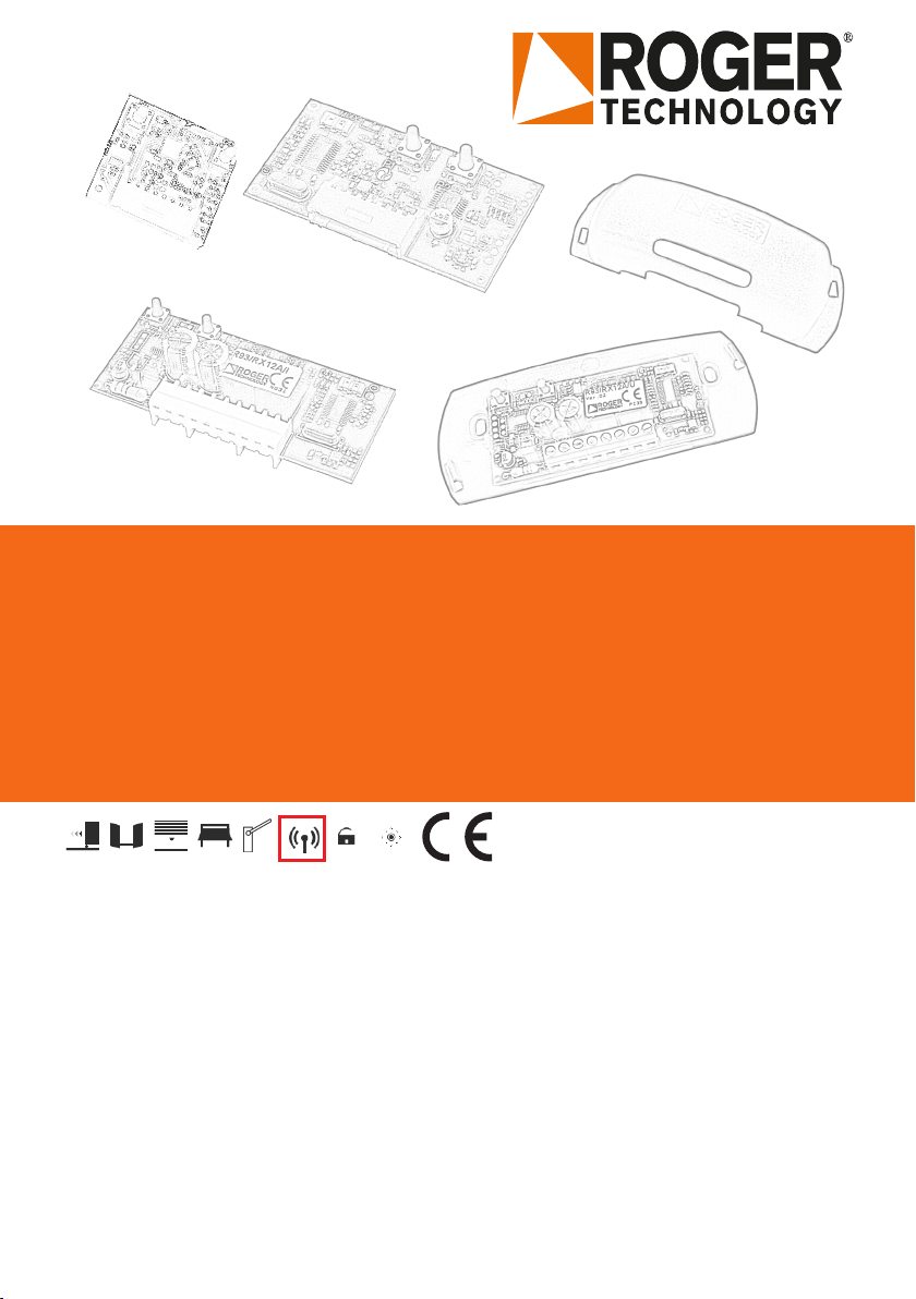
Roger Technology H93/RX22A/I Product manual
IS50 Rev06 18/11/2019
H93/RX22A/I - H93/RX20/I
R93/RX12A/I - R93/RX12A/U
Ricevitori Radio
Radio Receiver
Istruzioni originali
IT - Istruzioni ed avvertenze per l'installatore
EN - Instruction and warnings for the installer
DE - Anleitungen und Hinweise für den Installateur
FR - Instructions et avertissements pour l'installateur
ES - Instrucciones y advertencias para el instalador
PT - Instruções e avisos para o instalador

2
LED LED ON
1 click
LED
OFF
P1 P2
L1
L1
L1
L2
L2
LED x4
L1
L1
L2
L2
L1
L1
L2
L2
L1
L1
L2
L2
L2
A
A
B
B
Fig. 6
Fig. 5
Fig. 3
Fig. 2Fig. 1
Fig. 4
32
60
12
P1
L1 L2
P2
31
34
P1
L1 L2
P2
12
H93/RX20/I H93/RX22A/I
R93/RX12A/U
R93/RX12A/U
ESEMPIO - EXAMPLE
R93/RX12A/I
51,6
126 24,5
SELEZIONE TENSIONE
VOLTAGE SELECTION
12V
24V
83
P1
L1 L2
P2
+12/24V
-12/24V
CH1
CH1
CH2
CH2
1839
83
P1
L1 L2
P2
SELEZIONE TENSIONE
VOLTAGE SELECTION
12V
24V
+12/24V
-12/24V
CH1
CH1
CH2
CH2
4
1 WARNINGS!
This installation manual is intended for qualied personnel only.
ROGER TECHNOLOGY cannot be held responsible for any damage
or injury due to improper use or any use other the intended usage
indicated in this manual.
Before installing the product, make sure it is in perfect condition:
In case of doubts, do not use the product and refer exclusively to
professionally qualied personnel.
The R93/RX12A/U radio receiver must be powered by a class 1
source (ES1 - safety extra-low voltage SELV). The source must be
of limited power with adequate protection against overcurrents and
short circuit (PS1). Use a 50mA delayed acting fuse to protect the
device (T50mA).
2 Technical specications
H93/RX20/I H93/RX22A/I R93/RX12A/I
R93/RX12/U
POWER SUPPLY 5V 5V 12/24
CONSUMPTION 15 mA 15 mA 30 mA
NUMBER OF OUTPUTS 2
TYPE OF OUTPUTS OPEN COLLECTOR RELAY
TYPE OF DECODING FIXED CODE
NUMBER OF
COMBINATION CODES 65.536
RELAY MAXIMUM
CURRENT AND VOLTAGE /0,5A
24V
NUMBER OF CODES THAT
CAN BE STORED 50 500
RECEPTION FREQUENCY 433.92 MHz
MODULATION AM/ASK
SENSITIVITY -107dBm
INPUT IMPEDANCE 50Ω
ANTENNA CONNECTION RG58 Cable (max length 10m)
Avoid cables with joints
OPERATING
TEMPERATURE -10°C +55°C
DIMENSIONS (mm)
34x31x12 61x32x12
R93/RX12A/I
83x39x18
R93/RX12A/U
126x52x25
3 Description of Series H93 radio receiver
Series H93 receivers (g. 1-2) must be inserted in the plug-in connector arranged
on the ROGER central units.
The Series H93 receivers have two channels (P1 / P2) with open collector output.
Setting the function of the channel/channels of parameters 76 and 77 of the
ROGER control central units.
IMPORTANT: When the Series H93 receiver is installed on the control units for
garage doors H70/10CC and H70/14CC, only channel 2 (P2) is enabled with the
step by step function.
4 Description of the Series R93 radio receiver
The Series R93 receivers (g. 3-4-5) are equipped with two channels (P1 / P2)
with normally open relay output.
IMPORTANT: When receiver R93/RX12/I is installed on the ROGER control
units, channel 1 (P1) is enabled for the step-by-step function.
Channel 2 (P2) can be connected and congured at will (clamps CH2).
5 Storing a remote control key in the receiver
(Fig.6)
1. Insert/connect the receiver to the control unit
2. Switch the controller unit on.
3. Press P1 or P2 once (depending on the function to be enabled) on the
receiver.
4. When LED L1 or LED L2 on the receiver ashes slowly, press the key on the
transmitter where the function is to be stored.
5. When LED L1 or L2 remains on for 1 second, the transmitter has been stored.
6. LED L1 or L2 ashes slowly again and other transmitters can be stored
during this time.
7. Quitting the procedure is done automatically if no further transmitters are
stored.
NOTE:
• During the storing stage, should LED L1 or L2 fail to switch on or should
some fast ashing occur, it means that the transmitter was already saved
on the other channel.
• It is impossible to store the same key of the transmitter on both channels
of the receiver.
• During the storing stage, should LED L1 and L2 ash rapidly for 4 s, it means
that the memory is full.
6 Receiving a code
When the receiver radio receives a stored code, LED L1 or L2 switches on and the
congured output gets activated.
Should the code not have been stored, LED L1 and L2 switch on briey.
7 Cancellation of a code
1. Press for 4 seconds button P1 or P2 on the receiver relative to the channel on
which the code of the transmitter is to be cancelled. LED L1 or L2 switches
on permanently to then ash rapidly.
2. Release button P1 or P2. LED L1 or L2 ashes rapidly for 4 s.
3. Press the button of the transmitter to be cancelled.
4. The LED L1 or L2 lights for 1 s.
5. The code was cancelled.
6. To cancel another code, repeat the procedure.
NOTE:
• If the code was not stored, LED L1 or L2 ashes rapidly.
8 Complete memory erasure
1. Press simultaneously buttons P1 and P2 for 4 seconds on the receiver.
2. LED L1 and L2 ash simultaneously (5 ashes).
3. The memory is erased
NOTE. It is suggested that a total erasure of the memory gets carried out at
rst switch-on.
9 Anomalies alert
• If LED L1 or L2 ashes rapidly and continuously, it means that the memory is
damaged. The receiver cannot operate.
10 Disposal
This product may only be uninstalled by qualied technical
personnel, following suitable procedures for removing the product
correctly and safely.
This product consists of numerous different materials.
Some of these materials may be recycled, while others must
be disposed of correctly at the specic recycling or waste
management facilities indicated by local legislation applicable for
this category of product.
Do not dispose of this product as domestic refuse.
Observe local legislation for differentiated refuse collection, or hand the product
over to the vendor when purchasing an equivalent new product.
Local legislation may envisage severe nes for the incorrect disposal of this
product. Warning! some parts of this product may contain substances that are
harmful to the environment or dangerous and which may cause damage to the
environment or health risks if disposed of incorrectly.
11 Declaration of Conformity
The undersigned, representing the following manufacturer
Roger Technology - Via Botticelli 8, 31021 Mogliano V.to (TV)
hereby DECLARE that the appliance described hereafter:
Description: Radio Receiver
Model: Serie H93 / R93
Is in conformity with the legislative provisions that transpose the following di-
rectives:
– 2014/53/EU RED Directive;
– 2011/65/EU RoHS Directive;
– 2015/863/UE - Direttiva RoHS 3;
and that all the standards and/or technical requirements indicated as follows
have been applied:
EN 300 220-1 V3.1.1;
EN 300 220-2 V3.2.1;
EN 301 489-1 V2.2.1;
EN 301 489-3 V2.1.1;
EN 62368-1:2014+A11:2017+AC:2017
Place: Mogliano V.to
Date: 25/02/2019 Signature
EN
This manual suits for next models
3
Other Roger Technology Receiver manuals


Popular Receiver manuals by other brands


Ramsey Electronics
Ramsey Electronics FR-10 Assembly and instruction manual

Topfield
Topfield SRP-2110 user guide

SatLab
SatLab SLC user manual

Harman Kardon
Harman Kardon AVR 525 reference guide

BWI Eagle
BWI Eagle AIR-EAGLE SR 38HC-2000 Product information bulletin

Yamaha
Yamaha CinemaStation DVR-S150 owner's manual