Roger H85/TTD Series Product manual

|
ROGER ACCESSORI
IS112 Rev.01
10/05/2015
ROGER TECHNOLOGY
Via S. Botticelli 8 • 31021 Bonisiolo di Mogliano Veneto (TV) • ITALIA
P.IVA 01612340263 • Tel. +39 041.5937023 • Fax. +39 041.5937024
info@rogertechnology.com • www.rogertechnology.com
automazioni evolute

2
IT
alle corren e tensioni richieste, rispeare le caraerische
tecniche del prodoo.
Tasera a soramento a codice numerico che può essere
ulizzata in due modi dieren:
• collegata all’interfaccia di controllo
tramite un cavo a due conduori da 0.5mm2; dopo
aver digitato uno dei codici utente memorizza nella
memoria dell’interfaccia, è possibile avare uno fra
quaro relays a bordo dell’interfaccia.
• alimentandola direamente a 12-24Vdc, può essere
collegata ad un sistema di controllo accessi scegliendone
la modalità di funzionamento mediante il dip-switch
a 3 vie (Wiegand 26 bit, 37 bit, 50 bit oppure ISO2).
La descrizione di queste funzionalità è riportata nel
.
La tasera dispone di retroilluminazione a 6 LED bianchi:
normalmente aenuata in stand-by, aumenta di intensità
sorando i tas.
Nel caso di ulizzo abbinato con , il numero
massimo di tasere collegabili ad una singola interfaccia di
controllo è 4, permeendo così avazioni da più postazioni
remote.
La sicurezza è garanta da un protocollo di comunicazione
proprietario sviluppato da Roger Technology che si avvale
della criptatura dinamica dei da, rendendo impossibile la
decodica della comunicazione; l’interfaccia dispone di un
relay ausiliario di allarme, che si ava quando rileva un
tentavo di manomissione del sistema.
E’ possibile memorizzare un massimo di 500 codici utente,
ciascuno dei quali può avere un massimo di 6 cifre.
La memorizzazione dei codici ed ogni altra operazione viene
eseguita agendo sulla tasera (senza necessità di accedere
all’interfaccia) previa conoscenza della password di sicurezza.
Tale password deve essere personalizzata durante
l’installazione, perché di fabbrica tue le interfacce hanno
la stessa password ().
Si consiglia di ulizzare codici utente no a 5 cifre per avere
un’oma sicurezza del sistema e contemporaneamente
la massima facilità d’uso; per gli uten più esigen
che desiderano la massima sicurezza è disponibile una
modalità speciale, descria nel paragrafo 6 FUNZIONI
AVANZATE: MASCHERAMENTO DEL CODICE.
E’ possibile collegare all’interfaccia anche tasere della
serie , purché il numero complessivo di tasere
sia al massimo 4.
La tasera a codice numerico esiste in tre versioni:
: versione per ssaggio a parete.
: versione per ssaggio su colonnina
: versione ad incasso.
Interfaccia per decodica delle tasere:
: versione con contenitore da esterno IP54
Codici per par di ricambio:
: ricambio tasera, comprende tu i
componen mostra .
: ricambio interfaccia, scheda eleronica
(, deaglio F).
Leggere aentamente le istruzioni prima
di eseguire l’installazione.
L’installazione deve essere eeuata solo
da personale tecnico qualicato in base
alle normave vigen.
Auare i collegamen con cavi adegua

3
TENSIONE DI ALIMENTAZIONE INTERFACCIA 24 Vac-dc; 12 Vdc
ASSORBIMENTO DI CORRENTE 1 tasera 25mA
1 tasera + interfaccia in stand-by 50mA
1 tasera + interfaccia con relay avo 60mA
NUMERO MASSIMO DI TASTIERE COLLEGABILI 4
NUMERO DI USCITE DISPONIBILI 4 di comando; 1 di allarme
TIPO DI ATTIVAZIONE USCITE: impulsiva (durata avazione: 350ms)
TIPO DI USCITA relay, contao puro
MASSIMA POTENZA COMMUTABILE (ESCLUSE LAMPADINE) carico in ac-dc: 60VA/24W corrente massima: 1A
RITARDO ALL’ATTIVAZIONE RELAY 100ms
NUMERO DI CODICI UTENTE MEMORIZZABILI NELL’INTERFACCIA 500
MASSIMO NUMERO DI CIFRE PER CODICE UTENTE 6
MINIMO NUMERO DI CIFRE PER CODICE UTENTE 3
LUNGHEZZA MASSIMA CAVO DA INTERFACCIA A TASTIERA 100m (cavo a due conduori di sezione 0.5mm2)
RETROILLUMINAZIONE TASTIERA 6 LED bianchi, due livelli di intensità
TEMPERATURA DI FUNZIONAMENTO -10°C ... +55°C
GRADO DI PROTEZIONE IP54
DIMENSIONI PRODOTTO
dimensioni in mm. 75x77x60 Peso: 104g
dimensioni in mm. 75x77x41 Peso: 100g
dimensioni in mm. 75x98x58 Peso: 240g
dimensioni in mm. 158x119x76 Peso: 279g
TENSIONE DI ALIMENTAZIONE TASTIERA 12 Vdc; 24 Vdc
PROTOCOLLI DI COMUNICAZIONE Wiegand 26 bit / 37bit / 50bit
ISO2 (“magnec stripe”)
TIPO DI USCITA digitale
LIVELLI DI TENSIONE IN USCITA 5Vdc a riposo (passivi, tramite resistenza di pull-up interna 2k7)
0Vdc (avi, forza da transistor)
NUMERO MASSIMO DI TASTIERE COLLEGABILI 5 (con idenca modalità di funzionamento)
I tas da a assieme ai tas asterisco * e cancelleo #
permeono di avare le sequenze di cambio password,
memorizzazione/cancellazione codice, cancellazione
completa dei codici e altro ancora. Quaro tas hanno una
doppia funzione essendo anche ulizzabili per avare una
delle uscite A, B, C, D dell’interfaccia:
• Tasto / A: avazione uscita
• Tasto / : avazione uscita
• Tasto / C: avazione uscita
• Tasto * / : avazione uscita
La tasera dispone di un LED verde ed uno rosso (vedere
, deaglio A: rispevamente LV e LR), e di un
buzzer: ques vengono usa per dare le segnalazioni
durante la digitazione e nelle varie fasi di funzionamento.
La tasera è dotata di una retroilluminazione a 6 LED
bianchi, che si intensica quando si preme uno dei tas
(tasera ava) e torna a livello basso quando è in stand-by.
Descrizione dei morse ():
SYNC, posivo dell’alimentazione con segnale di
sincronismo
negavo dell’alimentazione e del sincronismo
SYNC
Non disponibili
Non ulizza con interfaccia
ATTENZIONE! Per ulizzare la tasera a soramento con
l’interfaccia , impostare sul dip-switch (
) la seguente combinazione: ===ON.
L’interfaccia ( ) dispone di due LED di
segnalazione per il normale funzionamento (, verde
e , rosso) e di 4 LED per dare segnalazioni in fasi di
funzionamento parcolare (avazione dell’uscita a relay;
assegnazione delle tasere in fase di programmazione).
Sono disponibili 4 uscite di comando , ,
e associate ai corrisponden tas 1/A,
4/, 7/C, */, ed un’uscita di allarme (, contao
normalmente chiuso; si apre se viene rilevata un’anomalia
di funzionamento). L’uscita di allarme è abilitabile agendo

4
sul jumper (, deaglio A).
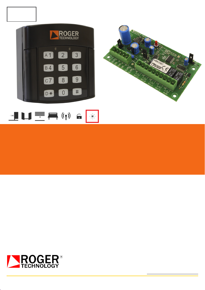
Descrizione dei morse:
alimentazione 24Vac-dc oppure 12Vdc (vedere
, deaglio C)
, ingresso di abilitazione delle uscite di
comando (contao N.A.): chiudendo il contao
verso il morseo le uscite sono abilitate.
, posivo dell’alimentazione con segnale di
sincronismo per le tasere.
, negavo dell’alimentazione delle tasere;
comune per ingresso ENA.
non disponibili.
, uscita di comando A (contao N.A.).
, uscita di comando (contao N.A.).
, uscita di comando C (contao N.A.).
, uscita di comando (contao N.A.).
, uscita di ALLARME (contao N.C.); il contao
si apre quando si rileva una condizione di allarme.
Per escludere questa funzione, vedere ,
deaglio E.
Dopo aver stabilito il punto di installazione, in relazione
alla versione di prodoo a disposizione, il ssaggio si
esegue nello stesso modo (vedere ).
• Togliere le mostrine a copertura delle sedi per le vi di
ssaggio (, deaglio ).
• Con le due vi in dotazione procedere al ssaggio della
tasera al supporto previsto.
• Rimeere in posizione le mostrine, facendo aenzione
al correo incastro.
Fissare l’interfaccia ulizzando le vi in dotazione (vedere
).
Portare l’alimentazione all’interfaccia e collegare le tasere
mediante cavo di sezione 0.5mm2; curare che la massima
lunghezza di cavo tra interfaccia e tasera non superi i 100m.
Impostare il jumper sull’interfaccia in relazione alla
tensione di alimentazione (vedere , deaglio C).
ATTENZIONE! Se l’alimentazione dell’interfaccia non viene
fornita da una centrale ROGER, alimentare l’interfaccia
esclusivamente con un alimentatore di sicurezza: l’ulizzo
di alimentatori non di sicurezza può provocare pericolo.
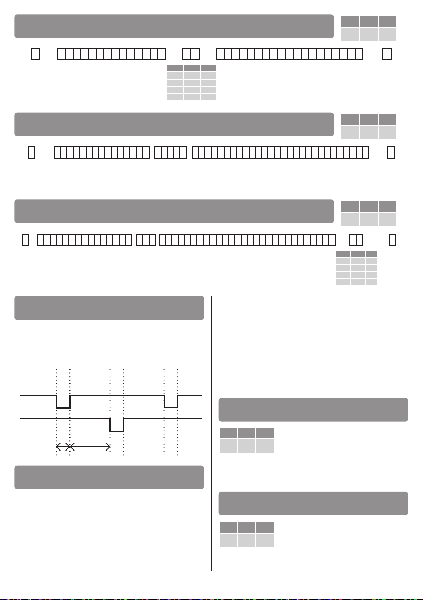
Impostare il dip-switch della tasera nel modo seguente:
===ON (vedere ).
• Dare alimentazione all’interfaccia, alimentando così
anche le tasere ad essa collegate: i 6 LED sulla scheda
di interfaccia si accenderanno in sequenza, come
diagnosca di funzionamento.
• L’interfaccia dispone di un ingresso di abilitazione (ENA,
morseo ) che, se chiuso da un contao esterno (orologio)
verso il morseo fornisce il consenso alla chiusura del
contao di uscita , , , ; questo
signica che se anche su una tasera si digita un codice
utente e si richiede l’avazione di un relay, questo sarà
avato solo se l’ingresso ENA risulterà abilitato. Nel caso
non sia previsto un contao orologio, posizionare il jumper
in posizione “” (vedere , deaglio ).
• Si deve procedere ora all’apprendimento delle
tasere collegate, operazione che viene eseguita
dall’interfaccia la quale assegna ad ognuna di esse un
numero idencavo. Questo permeerà nel normale
funzionamento di riconoscere tentavi di forzare la
sicurezza del sistema (esempio: si cerca di conneerei
una tasera che non è abilitata).
Premere e tenere premuto per almeno 10 secondi il tasto
PROG:
• dopo i primi 4 secondi si ha l’accensione in sequenza dei
LED A> > C>
• dopo altri 4 secondi i LED A,,C, si spengono;
connuare a tenere premuto il tasto PROG
• raggiunto il tempo massimo (10 secondi) i LED A,,C,
iniziano a lampeggiare tu insieme, mentre il LED
verde e rosso sono spen, segnalando l’ingresso in
modalità di apprendimento; a questo punto le tasere
collegate segnalano a loro volta di essere pronte, mediante
l’accensione alternata dei LED verde e rosso (LV e LR)
NOTA: se per un’errata manovra non si arriva a questa
situazione e si accende il LED verde , togliere e
dare nuovamente alimentazione all’interfaccia, e
ricominciare daccapo. In alternava, aspeare 20
secondi per il reset della modalità (i LED A,,C, si
spengono), e ricominciare daccapo.
• seguendo un numero d’ordine progressivo (1, 2, 3, 4),
portarsi alla tasera 1 e premere tre volte il tasto cancelleo
#; se l’assegnazione del codice da parte dell’interfaccia
è andata a buon ne, il buzzer della tasera dà una
segnalazione prolungata e rimane acceso il LED verde
LV. Sull’interfaccia il primo dei LED A,,C, lampeggian
rimane acceso sso, e gli altri connuano a lampeggiare. I
LED , Ce danno lo stato di assegnazione delle tasere 2,
3 e 4; procedere come descrio per la tasera 1
• eseguita l’assegnazione dell’ulma tasera (se sono
installate due tasere, sull’interfaccia avremo i LED Ae
accesi ssi, Ce ancora lampeggian), premere il tasto
PROG per 2”: si esce dalla modalità di apprendimento
e il LED verde inizia a lampeggiare, segnalando la
comunicazione con le tasere
• modicare la password di sicurezza (si veda paragrafo 5.2);
annotare in modo adeguato e sicuro la nuova password.
ATTENZIONE! Questa operazione è obbligatoria per
mantenere il livello di sicurezza dell’installazione,
in caso contrario esiste la possibilità che venga
memorizzato un codice in maniera fraudolenta e di
conseguenza un malintenzionato potrebbe avare i
relays dell’interfaccia ulizzando tale codice.
• Cancellare completamente la memoria dell’interfaccia
(si veda il paragrafo 5.3 CANCELLAZIONE COMPLETA
DELLA MEMORIA)
• Memorizzare almeno un codice utente nella memoria
della tasera (si veda paragrafo 5.4 MEMORIZZAZIONE
DI UN CODICE UTENTE)
ATTENZIONE! La password assegnata di fabbrica è .
E’ obbligatorio modicare la password per garanre la
sicurezza dell’installazione.
Indichiamo con <vecchia password> la sequenza di numeri
che la compongono, e con <nuova password> la password che
si desidera impostare; digitare dunque la seguente sequenza:

5
* * <vecchia password> #
il led rosso si accende sso. Poi digitare:
<nuova password> # <nuova password> #
Procedura andata a buon ne: si accende il LED verde e si
ava il buzzer per 2”. In caso contrario si ha la segnalazione
di errore (5 lampeggi veloci del LED rosso LR, accompagnato
dall’avazione intermiente del buzzer; vedere paragrafo 7).
ESEMPIO
Per cambiare la password con digitare la
sequenza:
Se si smarrisce la password è possibile sbloccare
l’interfaccia contaando l’assistenza.
Indichiamo con <password> la sequenza di numeri che
compongono la password; per eliminare tu i codici
utente dalla memoria, digitare la seguente sequenza:
# # * <password> # # *
Se la password inserita è correa il LED verde e rosso
(LV e LR) lampeggiano lentamente per 2”, coadiuva
dall’avazione contemporanea del buzzer.
In alternava è possibile cancellare i codici utente
agendo sull’interfaccia; togliere alimentazione, tenere
premuto il tasto PROG dell’interfaccia e dare nuovamente
alimentazione senza rilasciare il tasto.
• Nei primi 4 secondi si accendono i 4 LED di funzione
A,,C, e si spengono i LED e .
• Successivamente si spengono i 4 LED A,,C, e si
accendono i LED e : rilasciare il tasto PROG in
questo momento.
Si entra in modalità di cancellazione, evidenziata dal
lampeggio di e per 4 secondi.
ATTENZIONE!
Vengono cancella tu i codici utente ma non i numeri
idencavi delle tasere e nemmeno la password di
sicurezza.
Indichiamo con <password> la sequenza di numeri che
compongono la password, con <nuovo codice> il codice
utente che si desidera memorizzare e con <A/B/C/D> una
qualunque sequenza di tas di funzione che si desidera
abilitare per l’utente che ulizzerà questo codice, in
modo che possa avare il numero desiderato di uscite
sull’interfaccia; digitare la seguente sequenza:
* <password> *
Se la password è correa, si accende il LED rosso LR. Poi
digitare:
<nuovo codice> # <A/B/C/D> #
si spegne il LED rosso LR e si accende quello verde LV per
2”, ed il buzzer rimane avo nché si spegne il LED.
NOTA: se si vuole abilitare tu i quaro tas di canale,
è possibile evitare di premere in sequenza i tas A,,C,
passando direamente alla digitazione di #.
ESEMPI
Con password , si vuole memorizzare il codice utente
abilitando tu i tas di comando, digitare la sequenza:
Con password , si vuole memorizzare il codice
abilitando solo il tasto :
Per avare uno dei relays di uscita dell’interfaccia
digitare il codice utente seguito da tasto asterisco *. Se
il codice digitato è presente in memoria si accende il LED
verde LV, a questo punto premendo un tasto di funzione
(purché sia stato abbinato a quel codice utente, in fase di
memorizzazione, e il contao ENA sia abilitato) si ava
il relay dell’interfaccia associato al tasto premuto: il LED
verde LV rimane acceso. Sull’interfaccia si accende il LED
A,,C, in corrispondenza del relay avo.
L’avazione del contao è sempre di po impulsivo, di
durata 350ms: mantenere il dito sul tasto non permeerà
di prolungare l’avazione.
Il tempo a disposizione tra la pressione di un tasto e quella
seguente è di 5 secondi; se si esegue una digitazione
troppo lenta, si ava la segnalazione di errore e si deve
ricominciare daccapo.
Il tempo a disposizione per inviare il comando (dopo
aver digitato il codice utente, LED verde LV acceso) è di 5
secondi, trascorsi i quali si esce dalla modalità (il LED verde
si spegne, il buzzer esegue un “bip” prolungato).
ATTENZIONE
• Se si preme un tasto di funzione non abilitato, non si ha
nessuna avazione; si azzera il conteggio dei 5 secondi
a disposizione.
• Per uscire dalla modalità di avazione appena inviato il
comando, premere il tasto #.
• Non è possibile dare comandi all’interfaccia da più tasere
contemporaneamente: la tasera sulla quale si completa
per prima la digitazione del codice utente disabilita le
altre no al momento in cui non esce dalla modalità
di avazione.Se nel fraempo sulle altre tasere si
avano i tas, i LED verde e rosso (LV, LR) eseguiranno un
lampeggio alternato, segnalando il blocco momentaneo.
Indichiamo con <codice da cancellare> la sequenza di
numeri che compongono il codice da cancellare; digitare
la seguente sequenza:
# # <codice da cancellare> *

6
Se il codice è presente in memoria, il LED rosso LR fa alcuni
lampeggi poi rimane acceso. Poi digitare:
<codice da cancellare> *
Se il codice digitato è uguale al precedente la procedura va
a buon ne e si accende il LED verde LV per 2”, ed il buzzer
rimane avo nché si spegne il LED.
Per aumentare il livello di sicurezza dell’installazione,
la funzione di mascheramento fornisce la possibilità di
“nascondere” il codice vero e proprio in mezzo a cifre
digitate a caso, ed in quantà a piacere. Il codice che verrà
considerato sarà composto dalle ulme 6 cifre digitate
prima del tasto asterisco *.
Premendo il tasto asterisco * non si ha nessuna
segnalazione con i LED e con il buzzer.
Indichiamo con <cifre casuali prima> e <cifre casuali dopo>
le sequenze numeriche digitate casualmente dall’utente
rispevamente prima del <codice utente a 6 cifre>, e dopo
aver premuto il tasto asterisco *; la sequenza di digitazione
con mascheramento codice sarà dunque la seguente:
<cifre casuali prima>
<codice utente a 6 cifre> *
<cifre casuali dopo> *
Se il <codice utente a 6 cifre> è presente in memoria si
accende il LED verde LV, a questo punto premendo un tasto
di funzione (purché sia stato abbinato a quel codice utente,
in fase di memorizzazione) si ava il relay dell’interfaccia.
Per esempio per avare il codice a 6 cifre si potrà
digitare la sequenza:
294862...308236057986…791964 *
ed inne i tas di funzione A,,C, per avare il contao
in uscita.
NOTA: le cifre ininuen sono per loro natura non
necessarie quindi l’avazione può avvenire digitando
semplicemente .
In tu i casi in cui la sequenza digitata non risul correa
verrà data segnalazione di errore, mediante 5 lampeggi
veloci del LED rosso LR, accompagnato dall’avazione
intermiente del buzzer. La segnalazione di errore si può
vericare per i movi seguen:
• Il numero digitato non viene riconosciuto (per esempio
è stata digitata una password non correa o un codice
utente non presente in memoria).
• Si sta tentando di digitare un codice o password con più
di 6 cifre (solo in programmazione) o con meno di 3 cifre
(in tue le modalità).
• In modalità di cancellazione codice utente o di cambio
password: sono dieren il primo numero inserito e
quello che deve darne la conferma.
• Si sta tentando di memorizzare un codice già presente
in memoria
• Non si è portata a termine una sequenza iniziata; se per
esempio si digita un codice ma non si preme il caraere *
dopo alcuni secondi la tasera darà segnalazione d’errore
• Nella sequenza prevista per eseguire un’operazione
di memorizzazione o cancellazione è stato digitato il
caraere # al posto del caraere *.
Se viene digitato un codice utente errato per 5 volte
consecuve, la tasera esegue il lampeggio alternato dei
LED rosso e verde (LV e LR) e va in blocco per 20 secondi.
Premendo sui tas entro i 20 secondi si avrà solamente la
ripezione della segnalazione di blocco.
L’interfaccia ha i LED verde e rosso che
danno segnalazioni sul normale funzionamento, oppure su
anomalie riscontrate nella comunicazione con le tasere.
lampeggia velocemente: nessuna anomalia
riscontrata nella comunicazione con le tasere
lampeggia lentamente: errori non ripevi nella
comunicazione con le tasere
spento: nessun allarme riscontrato
si accende per 3 secondi: rilevato un errore ripevo
non crico nella comunicazione con le tasere. Vericare
che i cavi di connessione alle tasere non passino vicino
a fon di disturbo (esempio: alimentazione di disposivi
in commutazione)
acceso: allarme manomissione del sistema; rilevato
tentavo di collegare una tasera non riconosciuta
dall’interfaccia, oppure una disconnessione del cavo di
comunicazione (da almeno una tasera) per più di 40
secondi. Il contao a morseera è aperto.
Per researe l’allarme premere il tasto PROG per 1
secondo, il LED si spegne ed il contao si chiude.
Per vericare quale sia la tasera a causare l’allarme
(momentaneo o denivo) procedere come spiegato al
paragrafo 9.1 DIAGNOSTICA ERRORI DI COMUNICAZIONE.
Se si vede che il LED rosso esegue di tanto in tanto
dei lampeggi, oppure si accende stabilmente (allarme) è
possibile vericare quale sia la tasera a creare problemi.
Procedere come descrio di seguito:
• premere brevemente il tasto PROG: il LED verde e
rosso si spengono;
• ad ogni successiva pressione del tasto PROG si fa la verica
delle tasere da 1 a 4; il numero di tasera in esame viene
segnalato dal numero di lampeggi consecuvi del LED
verde o rosso : se lampeggia il led verde signica
che per quel numero di tasera risulta tuo regolare, se
lampeggia il led rosso signica che è presente un’anomalia
(esempio: tasera 3, tre lampeggi del LED verde che si
ripetono dopo una breve pausa indicano che la tasera 3
comunica correamente con l’interfaccia).
• Terminata la verica delle 4 posizioni, alla successiva
pressione del tasto PROG si torna al normale

7
funzionamento: il LED verde torna a lampeggiare
velocemente.
Vericare che l’avazione dei tas di canale avi le
corrisponden uscite sull’interfaccia.
Durante la digitazione si deve senre il “beep” emesso dal
buzzer, e si deve accendere brevemente il LED verde LV.
Vericare che dando alimentazione all’interfaccia si abbia
l’accensione in sequenza dei LED , , A, , C, .
Vericare che, con le tasere collegate e memorizzate
sull’interfaccia, il LED verde dell’interfaccia lampeggi
velocemente, e che il LED rosso res spento
(comunicazione con le tasere priva di errori).
Vericare che la retroilluminazione a LED bianchi sia a
basso livello quando la tasera è inava, e che premendo
un tasto la luminosità aumen.
Eeuare una manutenzione programmata ogni 6 mesi
vericando lo stato di pulizia e funzionamento, come
indicato al paragrafo 9 COLLAUDO).
Descrizione dei morse ():
Posivo dell’alimentazione, 12Vdc o 24Vdc (*)
, negavo dell’alimentazione
Non disponibili
per : CLS, “Card Loading Signal” linea di abilitazione
per : RCP, “Read Clock Pulse” segnale di clock;
per :
per : , “Read Data Pulse” linea da;
per :
(*)L’alimentazione deve essere esclusivamente in connua;
una polarità inverta manda in protezione la tasera
ATTENZIONE: i segnali CLS, RCP, RDP oppure DATA0, DATA1
sono segnali digitali che variano da 0Vdc a 5Vdc.
Se si congura la tasera per inviare l’informazione di canale
(tas 1/A, 4/, 7/C, */) dopo aver inserito il codice utente
seguito dall’asterisco * si accende il LED verde LV: a questo
punto si può premere il tasto di canale, inviando così il codice
al controllo accessi (il LED rosso LR si accende per un secondo
segnalando l’invio). E’ possibile a questo punto avare altri
tas di canale, purché non trascorrano più di 5 secondi tra
un’avazione e l’altra. In caso contrario si esce dalla modalità
di invio codice e si ha una segnalazione sonora del buzzer,
seguita dallo spegnimento del LED verde LV.
Se si congura la tasera per non inviare l’informazione
di canale, la digitazione del codice utente viene terminata
dal tasto asterisco * che ava subito la trasmissione
del messaggio al controllo accessi; l’accensione per un
secondo del LED rosso LR segnala l’avvenuto invio; la
tasera è pronta per una nuova digitazione.
La tasera a soramento dispone di un dip-switch a
3 vie per selezionare la modalità di funzionamento specica
per la comunicazione con sistemi di controllo accessi:
OFF OFF OFF WIEGAND 26 - - 12.2.1
OFF OFF ON WIEGAND 26 SI - 12.2.2
"""WIEGAND 26 SI SI 12.2.3
OFF ON OFF WIEGAND 37 - - 12.2.4
OFF ON OFF WIEGAND 37 - SI 12.2.5
OFF ON ON WIEGAND 37 SI - 12.2.6
"""WIEGAND 37 SI SI 12.2.7
ON OFF OFF WIEGAND 50 SI - 12.2.8
"""WIEGAND 50 SI SI 12.2.9
ON OFF ON ISO 2 - - - 12.3.1
""" ISO 2 - - SI 12.3.2
Le modalità Wiegand (26 bit, 37 bit, 50 bit) e ISO2 (“magnec
stripe”) sono protocolli di comunicazione standard ulizza
dai produori di controllo accessi, e permeono di scegliere
il formato del dato numerico da trasmeere.
All’informazione sul codice utente digitato è possibile
aggiungere:
• l’informazione sul “codice di sito”, ossia un codice
numerico che contraddisngua una specica
installazione, personalizzandola: digitando lo stesso
codice utente su due tasere con dierente codice di
sito si oene una trasmissione dierente
• l’informazione sul tasto di canale avato (1/A, 4/, 7/C,
*/), ad esempio per idencare una porta che deve
essere aperta
La comunicazione secondo il protocollo Wiegand (3 li)
avviene collegando i morse DATA0, DATA1 e COM al
sistema di controllo accessi.
La comunicazione secondo il protocollo ISO2 (4 li), con
codica in formato ABA-TRACK, è realizzata secondo
quanto stabilito dalla normava ISO-3554 collegando i
morse CLS, RCP, RDP e COM.
Per entrambi i protocolli i segnali escono in tensione,
con valori 0Vdc (forzato da transistor) o 5Vdc (tramite
resistenza di pull-up da 2k7), dunque non è possibile
collegare più di una tasera al controllo accessi.
Le funzioni disponibili sono quelle di “Avazione codice”
e di “Cambio password”; la password ha il signicato
di “codice di sito”, e come standard di fabbrica si ha
inizialmente codice di sito “0000”.
Per modicare il codice di sito bisogna eseguire la procedura
di cambio password, che permee anche di abilitare o meno
la trasmissione dell’informazione di canale.
Se la procedura di cambio password (codice di sito) è
terminata con tasto asterisco * al posto del cancelleo
#, oltre all’informazione di sito, si abilita l’invio
dell’informazione di canale (vedere tabella del
, colonna “INFO CH”).
Esempio:
per impostare a 1234 il codice di sito e abilitare la trasmissione
dell’informazione di canale, digitare la seguente sequenza:

8
* * <vecchio codice di sito> #<1234> #<1234> *
ATTENZIONE: in relazione al numero di bit dedica al codice in
binario, si ha una limitazione al numero massimo assegnabile
(indicato tra parentesi). Se si supera tale valore si ha la
segnalazione di errore con 5 lampeggi veloci del LED rosso LR,
accompagnato dall’avazione intermiente del buzzer.
OFF OFF OFF
primo bit trasmesso
1
bit di “parità pari”
dei bit 2-13
234 5 6 7 8 9 10 11 12 13 14 15 16 17 18 19 20 21 22 23 24 25
MSbit codice in binario (0...16777215) LSbit
26
bit di “parità dispari”
dei bit 14-25
OFF OFF ON
primo bit trasmesso
1
bit di “parità pari”
dei bit 2-13
23456789
codice di sito
(0 ... 255)
10 11 12 13 14 15 16 17 18 19 20 21 22 23 24 25
MSbit LSbit
codice in binario (0...65535)
26
bit di “parità dispari”
dei bit 14-25
OFF OFF ON
primo bit trasmesso
1
bit di “parità
pari” dei bit
2-13
234567
codice di sito
(0...63)
8 9
bit 8 bit 9 CH
0 0 A
0 1 B
1 0 C
1 1 D
10 11 12 13 14 15 16 17 18 19 20 21 22 23 24 25
MSbit LSbit
codice in binario (0...65535)
26
bit di “parità
dispari” dei
bit 14-25
OFF ON OFF
primo bit trasmesso
1
bit di “parità
pari” dei bit
2-19
2345678
“0000000”
9 10 11 12 13 14 15 16 17 18 19 20 21 22 23 24 25 26 27 28 29 30 31 32 33 34 35 36
MSbit codice in binario (0...268435455) LSbit
37
bit di “parità
dispari” dei
bit 19-36
OFF ON OFF
primo bit trasmesso
1
bit di “parità
pari” dei bit
2-19
23456
“00000”
8 9
bit 8 bit 9 CH
0 0 A
0 1 B
1 0 C
1 1 D
9 10 11 12 13 14 15 16 17 18 19 20 21 22 23 24 25 26 27 28 29 30 31 32 33 34 35 36
MSbit codice in binario (0...268435455) LSbit
37
bit di “parità
dispari” dei
bit 19-36
OFF ON ON
primo bit trasmesso
1
bit di “parità
pari” dei bit
2-19
234 5 6 7 8 9 10 11 12 13 14 15 16 17
codice di sito
(0...65535)
18 19 20 21 22 23 24 25 26 27 28 29 30 31 32 33 34 35 36
MSbit LSbit
codice in binario (0...524287)
37
bit di “parità
dispari” dei
bit 19-36

9
OFF ON ON
primo bit trasmesso
1
bit di “parità
pari” dei bit
2-19
234 5 6 7 8 9 10 11 12 13 14 15
codice di sito
(0...16383)
16 17
bit16 bit17 CH
0 0 A
0 1 B
1 0 C
1 1 D
18 19 20 21 22 23 24 25 26 27 28 29 30 31 32 33 34 35 36
MSbit LSbit
codice in binario (0...524287)
37
bit di “parità
dispari” dei
bit 19-36
ON OFF OFF
primo bit trasmesso
1
bit di “parità
pari” dei bit
2-25
234 5 6 7 8 9 10 11 12 13 14 15 16
codice di sito
(0...32767)
17 18 19 20 21
“10000”
22 23 24 25 26 27 28 29 30 31 32 33 34 35 36 37 38 39 40 41 42 43 44 45 46 47 48 49
MSbit LSbit
codice in binario (0...268435455)
50
bit di “parità
dispari” dei
bit 26-49
ON OFF OFF
primo bit trasmesso
1
bit di
“parità
pari” dei
bit 2-25
234 5 6 7 8 9 10 11 12 13 14 15 16
codice di sito
(0...32767)
17 18 19
“100”
20 21 22 23 24 25 26 27 28 29 30 31 32 33 34 35 36 37 38 39 40 41 42 43 44 45 46 47
MSbit LSbit
codice in binario (0...268435455)
48 49
bit48 bit49 CH
0 0 A
0 1 B
1 0 C
1 1 D
50
bit di
“parità
dispari” dei
bit 26-49
La modalità di comunicazione Wiegand si basa sull’invio di
due segnali elerici, DATA0 e DATA1, avi a livello logico
basso, come si vede dal seguente diagramma. La durata
del singolo bit è di 50µs, mentre la pausa tra un bit e il
successivo è di 2ms.
DATA 1
DATA 0
101
50µs 2ms
Le funzioni disponibili sono l’avazione del codice ed
il cambio password: quest’ulmo è ulizzato solo per
denire se, oltre al codice utente digitato, si voglia anche
inviare l’informazione di canale (inerente ai tas funzione
1/A, 4/, 7/C, */) mentre non gessce il codice di sito,
non essendo previsto nella modalità ISO2.
Per abilitare l’invio dell’informazione di canale, si deve
eseguire la procedura di cambio password, e terminarla
con il tasto asterisco * al posto del tasto cancelleo #.
Esempio:
per abilitare l’invio dell’informazione di canale, lasciando
inalterato a 0000 il codice di sito (inulizzato), digitare la
seguente sequenza:
* * <0000> #<0000> #<0000> *
Per disabilitare l’invio dell’informazione di canale, digitare
la seguente sequenza:
* * <0000> #<0000> #<0000> #
ON OFF ON
La digitazione del codice utente
termina con la pressione del tasto
asterisco *, che provvede all’invio del
codice: il LED rosso LR si accende per
un secondo e contemporaneamente si ava il buzzer.
La sequenza di caraeri trasmessi è: START, CODICE (max
14 caraeri), END, LRC.
ON OFF ON
La digitazione del codice deve essere
seguita dal tasto asterisco *: si accende
il LED verde LV ed il buzzer emee un
suono di conferma.
Premendo uno dei tas funzione 1/A, 4/, 7/C, */ si ha
l’invio della sequenza di caraeri. Entro 5 secondi si ha la

10
possibilità di avare un’altra funzione, reseando così il
tempo di uscita dalla modalità.
La sequenza di caraeri trasmessi è: START, CANALE, SEP,
CODICE (max 14 caraeri), SEP, END, LRC.
L’uscita dalla modalità sarà evidenziata dallo spegnimento
del LED verde LV e da un suono prolungato del buzzer.
Le sequenze iniziano sempre con il caraere di START
e terminano con LRC (vedere tabella seguente): ogni
caraere è composto da 5 bit, viene trasmesso a parre
dal bit B1 (meno signicavo) e termina con il bit di parità
dispari. Il codice utente trasmesso è sempre composto da
14 cifre: se le cifre digitate sono meno di 14, si completa
lo spazio vuoto mediante caraeri “0” iniziali, segui dal
codice vero e proprio trasmesso dalla prima cifra digitata
all’ulma.
ATTENZIONE: gli zeri digita prima del codice utente non
sono considera una cifra ule, dunque ad esempio il
codice utente 123 equivale a 000123.
1 0 0 0 0 0
0 0 0 0 1 1
0 0 0 1 0 2
1 0 0 1 1 3
0 0 1 0 0 4
1 0 1 0 1 5
1 0 1 1 0 6
0 0 1 1 1 7
0 1 0 0 0 8
1 1 0 0 1 9
0 1 0 1 1 START
0 1 1 0 1 SEP
0 1 1 1 1 END
La sequenza di trasmissione digitale è la seguente:
• stato iniziale: linee CLS, RCP e RDP a livello logico alto
(5Vdc)
• la linea CLS viene portata a 0Vdc
• pausa di 5ms
• generazione di 22 colpi di clock RCP
• trasmissione dei caraeri (vedere diagramma seguente
per relazioni di fase tra RCP e RDP)
• altri 22 colpi di clock RCP
• 5ms di aesa
• La linea CLS viene portata a 5Vdc
RCP
RDP
1 0 1
Td
600µs
Tp
1ms
Tck
300µs
Il periodo (Tp) ha durata di 1ms ed è così costuito:
• 400us in cui le linee RDP (da) e RCP (clock) sono alte
• 300us in cui la linea RDP è bassa se il bit vale 1 (RCP è
sempre alto)
• 300us (Tck) in cui la linea RCP è bassa (RDP manene il
livello che aveva prima)
Alla ne del periodo, RCP e RDP tornano al livello alto.
Il prodoo deve essere disinstallato sempre da personale
tecnico qualicato ulizzando le procedure idonee alla
correa rimozione del prodoo.
Questo prodoo è costuito da vari pi di materiali,
alcuni possono essere ricicla altri devono essere smal
araverso sistemi di riciclaggio o smalmento previs dai
regolamen locali per questa categoria di prodoo.
E’ vietato geare questo prodoo nei riu domesci.
Eseguire la “raccolta separata” per lo smalmento secondo i
metodi previs dai regolamen locali; oppure riconsegnare il
prodoo al venditore nel momento dell’acquisto di un nuovo
prodoo equivalente.
Regolamen locali possono prevedere pesan sanzioni in
caso di smalmento abusivo di questo prodoo.
Aenzione: alcune par del prodoo
possono contenere sostanze inquinan
o pericolose, se disperse potrebbero
provocare ee dannosi sull’ambiente e
sulla salute umana.
Il sooscrio, rappresentante il seguente costruore
DICHIARA che l’apparecchiatura descria in appresso:
Descrizione: Tasera a codice numerico con interfaccia
Modello: H85/TTD, H85/DEC
È conforme alle disposizioni legislave che traspongono le
seguen direve:
• 2004/108/CE
• 2011/65/CE
• 2006/95/CE
E che sono state applicate tue le norme e/o speciche
tecniche di seguito indicate:
• EN 61000-6-3
• EN 61000-6-2
Ulme due cifre dell’anno in cui è stata assa la marcatura
| 14.
Luogo: Mogliano V.to
Data: 10-09-2014 Firma

11
EN
Make the connecons with the cables that are suitable for
the specied currents and voltages, respect the technical
specicaons of the product.
Numeric touch keypad that can be used in two dierent
ways:
• connected to the command interface
using a two-wire 0.5mm2 cable; aer
entering one of the user codes stored on the interface
memory, it is then possible to acvate one of the four
relays on the interface.
• powered directly by 12-24Vdc, it can be connected to an
access control system by choosing the operang mode
which uses a 3-way dip-switch (Wiegand 26 bit, 37 bit,
50 bit or ISO2). The descripon of these features can be
found in Chapter 12.
The keyboard has a 6 white LED backlight: normally
dimmed in stand-by mode, it lights up when the keyboard
is in operaon.
When used in combinaon with , the
maximum number of keyboards that can be connected to
a single control interface is 4, thus allowing acvaon from
several remote locaons.
Safety is ensured by a proprietary communicaon protocol
developed by Roger Technology that makes use of dynamic
data encrypon, making it impossible to decode the
communicaon; the interface has an auxiliary alarm relay,
which is acvated when it detects an aempt to tamper
with the system.
It is possible to store up to 500 user codes, each of which
can have a maximum of 6 digits.
The storage of codes and other operaons are done
through the keyboard (without the need to access the
interface) protected by security password.
The password must be personalized during installaon,
because all interfaces have the same factory pre-set
password ().
It is recommended to use a code that is up to 5 digits for
opmal system security as well as ease of use; for the more
demanding users who seek maximum security there is a
special mode, which is described in secon 6 ADVANCED
FEATURES: MASKING OF THE CODE.
It is also possible to connect the interface to the
keyboards series, provided that the total number
of keyboards is not more than 4.
The numeric code keypad exists in three versions:
: version for wall mounng.
: version for pedestal mounng
: built-in version.
Keyboard decoding interface:
: version with IP54 external box
Spare part codes:
: replacement keyboard, includes all the
components shown .
: replacement of the interface, circuit board
( detail F).
I
Read the instrucons carefully before
installaon.
In accordance with the relevant legislaon,
installaon should only be performed by
qualied service personnel.

12
INTERFACE SUPPLY VOLTAGE 24 Vac-dc; 12 Vdc
POWER CONSUMPTION 1 keyboard 25mA
1 keyboard + interface on stand-by 50mA
1 keyboard + interface with acve relay 60mA
MAXIMUM NUMBER OF CONNECTABLE KEYBOARDS 4
NUMBER OF OUTPUTS AVAILABLE 4 for controls; 1 for alarm
TYPE OF OUTPUT ACTIVATION: impulsive (acvaon me: 350ms)
OUTPUT TYPE relay, pure contact
MAXIMUM COMMUTABLE POWER
(BULBS EXCLUDED)
load in ac-dc: 60VA/24W
maximum current: 1A
RELAY ACTIVATION DELAY 100ms
NUMBER OF STORABLE USER CODES ON THE INTERFACE 500
MAXIMUM NUMBER OF DIGITS PER USER CODE 6
MINIMUM NUMBER OF DIGITS PER USER CODE 3
MAXIMUM CABLE LENGTH FROM INTERFACE TO KEYBOARD 100m (two-wire cable with 0.5mm2 cross-secon)
KEYBOARD BACKLIGHT 6 white LEDs, with two intensity levels
OPERATING TEMPERATURE -10°C ... +55°C
PROTECTION RATING IP54
PRODUCT DIMENSIONS
size in mm. 75x77x60 Weight: 104g
size in mm. 75x77x41 Weight: 100g
size in mm. 75x98x58 Weight: 240g
size in mm. 158x119x76 Weight: 279g
KEYPAD POWER SUPPLY 12 Vdc; 24 Vdc
COMMUNICATION PROTOCOLS Wiegand 26 bit / 37bit / 50bit
ISO2 (“magnec stripe”)
TYPE OF OUTPUT digital
OUTPUT VOLTAGE LEVELS 5Vdc at rest (passive, via resistance of 2k7 internal pull-up)
0Vdc (acve, transistor forced)
MAXIMUM NUMBER OF CONNECTABLE KEYPADS 5 (with the same operang mode)
The keys to along with the keys * and # allow the
acvaon of the change of password sequences, the save/
delete code, the full deleon of codes and more. Four of
the keys have a dual funcon since they are also used to
acvate one of the A, B, C, D interface outputs:
• Key / Acvaon of output
* Key / Acvaon of output
The keyboard has a green and a red LED (see
Detail LV and respecvely), and a buzzer: these are
used to send out messages while typing and during the
various stages of operaon.
The keyboard has a 6 white LED backlight, which brightens
when you press one of the keys (acve keyboard) and dims
when it returns to stand-by mode.
Descripon of the terminals ():
SYNC, posive of the power supply with sync signal
Not available
Not used with H85/DEC interface
The acvaon of the contact is always impulsive, lasng
350ms: keeping your nger on the buon does not allow
you to extend the acvaon.
The ( ) interface includes two indicator
LEDs for normal operaon ( green and red) and 4
LEDs that send out messages during parcular phases
of operaon (acvaon of the output relay; keyboard
assignment during programming mode).
There are 4 command outputs available
and associated with the corresponding
keys 1/ 4/ 7/ */, and an alarm output (,
which is normally a disabled contact that acvates when a
malfuncon is detected).
Descripon of terminals:

13
power supply 24Vac-dc or 12Vdc (see ,
detail C)
ENA, inputs for the acvaon of the command
outputs (N.O. contacts): by closing the contacts to
the terminals, the outputs are enabled.
SYNC, posive power supply with synchronizaon
signal for the keyboards.
, negave power supply for the keyboards;
common ENA input.
not available.
, command output A (normally open contact).
, command output (normally open contact).
, command output C (normally open contact).
, command output (normally open contact).
, ALARM output (N.C. contact); the contact
opens when an alarm condion is detected. To
disable this feature, see , .
Aer establishing where the installaon is to be made, the
installaon is performed the same way according to the
product version available (see ).
• Remove the trims that cover the housings of the
mounng screws ( detail ).
• With the two provided screws secure the keyboard onto
the included support.
• Reaach the trims, making sure they interlock properly.
Aach the interface by using the supplied screws (see
).
Aach the power supply to the interface and connect
the keyboards using a 0.5mm2 cable; make sure that the
maximum cable length between interface and keyboard
does not exceed 100m.
Set the interface jumper in accordance with the power
supply voltage (see , detail C).
CAUTION! If the interface power is not provided by a
ROGER hub, feed the interface only with a safety power
unit: the use of non-safety power units may create
hazardous situaons.
Set the dip-switch of the keypad as follows:
(see ).
• Power on the interface, thus powering the keyboards
connected to it: the 6 LEDs on the interface board will
light up in sequence, as a signal that its funconing.
• The interface has an acvaon input ( Terminal )
which, if shut o by an external contact (clock) to the
terminal, provides for the closure of the output contacts
; this means that even if
you type in a user code and a relay acvaon is required, it
will only be acvated if the ENA input is enabled. If you do
not plan to use a clock contact, place the jumper in the
posion (see detail ).
• Now proceed to assign the connected keyboards by
entering the learning mode, an operaon that is carried
out by the interface, which assigns it an idenfying
number. This will allow, during normal operaon, the
recognion of any aempts at forcing the safety of the
system (for example: if someone tries to connect a non
enabled keyboard).
Press and hold the PROG buon for at least 10 seconds:
• aer the rst 4 seconds the LEDs will turn on in
sequence A > C >
• aer another 4 seconds the LEDs will turn o;
connue to hold the PROG buon
• aer reaching the maximum me (10 seconds) the LEDs
start ashing all together, while the green LED
and red LED remain o, which indicates you are in
learning mode; at this point the connected keyboards
will in turn signal that they are ready by the alternate
lighng of the green and red LEDs (LV and LR)
NOTE: if due to an incorrect manoeuvre you do not arrive
to this step and the green LED lights up, remove and
then return the power to the interface, then start over.
Alternavely, wait 20 seconds for the mode to reset
(LEDs will turn o), then start over.
• following a consecuve number order (1, 2, 3, 4), go to
the keyboard 1 and press the # key three mes; if the
assignment of the code by the interface to the keypad
is successful, the keyboard buzzer is acvated for a
prolonged me and the green LED LV remains on. The
rst LED on the interface is lit and is steady,
the others connue to ash intermiently. The LEDs ,
C and signal the status of assignment of the keyboards
2, 3 and 4; proceed with them as described for the
keyboard 1
• once you have assigned the last keyboard (if only two
keyboards are installed, the interface will show LED A
and lit steadily, and C and as sll blinking), press the
PROG key for 2”: you will exit the learning mode and the
green LED will start ashing, indicang that there is
communicaon with the keyboards
• change the security password (see secon 5.2); write
down the new password in an adequate and secure
place.
CAUTION! This is required to maintain the level
of security of the installaon, otherwise there is a
possibility that a code is stored in a fraudulent manner
and as a result an aacker could acvate the interface
relays by using this code.
• Completely deleng the interface memory (see
paragraph 5.3 COMPLETE DELETION OF THE MEMORY)
• Store at least one user code in the keyboard memory
(see paragraph 5.4 STORING A USER CODE)
CAUTION! The factory assigned password is . A
change of password is required in order to ensure a secure
installaon.
We use <old password> to refer to the sequence of
numbers that make it up, and <new password> to refer to
the password you want to set; then type in the following
sequence:
* * <old password> #
the red led turns on steadily. Then type the following:
<new password> # <new password> #
If the procedure was successful: the green LED lights up
and the buzzer is acvated for 2”. Otherwise you will

14
receive the error message (5 quick ashes of the red LED
LR, accompanied by the intermient acvaon of the
buzzer; see paragraph 7).
EXAMPLE
To change the password to , enter the
following sequence:
If you have forgoen your password you can unlock the
interface by contacng support.
We use <password> to refer to the sequence of numbers
that make up the password; to delete all user codes from
memory, enter the following sequence:
# # * <password> # # *
If the inserted password is correct the green and red LEDs
(LV and LR) ash slowly for 2”, along with the simultaneous
acvaon of the buzzer.
Alternavely, you can delete the user codes by using the
interface; cut o the power, press and hold the PROG key
on the interface and turn power back on without releasing
the key.
• In the rst 4 seconds, the 4 LEDs corresponding to the
funcons will turn on, and LEDs and will
turn o.
• Aer this the 4 LEDs will turn o and the LEDs
and turn on: you may now release the PROG
key.
You are now in delete mode, signalled by the ashing of
and for 4 seconds.
CAUTION!
This command deletes all user codes but not the ID
numbers of the keyboards nor the security password.
We use <password> to refer to the sequence of numbers
that make up the password, with <new code> the user
code you want to store and with <A/B/C/D> any sequence
of funcon keys you want to enable for the user who will
use the said code, in order to acvate the desired output
number onto the interface; type the following sequence:
* <password> *
If the password is correct, the red LED LR lights up. Then
type the following:
<new code> # <A/B/C/D> #
the red LED LR turns o and the green LV one lights up for
2”, and the buzzer remains acve unl the LED turns o.
NOTE: if you want to enable all four channel buons, you
can avoid pressing keys in sequence and go
straight to typing
EXAMPLES
The password is used to store the user code
enabling all the channel buons, enter the following
sequence:
The password is used to store the code and
only enable the channel :
To acvate one of the interface output relays, type in
the user code followed by the asterisk key If the code
entered is stored in the memory the green LED LV lights
up; at this point by pressing a funcon key (provided that
it matches the stored user code, and the contact ENA is
enabled) you can acvate the interface relay associated
with the buon pressed: and the green LED LV remains lit.
The corresponding acve relay LED A,,C, lights up on
the interface.
You can keep the relay acvated (e.g. in order to acvate
“dead man” automaon).
The acvaon of the contact is always impulsive, lasng
350ms: keeping your nger on the buon does not allow
you to extend the acvaon.
The me available between pressing a buon and the
next one is 5 seconds; if you are typing too slow, you will
acvate the error message and must start over.
The me allowed to send a command (aer entering the
user code and the green LED LV is lit) is 5 seconds, aer
which you will exit the mode (the green LED turns o, the
buzzer acvates for one long “beep”).
CAUTION
• If you press a funcon buon that is not enabled,
then there is no acvaon; this resets the 5 second
countdown.
• To exit the acvaon mode as soon as you have sent a
command, press the # key.
• It is not possible to give commands to the interface
from more than one keyboard at a me: the keyboard
on which you rst enter a user code disables the others
unl it exits from acvaon mode. If during this me
keys are acvated on other keyboards, the green and
red LEDs (LV, LR) will ash in an alternang manner,
indicang a temporary shut-down.
We use <code to be deleted> to indicate the sequence of
numbers that make up the code that you want to delete;
type the following sequence:
# # <code to be deleted> *
If the code is present in the memory, the red LED LR ashes
a few mes then stays lit. Then type the following:
<code to be deleted> *

15
If the code entered is the same as the previous one, then
the procedure has been successful and the green LED LV
lights up for 2”, the buzzer will remain on unl the LED
turns o.
To increase the level of security of the installaon, a
masking funcon provides you the ability to “hide” the
actual code in the middle of randomly keyed digits, of any
desired quanty. The code that will be considered will be
composed of the last 6 digits entered before the asterisk
key
If you press the asterisk key * you will not receive any
signal from the LEDs or buzzer.
We use <previous random digits> and <following random
digits> to indicate the random number sequences typed
by the user before the <6 digit user code>, and aer having
pressed the asterisk key respecvely; the typing sequence
with masking code will therefore be the following:
<previous random digits>
<6 digit user code> *
<following random digits> *
If the <6 digit user code> is present in the memory then
the green LED LV lights up, at this point you can press a
funcon buon (provided it is matched to the stored user
code) to acvate the interface relay.
For example, to acvate the 6-digit code you can
type the following sequence:
294862...308236057986…791964 *
and nally the funcon keys output contact.
NOTE: The numbers are irrelevant and not necessary.
Acvaon can be done by simply typing .
Any me the typed sequence is not correct the error signal
will be given, by eming 5 quick ashes of the red LED LR,
accompanied by the intermient acvaon of the buzzer.
An error signal can occur for the following reasons:
• The entered number is not recognized (for example, you
typed an incorrect password or a user code that is not
present in the memory).
• You are trying to enter a code or password with more
than 6 digits (only in programming) or less than 3 digits
(in all modes).
• In the deleng of a user code mode or during the
password change mode if there is a dierence in the
rst number inserted and the conrmaon number.
• If you are trying to store a code already present in the
memory
• If a begun sequence has not been completed; for
example, if you enter a code, but you do not press the *
character aer a few seconds the keypad will signal an
error message
• When running a storage or cancellaon operaon and
the # key is typed instead of the asterisk *.
If you enter an incorrect user code 5 consecuve mes,
the keyboard will start to ash the red and green LEDs
and in an alternang manner and then shuts down for
20 seconds. Pressing any key within those 20 seconds will
only show the lockout signal again.
The interface includes a green LED and red
LED which give out signals communicang normal
operaon, or of anomalies that occur while communicang
with the keyboards.
ashes quickly: no anomaly detected in
communicaon with keyboards
is ashing slowly: non-repeve errors in
communicang with the keyboards
o: no alarm detected
turns on for 3 seconds: reveals a repeve non-crical
error in communicaon with keyboards. Check that the
cables connecng the keyboards do not pass through
interference sources (e.g. power switching devices)
turned on: system tamper alarm; an aempt to
connect a keyboard that is not recognized by the interface
was detected, or there was a disconnecon of the
communicaon cable (from at least one keyboard) for
more than 40 seconds. The contact terminal is open.
To reset the alarm, press the PROG key for 1 second, the
LED turns o and the contact closes.
To check which of the keyboards caused the alarm
(temporary or permanent), proceed as detailed in
paragraph 9.1 COMMUNICATION FAILURE DIAGNOSTICS.
If you see that the red LED ashes from me to me, or
lights up steadily (alarm), then it is possible to check which
keyboard caused the problem.
Proceed as follows:
• briey press the PROG key: the green LED and the red
LED will switch o;
• every me you press the PROG key a vericaon of
the keyboards 1 through 4 is made; the number of the
keyboard in queson is indicated by the number of
consecuve ashes of the green LED or the red LED :
if the green LED ashes, this means that for that keyboard
number everything is funconing properly, if the red LED
ashes than this means that there is an error for that
keyboard (E.g. keyboard 3, three ashes of the green LED
that recur aer a brief pause indicates that the keyboard
3 is communicang correctly with the interface).
• Aer verifying the 4 posions, another press of the
PROG key returns you to normal operaon: the green
LED will blink quickly again
Verify that the acvaon of the channel buons acvates

16
the corresponding outputs on the interface.
While typing you should hear a “beep” emied by the
buzzer, and should see the green LED LV turn on briey.
Verify that by powering on the interface you receive the
proper LED ignion sequence .
Check that, with the keyboards connected to and
memorized on the interface, the green interface LED
ashes quickly and that the red LED remains o
(communicaon with keyboards is without errors).
Make sure the white backlight LEDs are dimmed when
the keyboard is idle, and that upon pressing a buon, it
brightens up.
Perform scheduled maintenance every 6 months by
checking the state of cleanliness and operaon of the
device, as indicated in paragraph 9 Tesng).
Descripon of the terminals ():
Posive of the power supply, 12Vdc o 24Vdc (*)
, negave of the power supply
Not available
for : CLS, “Card Loading Signal” enabling line.
for : RCP, “Read Clock Pulse” clock signal;
for :
for, “Read Data Pulse” data line;
for
(*) The power supply must be connuous; reverse polarity
will acvate keypad protecon
NOTE: signals CLS, RCP and RDP or DATA0 and DATA1 are
digital signals ranging from 0 Vdc to 5 Vdc.
If the keypad is congured to send channel informaon (keys
1/A, 4/B, 7/C, */D), aer entering the user code followed by
the star key *, the LV green LED lights up. At this point, the
channel key can be pressed, thus sending the code to access
control (the LR red LED comes on for a second signaling the
transmission). Then, other channel keys can be acvated,
provided that no more than 5 seconds elapse between one
acvaon and another. Otherwise code transmission mode
is exited, the buzzer sounds, and the LV green LED goes out.
If the keypad is congured to not send channel informaon,
the user code followed by the star key * immediately
acvates message transmission to access control; a one
second ash of the LR red LED indicates that transmission
has occurred and the keypad is ready for another entry.
The H85 / TTD touch keypad has a 3-way dip-switch to
select specic operang modes for communicaon with
access control systems:
OFF OFF OFF WIEGAND 26 - - 12.2.1
OFF OFF ON WIEGAND 26 SI - 12.2.2
"""WIEGAND 26 SI SI 12.2.3
OFF ON OFF WIEGAND 37 - - 12.2.4
OFF ON OFF WIEGAND 37 - SI 12.2.5
OFF ON ON WIEGAND 37 SI - 12.2.6
"""WIEGAND 37 SI SI 12.2.7
ON OFF OFF WIEGAND 50 SI - 12.2.8
"""WIEGAND 50 SI SI 12.2.9
ON OFF ON ISO 2 - - - 12.3.1
""" ISO 2 - - SI 12.3.2
The Wiegand modes (26-bit, 37-bit, 50-bit) and ISO2
(“magnec stripe”) are standard communicaon protocols
used by access control manufacturers, and allow choice
over the format of numeric data to be transmied.
To entered user code informaon can be added:
• informaon relang to the “site code”, a numeric
code that disnguishes a parcular installaon,
which is customizable: by typing the same user code
on two keypads with dierent site codes a dierent
transmission is obtained
• the informaon on the acvated channel key (1/A, 4/B,
7/C, */D), for example, to idenfy a door that must be
open
Communicaon according to the Wiegand protocol (3-
wire) is realized by connecng the DATA0, DATA1 and COM
terminals to the access control system.
Communicaon according to the ISO2 protocol (4-
wire), with encoding format ABA-TRACK, is realized, in
compliance with ISO-3554, by connecng the CLS, RCP,
RDP and COM terminals.
For both protocols, the signals go out live, with values 0Vdc
(transistor forced) or 5Vdc (via resistance of 2k7 pull-up),
so more than one keypad cannot be connected to the
access control.
The funcons available are “Code acvaon” and “Change
password”. Here, “password” denotes “site code” and as
factory standard the inial site code is “0000”.
Therefore, to change the site code follow the password
change procedure, which also allows enabling or disabling
of the transmission of channel informaon.
If the password (site code) change procedure is followed
by the star key * instead of the # key, in addion to site
informaon, the transmission of channel informaon is
enabled (see table in paragraph 12.1, column “INFO CH “).
Example:
to set the site code to 1234 and enable the transmission of
channel informaon, enter the following sequence:
* * <old site code> #<1234> #<1234> *
NOTE: there is a maximum number of bits that can be
assigned to the binary code (indicated in brackets). If this
is exceeded, an error message is returned with 5 quick
ashes of the LR red LED, accompanied by a buzzer sound.

17
OFF OFF OFF
rst bit transmied
1
bit of “even parity”
of bits 2-13
234 5 6 7 8 9 10 11 12 13 14 15 16 17 18 19 20 21 22 23 24 25
MSbit binary code (0...16777215) LSbit
26
bit of “odd parity” of
bits 14-25
OFF OFF ON
rst bit transmied
1
bit of “even parity”
of bits 2-13
23456789
site code
(0 ... 255)
10 11 12 13 14 15 16 17 18 19 20 21 22 23 24 25
MSbit LSbit
binary code (0...65535)
26
bit of “even parity”
of bits 14-25
OFF OFF ON
rst bit transmied
1
bit of “even
parity” of
bits 2-13
234567
site code (0...63)
8 9
bit 8 bit 9 CH
0 0 A
0 1 B
1 0 C
1 1 D
10 11 12 13 14 15 16 17 18 19 20 21 22 23 24 25
MSbit LSbit
binary code (0...65535)
26
bit of “odd
parity” of
bits 14-25
OFF ON OFF
rst bit transmied
1
bit of “even
parity” of
bits 2-19
2345678
“0000000”
9 10 11 12 13 14 15 16 17 18 19 20 21 22 23 24 25 26 27 28 29 30 31 32 33 34 35 36
MSbit binary code (0...268435455) LSbit
37
bit of “odd
parity” of
bits 19-36
OFF ON OFF
rst bit transmied
1
bit of “even
parity” of
bits 2-19
23456
“00000”
8 9
bit 8 bit 9 CH
0 0 A
0 1 B
1 0 C
1 1 D
9 10 11 12 13 14 15 16 17 18 19 20 21 22 23 24 25 26 27 28 29 30 31 32 33 34 35 36
MSbit binary code (0...268435455) LSbit
37
bit of “odd
parity” of
bits 19-36
OFF ON ON
rst bit transmied
1
bit of “even
parity” of
bits 2-19
234 5 6 7 8 9 10 11 12 13 14 15 16 17
site code
(0...65535)
18 19 20 21 22 23 24 25 26 27 28 29 30 31 32 33 34 35 36
MSbit LSbit
binary code (0...524287)
37
bit of “odd
parity” of
bits 19-36

18
The Wiegand communicaon mode is based on sending
two electrical signals, DATA0 & DATA1, acve at low logic
level, as shown by the following diagram. The duraon of
the single bit is 50μs, while the pause between one bit and
the next is 2ms.
DATA 1
DATA 0
101
50µs 2ms
The funcons available are acvaon of the code and
password change: the laer is used only to determine
whether, in addion to the user ID entered, we also want
to send channel informaon (relang to the funcon keys
1/A, 4/B, 7/C, */D) and not to manage the site code, which
is not provided for in ISO2 mode.
To enable the transmission of channel informaon, you
must follow the procedure for changing passwords, and
end with the star key * instead of the pound key #.
OFF ON ON
rst bit transmied
1
bit of “even
parity” of
bits 2-19
234 5 6 7 8 9 10 11 12 13 14 15
site code
(0...16383)
16 17
bit16 bit17 CH
0 0 A
0 1 B
1 0 C
1 1 D
18 19 20 21 22 23 24 25 26 27 28 29 30 31 32 33 34 35 36
MSbit LSbit
binary code (0...524287)
37
bit of “odd
parity” of
bits 19-36
ON OFF OFF
rst bit transmied
1
bit of “even
parity” of
bits 2-25
234 5 6 7 8 9 10 11 12 13 14 15 16
site code
(0...32767)
17 18 19 20 21
“10000”
22 23 24 25 26 27 28 29 30 31 32 33 34 35 36 37 38 39 40 41 42 43 44 45 46 47 48 49
MSbit LSbit
binary code (0...268435455)
50
bit of “even
parity” of
bits 26-49
ON OFF OFF
rst bit transmied
1
bit of
“even
parity”
of bits
2-25
234 5 6 7 8 9 10 11 12 13 14 15 16
site code
(0...32767)
17 18 19
“100”
20 21 22 23 24 25 26 27 28 29 30 31 32 33 34 35 36 37 38 39 40 41 42 43 44 45 46 47
MSbit LSbit
binary code (0...268435455)
48 49
bit48 bit49 CH
0 0 A
0 1 B
1 0 C
1 1 D
50
bit of
“even
parity” of
bits 26-49
Example:
to enable the transmission of channel informaon, leaving
unchanged as 0000 the site code (unused), enter the
following sequence:
* * <0000> #<0000> #<0000> *
To disable transmission of channel informaon, type the
following sequence:
* * <0000> #<0000> #<0000> #
ON OFF ON
Aer the user code is entered by
pressing the star key * the code is sent:
the LR red LED will turn on for a second
and the buzzer sounds.
The character string transmied is: START, CHANNEL, SEP,
CODE (maximum 14 characters), SEP, END, LRC.
ON OFF ON
The correct code must be followed by
the star key *: the LV green LED
acvates and the buzzer emits a
conrmaon tone.
By pressing one of the funcon keys 1/A, 4/B, 7/C, */D the
sequence of characters is transmied. Within 5 seconds,
you have the opon to acvate another funcon, which

19
resets the mode exit me.
The character string transmied is: START, CHANNEL, SEP,
CODE (maximum 14 characters), SEP, END, LRC.
Exit from the mode is indicated by the deacvaon of the
LV green LED and a prolonged buzzer sound.
Sequences always begin with the START character and end
with LRC (see table below): each character is composed
of 5 bits, is transmied from bit B1 (least signicant) and
ends with the odd parity bit. The user code sent is always
composed of 14 digits. If the digits entered are less than 14,
the blank space is lled with zeros followed by the actual
code transmied from the rst to the last digit entered.
NOTE: zeros entered before the user code are not
considered useful, so, for example, the user code 123 is
equivalent to 000123.
1 0 0 0 0 0
0 0 0 0 1 1
0 0 0 1 0 2
1 0 0 1 1 3
0 0 1 0 0 4
1 0 1 0 1 5
1 0 1 1 0 6
0 0 1 1 1 7
0 1 0 0 0 8
1 1 0 0 1 9
0 1 0 1 1 START
0 1 1 0 1 SEP
0 1 1 1 1 END
The digital transmission sequence is the following:
• inial state: CLS, RCP and RDP lines to high logic level (5Vdc)
• the CLS line is brought to 0Vdc
• pause of 5ms
• generaon of 22 RCP clock pulses
• character transmission (see following diagram for phase
relaons between RCP and RDP)
• another 22 RCP clock pulses
• 5ms wait
• the CLS line is brought to 5Vdc
RCP
RDP
1 0 1
Td
600µs
Tp
1ms
Tck
300µs
The period (Tp) has a duraon of 1 ms and is composed
as follows:
• 400 μs in which the RDP (data) and RCP (clock) lines are
high
• 300 μs in which the RDP line is low if the bit is 1 (RCP is
always high)
• 300 μs (Tck) in which the RCP line is low (RDP keeps its
previous level)
At the end of the period, RCP and RDP return to high.
The product must always be removed by qualied
personnel using the appropriate procedures for the proper
removal of the product.
This product is made from various types of materials,
some can be recycled and must be disposed of through
the recycling or disposal guidelines established by local
regulaons for this type of product.
It is forbidden to dispose of this product as household
waste. Reserve for “separate collecon” when disposing
in accordance with the guidelines specied by local
regulaons; or return the product to the seller when
purchasing an equivalent new product.
Local regulaons may provide for heavy penales for
illegal disposal of this product.
Warning: some parts of the product may
contain pollutants or may be hazardous, if
disposed of improperly they could cause
harmful eects to the environment and to
human health.
The undersigned, represenng the following manufacturer
DECLARES that the equipment described below:
Descripon: Keypad with decoder
Model: H85/TTD, H85/DEC
Is in conformity with the legislave provisions that
transpose the following direcves:
• 2004/108/CE
• 2011/65/CE
• 2006/95/CE
And has been designed and manufactured to all the
following standards or technical specicaons
• EN 61000-6-3
• EN 61000-6-2
Last two gures of the year in which the | mark was
axed is 14.
Place: Mogliano V.to
Date: 10-09-2014 Signature

20
DE
ausgeführt werden.
Die Anschlüsse mit Kabeln ausführen, die sich für die
Stromwerte und die Spannung eignen, die technischen
Charakterisken beachten.
Berührungsempndliche Tastatur mit Nummerncode, die
man auf zwei Weisen verwenden kann:
• In Verbindung mit dem Kontrollinterface
Steuerungsschnistelle, mithilfe eines Kabels mit zwei
Leitern, 0.5mm2; nach Eingabe eines der Bedienercodes,
die in dem Speicher der Schnistelle gespeichert sind,
kann man eines der vier Relays der Schnistelle akvieren.
• Direkt mit 12-24Vdc versorgt, kann sie mit einem
Zugangs-Kontrollsystem verbunden werden, die
Funkonsmodalität wählt man mit dem 3-Wege Dip-
Switch (Wiegand 26 bit, 37 bit, 50 bit oder ISO2). Die
Beschreibung dieser Funkon ndet man in .
Die Tastatur verfügt über eine Hintergrundbeleuchtung
mit 6 weißen LED: In Standby ist es gedämper, wird die
Tastatur in Betrieb genommen, leuchtet sie auf.
Bei einer Verwendung mit , können
maximal 4 Tastaturen an eine Steuerungsschnistelle
angeschlossen werden, womit die Akvierung mehrerer
Fernpostaonen möglich ist.
Die Sicherheit wird durch ein von Roger Technology
vorgesehenes und entwickeltes Datenübertragungsprotokoll
garanert; das Protokoll nutzt eine dynamische
Verschlüsselung der Daten, was eine Entschlüsselung der
Kommunikaon unmöglich macht. Die Schnistelle verfügt
über ein zusätzliches Alarmrelais, das sich akviert, wenn
eine Manipulierung des Systems erfasst wird.
Man kann maximal 500 Bedienercodes speichern, mit
jeweils maximal 6 Ziern.
Das Speichern der Codes und alle weiteren Tägkeiten
werden durch Bedienen der Tastatur ausgeführt (ohne
auf die Schnistelle zugreifen zu müssen), wozu man das
Sicherheitspasswort kennen muss.
Dieses Passwort muss während der Installaon individuell
gestaltet werden, da ab Fabrik alle Schnistellen dasselbe
Passwort haben ().
Es wird empfohlen, Bedienercodes mit 5 Ziern zu nutzen, um
eine opmale Systemsicherheit garaneren zu können, wie
auch die Benutzerfreundlichkeit; anspruchsvolleren Bediener,
die höchste Sicherheitsansprüche haben, steht eine spezielle
Modalität zur Verfügung, die in dem Abschni 6 ERWEITERTE
FUNKTIONEN beschrieben wird: CODE-VERSCHLEIERUNG
Man kann an die Schnistelle auch Tastaturen der Baureihe
, (“touch”, Berührungstaster) anschließen,
maximal können 4 Tastaturen angeschlossen werden.
Es stehen drei Ausführungen der Nummerncode-Tastatur
zur Verfügung:
: Ausführung zur Befesgung an der Wand.
: Ausführung zur Befesgung an einer Säule
: Einbauausführung.
Schnistelle zur Entschlüsselung der Tastatur:
: Schnistellen-Ersatzteil, Elektronikplane
(, Detail F).
Codes für Ersatzteile:
: rErsatz Tastatur beinhaltet alle in Abbildung 1
gezeigten Komponenten.
: Schnistellen-Ersatzteil, Elektronikplane
(, Detail F).
Vor Ausführen der Installaon muss man
die Anleitungen aufmerksam lesen.
Die Installaon darf ausschließlich von
qualiziertem Personal, gemäß den
geltenden gesetzlichen Vorschrien,
This manual suits for next models
7
Table of contents
Languages:
Other Roger Keypad manuals
Popular Keypad manuals by other brands

Alarm Controls Corporation
Alarm Controls Corporation KP-200 operating instructions

Analog way
Analog way RK-300 quick start guide

Elk Products
Elk Products ELK-M1KP2 Installation instuctions

AEI PROTECT-ON SYSTEMS
AEI PROTECT-ON SYSTEMS DK-2852C user manual

MCS
MCS KEYPAD-OEM installation instructions

Allmatic
Allmatic AM1 PAD instruction manual