Rohde & Schwarz R&S HL300 User manual

R&S®HL300
Handheld Log-Periodic Antenna
Manual
Manual
(XïQL2)
4097.3328.02 ─ 01
Radiomonitoring & Radiolocation

This manual describes the following R&S®HL300 models:
●R&S®HL300 Handheld Log-Periodic Antenna 4097.3005.02
© 2012 Rohde & Schwarz GmbH & Co. KG
Muehldorfstr. 15, 81671 Munich, Germany
Phone: +49 89 41 29 - 0
Fax: +49 89 41 29 12 164
E-mail: [email protected]
Internet: http://www.rohde-schwarz.com
Printed in Germany – Subject to change – Data without tolerance limits is not binding.
R&S® is a registered trademark of Rohde & Schwarz GmbH & Co. KG.
Trade names are trademarks of the owners.
The following abbreviations are used throughout this manual: R&S®HL300 is abbreviated to R&S HL300, R&S®FSH4/8 is abbreviated
to R&S FSH4/8.

Contents
R&S®HL300
3Manual 4097.3328.02 ─ 01
Contents
1Characteristics.......................................................................................5
1.1 Use..................................................................................................................................5
1.2 Description....................................................................................................................6
1.3 Specifications................................................................................................................6
1.4 Equipment Supplied.....................................................................................................7
1.5 Recommended Extras..................................................................................................8
1.6 Ordering Information....................................................................................................8
2Preparation for Use................................................................................9
2.1 Use of a Commercial Tripod........................................................................................9
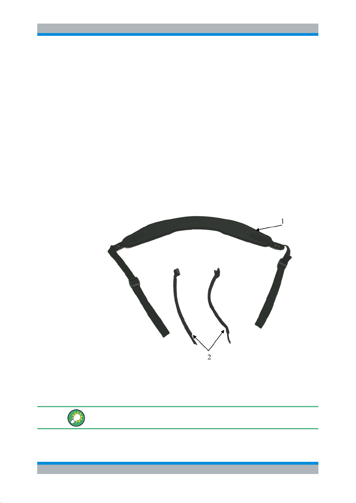
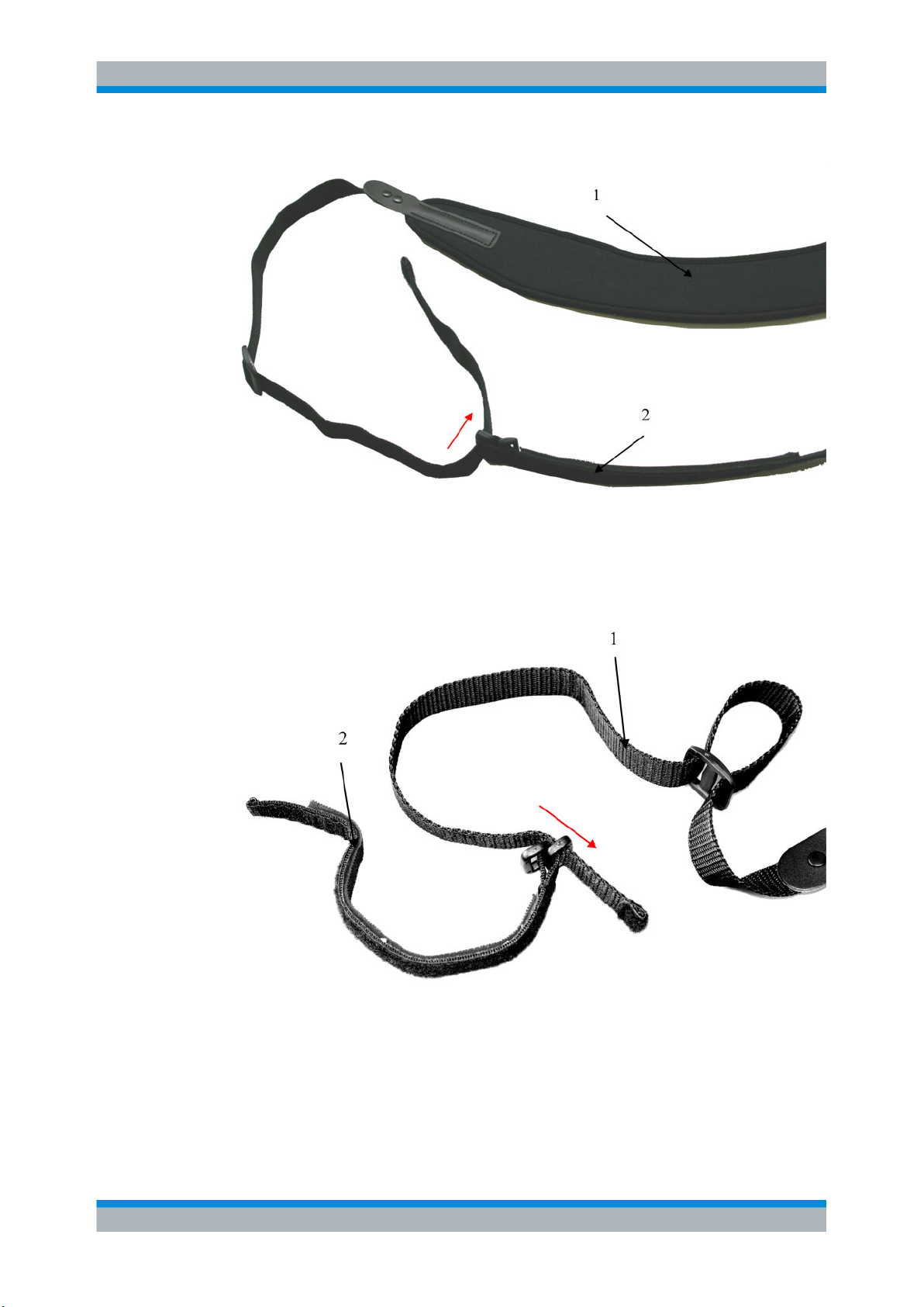
2.2 Assembling the Belt......................................................................................................9
2.3 Attaching the Belt to the Antenna.............................................................................11
3Operation..............................................................................................14
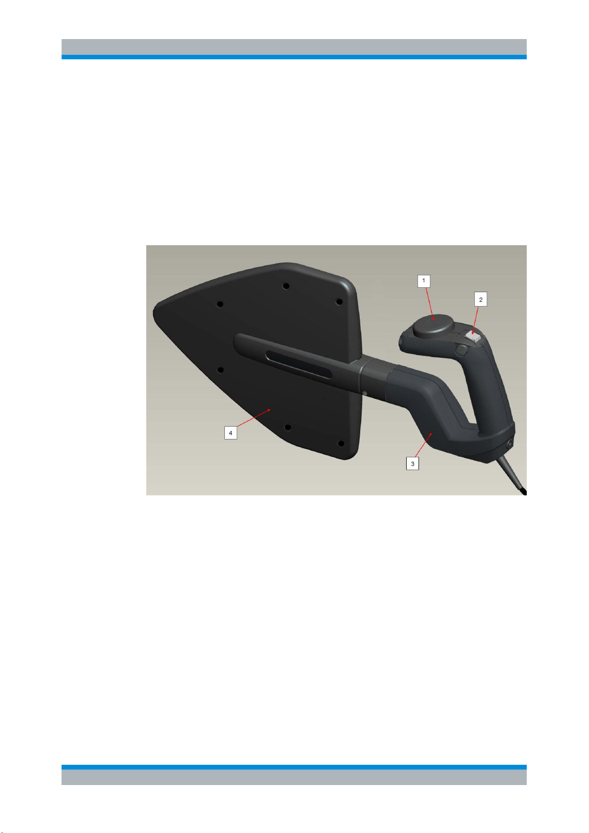
3.1 Operating Elements on the Handle...........................................................................14
3.2 RF and Control Cable.................................................................................................14
3.3 Activating or Deactivating the LNA in the R&S FSH4/8...........................................15
3.4 Notes on Practical Use...............................................................................................16
4Maintenance and Repair......................................................................18
4.1 Maintenance................................................................................................................18
4.2 Disassembly and Reassembly...................................................................................18
4.3 Functional Check........................................................................................................18
4.4 Storage and Transport................................................................................................18
5Diagrams and Patterns........................................................................20
5.1 VSWR...........................................................................................................................20
5.2 Antenna Factor and Practical Gain...........................................................................20
5.3 Radiation Patterns......................................................................................................21
6List of Appendices...............................................................................22

Contents
R&S®HL300
4Manual 4097.3328.02 ─ 01

Characteristics
R&S®HL300
5Manual 4097.3328.02 ─ 01
1 Characteristics
1.1 Use
The handheld log-periodic antenna R&S HL300 in conjunction with portable spectrum
analyzers (for example the R&S FSH4/8) is used to determine RF parameters and local-
ize potential interfering sources. The direction of signal sources is found by pointing the
antenna towards the direction of maximum signal voltage.
Fig. 1-1: R&S
HL300 antenna overview.
1 = GPS/electronic compass unit
2 = toggle switch
3 = antenna handle
4 = log-periodic dipole array
The overall frequency range from 450 MHz to 8 GHz is covered by a log-periodic dipole
array antenna structure with a distinct directional pattern. The antenna does not have to
be tuned within its frequency range.
A built-in GPS receiver with an integrated patch antenna and an electronic compass
provide position and bearing data for further processing in the connected spectrum ana-
lyzer. A toggle switch at the antenna handle activates or bypasses the LNA (Low Noise
Amplifier) inside the R&S FSH4/8, thus allowing the use of the system in the vicinity of
strong transmitters.
The R&S HL300 is characterized by the following features:
●Unambiguous direction finding, i.e. distinct directional pattern with the receive maxi-
mum pointing to the front in the frequency range from 450 MHz to 8 GHz.
Use

Characteristics
R&S®HL300
6Manual 4097.3328.02 ─ 01
●The maximum of the antenna output signal serves as a directional criterion (maximum
direction finding).
●Handy size despite extreme broadband capability.
●Fatigue-free operation due to the antenna design and the material used, which keep
its weight to a minimum.
●Mainly used for vertical polarization but for test purposes horizontal polarization can
also be used by turning the antenna by 90°.
●May be mounted on a tripod (¼” mounting thread).
●Power supply via the connected R&S FSH4/8 through the data and control cable.
1.2 Description
The R&S HL300 comprises the following elements:
●Log-periodic dipole array antenna with a nearly frequency-independent directional
pattern
●GPS receiver and electronic compass
●Toggle switch for activating and deactivating the LNA within the R&S FSH4/8; indi-
cation by adjacent LED
●RF and control cable (length approx. 1.5 m with N-type connector and control con-
nector)
●Tripod mounting thread
A green LED on the rear of the supply and display unit indicates activation of the LNA
within the R&S FSH4/8.
1.3 Specifications
Table 1-1: Electrical specifications.
Frequency range 450 MHz to 8 GHz
Polarization Vertical
(horizontal polarization is also possible when turning
the antenna by 90°)
Nominal impedance 50 Ω
VSWR < 2.5 (500 MHz to 8 GHz)
< 3 (below 500 MHz)
for typical values see figure 5-1
RF connector N-male
Antenna factors for typical values see figure 5-2
Practical gain for typical values see figure 5-2
Directional patterns for typical values see figure 5-3 and figure 5-4
Description

Characteristics
R&S®HL300
7Manual 4097.3328.02 ─ 01
Control connector “Binder” 7 pin male
Supply voltage 5V ± 0.2 V (supplied by spectrum analyzer)
Current consumption max. 100 mA
GPS
Acquisition time
Time pulse frequency
Time pulse accuracy
Navigation update rate
typ. 26s (cold start, all satellites with -130 dBm)
1 Hz
30 ns RMS (under good GPS signal conditions)
1 Hz
Electronic compass
Azimuth coverage
Elevation range
Compass accuracy
0° to 360° in 1° steps
-60° to 60° in 1° steps
typ. 2° RMS for 0° elevation
typ. 4° RMS for ± 60° elevation
Table 1-2: Mechanical and environmental specifications.
Dimensions
max. length
max. width
max. depth
approx. 580 mm
approx. 310 mm
approx. 90 mm
Weight approx. 1 kg (excluding transport bag)
Temperature ranges
Operating temperature range
Nominal temperature range
Storage temperature range
-30 °C to +55 °C (no condensation)
-10 °C to +50 °C
-30 °C to +60 °C
Vibration resistance
according to DIN EN 60068-2-64
random 10 Hz to 300 Hz: 0.01 g2/Hz
300 Hz to 500 Hz: 0.003 g2/Hz
every 30 minutes in the three orthogonal axes; accel-
eration approx. 1.9 g rms
Shock resistance
acc. to DIN EN 60068-2-27 and MIL STD 810 E
max. 40 g, crossover frequency 45 Hz in three orthog-
onal axes
MTBF
according to SN29500, ground benign, 45°C
> 100 000 hours
1.4 Equipment Supplied
Delivery of the R&S HL300 includes:
●1 Handheld Log-Periodic Antenna R&S HL300
●1 transport bag
●1 carrying belt
Equipment Supplied

Characteristics
R&S®HL300
8Manual 4097.3328.02 ─ 01
●1 CD-ROM with manual
●Safety instructions and customer information (print version)
1.5 Recommended Extras
The following extras are recommended:
Designation Order number
R&S FSH4/8 Handheld Spectrum Analyzer 1309.6000.xx
Commercial tripod available in specialist shops
1.6 Ordering Information
Designation Order number
R&S HL300 Handheld Log-Periodic Antenna 4097.3005.02
Recommended Extras

Preparation for Use
R&S®HL300
9Manual 4097.3328.02 ─ 01
2 Preparation for Use
2.1 Use of a Commercial Tripod
The R&S HL300 has a ¼" tripod mount in the lower part of the handle, which is suitable
for attachment to a commercial tripod. The antenna is fastened to the tripod via the tripod's
fastening screw.
2.2 Assembling the Belt
Upon delivery the belt is disassembled. It consists of the following components:
●1 belt
●2 fastening straps
Fig. 2-1: Belt (1) and fastening straps (2).
●Attach the two fastening straps to the belt as shown in figure 2-2, figure 2-3 and
figure 2-4.
Make sure you insert the end of the belt in the plastic fastener facing away from the
neoprene (see red arrow in figure 2-2).
Use of a Commercial Tripod

Preparation for Use
R&S®HL300
10Manual 4097.3328.02 ─ 01
Fig. 2-2: Attaching the fastening strap, step 1.
1 = belt
2 = fastening strap
Fig. 2-3: Attaching the fastening strap, step 2.
1 = belt
2 = fastening strap
Assembling the Belt

Preparation for Use
R&S®HL300
11Manual 4097.3328.02 ─ 01
Fig. 2-4: Attaching the fastening strap, step 3.
1 = belt
2 = fastening strap
2.3 Attaching the Belt to the Antenna
Attach the two fastening straps:
1. Place the handle onto the neoprene sides of the fastening straps, see figure 2-5.
Fig. 2-5: Attaching the belt, step 1.
Attaching the Belt to the Antenna

Preparation for Use
R&S®HL300
12Manual 4097.3328.02 ─ 01
1 = belt
2 = rear fastening strap
3 = handle
4 = forward fastening strap
2. Move the loose end of the straps through the plastic fastener, bend them around and
attach them firmly to the velcro strips, see figure 2-6.
Fig. 2-6: Attaching the belt, step 2.
1 = rear fastening strap
2 = forward fastening strap
2.3.1 Correct Position of the Carrying Belt
When you use the belt, make sure the longer side, i.e. the side with the more pronounced
curve, faces inwards. The neoprene side of the shoulder pad should rest on your shoulder
(see red arrow in figure 2-7).
Attaching the Belt to the Antenna

Preparation for Use
R&S®HL300
13Manual 4097.3328.02 ─ 01
Fig. 2-7: Correct position of the carrying belt: longer side facing inwards, neoprene side resting on the
shoulder.
Attaching the Belt to the Antenna

Operation
R&S®HL300
14Manual 4097.3328.02 ─ 01
3 Operation
3.1 Operating Elements on the Handle
Fig. 3-1: R&S
HL300 operating elements on the handle.
1 = GPS/electronic compass module
2 = status LED
3 = toggle switch
3.2 RF and Control Cable
The RF and control cable protruding from the R&S HL300 connects the antenna to the
R&S FSH4/8 spectrum analyzer. It is approximately 1.5 m long.
The RF and control cable must not be extended beyond a total length of 3 m.
Fig. 3-2: R&S
HL300 RF and control cable.
Operating Elements on the Handle

Operation
R&S®HL300
15Manual 4097.3328.02 ─ 01
Minimum bending radius
The minimum bending radius must be at least 50 mm.
Fig. 3-3: Excessive bending of the RF and control cable will cause permanent damage to the R&S
HL300 .
3.3 Activating or Deactivating the LNA in the R&S FSH4/8
"Passive" mode (bypassing the LNA):
●Move the toggle switch on the handle of the supply and display unit into position "OFF"
(downwards on the handle, see figure 3-4).
"Active" mode:
●Move the toggle switch on the handle of the supply and display unit into position "ON"
(upper position, see figure 3-4). This is indicated by the green LED.
Fig. 3-4: Power label for LNA.
The R&S HL300 should only be switched to "Active" mode if there are no strong trans-
mitters in close vicinity and the sensitivity of the receiving system (antenna with spectrum
analyzer) in "Passive" mode is not sufficient to detect the signal.
Activating or Deactivating the LNA in the R&S FSH4/8

Operation
R&S®HL300
16Manual 4097.3328.02 ─ 01
The toggle switch remains in its position ; to deactivate the LNA move the switch back
into position “OFF”.
3.4 Notes on Practical Use
3.4.1 How to hold the R&S HL300
To ensure optimum DF results, you have to carry the R&S HL300 with your arm stretched
out for locating the maximum.
Fig. 3-5: Manual direction finding by locating the maximum.
The center of rotation should be located in the antenna rather than your body. Moving
the antenna to and fro is unfavorable since the search for maximum reception is impaired
by site-dependent level differences occurring in disturbed electromagnetic fields.
Notes on Practical Use

Operation
R&S®HL300
17Manual 4097.3328.02 ─ 01
If an unambiguous maximum is not obtained in a closed room, for example, the interfer-
ence due to reflections is too high and the site has to be changed.
Reflections and interference occur if electromagnetic waves come into contact with
objects that have a high dielectric constant or are conductive.
In a disturbed environment, direction finding should best be carried out from several sites,
approaching the source gradually (see figure 3-6).
Fig. 3-6: Locating a source in a disturbed environment, for example inside a room.
Notes on Practical Use

Maintenance and Repair
R&S®HL300
18Manual 4097.3328.02 ─ 01
4 Maintenance and Repair
4.1 Maintenance
The R&S HL300 is maintenance-free.
4.2 Disassembly and Reassembly
Disassembly and reassembly
Any disassembly/reassembly must be performed by skilled and authorized technical per-
sonnel observing the regulations for electrostatic sensitive devices.
4.3 Functional Check
If the green LED above the toggle switch does not light up when you activate the LNA,
there is a potential problem with the connection to the R&S FSH4/8 spectrum analyzer.
In order to verify the connection:
●check the control cable connector
●check the settings of the R&S FSH4/8.
4.4 Storage and Transport
The R&S HL300 should only be stored and transported in the supplied transport bag.
Make sure that the RF and control cable is bent towards the front of the antenna. Attach
the R&S HL300 with the velcro fastener inside the bag in order to avoid exceeding the
allowed bending radius of the cable (see figure 4-1 and "Minimum bending radius"
on page 15).
Maintenance

Maintenance and Repair
R&S®HL300
19Manual 4097.3328.02 ─ 01
Fig. 4-1: R&S
HL300 transport bag.
1 = velcro fastener
Storage and Transport

Diagrams and Patterns
R&S®HL300
20Manual 4097.3328.02 ─ 01
5 Diagrams and Patterns
5.1 VSWR
Fig. 5-1: R&S
HL300 typical VSWR.
5.2 Antenna Factor and Practical Gain
Fig. 5-2: R&S
HL300 typical antenna factor and practical gain.
VSWR
This manual suits for next models
1
Table of contents
Other Rohde & Schwarz Antenna manuals
Popular Antenna manuals by other brands

ImmersionRC
ImmersionRC 5.8GHz SpiroNET 13dBi instruction manual

One Forall
One Forall 17411 Quick installation guide

Sirio Antenne
Sirio Antenne SU 370-490 installation manual

Maco Antennas
Maco Antennas Y-QUAD Assembly instructions

Megasat
Megasat Profi-Line II D1 manual

Teleco
Teleco Flatsat Classic Easy Installation guide and user's manual

August
August DTA225 user manual

UPS Aviation Technologies
UPS Aviation Technologies Apollo A-34 installation manual

HDView360
HDView360 Mini-State HDMS9100 instruction manual

CUSHCRAFT
CUSHCRAFT A50-6S Assembly & installation

Antenna Pros
Antenna Pros AX-912 manual

Hemisphere GPS
Hemisphere GPS S321 Non-UHF user guide