Rohde & Schwarz HE 100 User manual

m>>
u. (
(D en
01 E
Ll_ 03
CI) n
J_ n
ro
CD 5
C Q.
a. cr
\;. •
- I
HANDBUCH MANUAL
AKTIVE RICHTANTENNE
HE 100
ACTIVE DIRECTIONAL ANTENNA
HE 100
701.5002
r: -- ' ^--.r- ■■ - V •..;/■>.::,
701.5002
Bestell-Nr./Order No.: 652.1803.02

The Active Directional Antenna HE 100 from Rohde & Schwarz meets
all the requirements a modern, hand-held DF antenna should fulfil:
- Unambiguous determination of direction of incidence, i.e.
distinct directional pattern
- Antenna voltage maximum as direction criterion (maximum-signal
DF method)
- Handy size, in particular minimum crosswise dimensions, and low
weight
- Suitability for vertically and horizontally polarized signals
- Wide dynamic range due to selectable sensitivity permitting use
even in extremely intense electromagnetic fields
- Low current drain
H E 1 0 0 R 4 4 4 1 1 - 1 R O H D E & S C H W A R Z
C^i
(^

WI
*FI
wi
WI
S)
i*j
<$£)
W
(WI
Contents
j U s e s . . . . 3
2 Description 3
3 Operation 4
4 P r a c t i c a l H i n t s • 5
5 S p e c i fi c a t i o n s 6
5 . 1 E l e c t r i c a l S p e c i fi a t i o n s 6
5 . 2 M e c h a n i c a l S p e c i fi c a t i o n s 7
5.3 General Data ........ 7
6 Equipment Supplied .7.
7 Maintenance 8
H E 1 0 0 R 4 4 4 1 1 - 2 R O H D E & S C H W A R Z

1 Uses
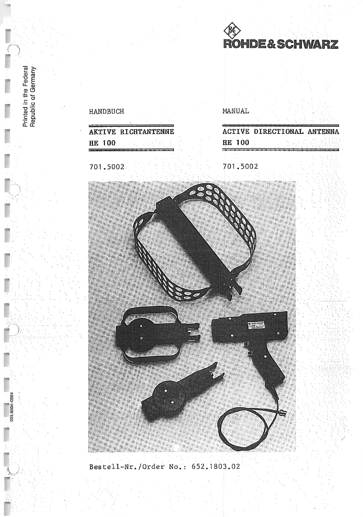
Due to its small size and low weight, the Active Directional
Antenna HE 100 in conjunction with a compact, portable receiver
(e.g. EB 100) is ideally suited for tracing signal sources and
sources of interference.
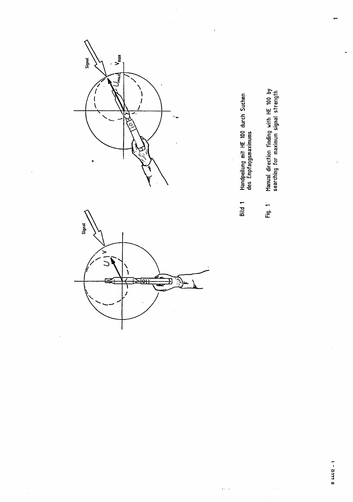
The direction of the signal source is found by pointing the an
tenna towards the direction of maximum signal voltage. The
overall frequency range from 20 to 1000 MHz is covered by three
exchangeable antenna modules, which handle both vertically and
horizontally polarized signals and have almost identical cardioid
radiation patterns in both planes.
In order to increase the sensitivity, a low-noise amplifier can
be switched into circuit (active/passive switchover). As this
amplifier is bypassed during passive operation, the HE 100 can
also be used in the vicinity of powerful transmitters.
Camouflaged use of the antenna, for instance in a suitcase or a
travelling bag, is also possible.
2 Description .
The broadband, cardioid directional pattern of the HE 100 is
obtained by using loaded loop antenna modules of different size
for the three subranges of 20 to 200 MHz, 200 to 500 MHz and 500
to 1000 MHz. These RF modules can be plugged on to a handle,
which contains the following:
- Power supply, which comes from a set of four round cells R6
(dry or NiCd cells) contained in a removable battery holder.
- Antenna electronics, comprising RF amplifier, active/passive
switch and circuitry for the meter.
In the active mode, the RF signal path is taken via an RF relay
(when supply voltage is switched on) to the low-noise amplifier,
which is bypassed in the passive mode.
- Meter, which indicates the strength of the incoming signal. The
pointer deflection is controlled by the receiver via the RF
cable. The meter, which can be illuminated, also indicates the
state of the batteries at the push of a button.
H E 1 0 0 R 4 4 4 1 1 - 3 R O H D E & S C H W A R Z

"51
*UI
3 Operation
(see drawing 701.5002.01)
a) Replacing RF modules:
Release catch by pressing two studs (2) and pull out RF module
Plug in required RF module until it locks in position.
b) Active/passive switchover:
Select the desired mode by means of pushbutton (3).
c) Meter indication of state of battery:
Press pushbutton (8) for the battery test on the meter; red
marking: battery discharged.
d) Meter illumination:
The illumination is switched on by pressing pushbutton (4).
e) Replacing battery:
Open the cover (7) of the battery compartment and replace bat
teries in holder.
H E 1 0 0 R 4 4 4 1 1 - 4 R O H D E & S C H W A R Z

P r a c t i c a l H i n t s _
In order to obtain optimum results, hold the antenna with the arm
fully stretched out to find the signal maximum. The centre of
rotation should go through the antenna (see Fig. 1) to make sure
that any variations in signal strength caused by disturbances of
the electromagnetic field due to local influences do not impair
the measurement.
If it is not possible to find a pronounced maximum, the effect of
reflection s is too great. Such re flec tions or interfer enc e are
caused whenever electromagnetic waves hit large objects with a
hig h diele ctri c cons tant or good el ectr ical c onduc tivi ty.
It is advisable to take bearings from several points, gradually
coming closer to the transmitter (see Fig. 2).
|™|
fmUl
H E 1 0 0 R 4 4 4 1 1 - 5 R O H D E & S C H W A R Z

WI
ml
m\
«5I
5 Specifications
5.1 Electrical Specifiations
F r e q u e n c y r a n g e 2 0 t o 1 0 0 0 M H z c o v e r e d b y t h r e e
RF modules:
20 to 200 MHz with
RF module 701.5702
(50) 200 to 500 MHz with
RF module 701.5354
(100) 500 to 1000 MHz with
RF module 701.5554
The extended frequency ranges
specified in parentheses are
covered with reduced sensitivity,
C h a r a c t e r i s t i c i m p e d a n c e . . . . 5 0 a
R F c o n n e c t o r B N C
P o w e r s u p p l y f o u r d r y c e l l s R 6 1 . 5 V * )
(contained in handle)
C u r r e n t d r a i n D r y c e l l s ( 6 V )
Passive operation 0 mA
Active operation 47 mA
Meter illumina
tion 30 mA
B a t t e r y t e s t 1 2 0 m A
Antenna factor
K = 2 0 l o g E / V o u t s e e F i g . 3
Field-strength sensitivity
(for receiver noise of 10 dB
a t b a n d w i d t h o f 7 . 5 k H z ) s e e F i g . 4
Radiation patterns . H plane: cardioid
E plane: cardioid
see Fig. 5
*) The dry cells supplied with the HE 100 can be replaced by
ordinary rechargeable NiCd cells (4 x 1.2 V, 0.5 Ah, size
R6) with charger.
H E 1 0 0 R 4 4 4 1 1 - 6 R O H D E & S C H W A R Z

5.2 Mechanical Specifications
Resistance to vibration
( i n t r a n s p o r t c a s e ) D I N / I E C 6 8 - 2 - 6
(5 to 55 Hz, 0.2 mm amplitude)
R e s i s t a n c e t o s h o c k D I N / I E C 6 8 - 2 - 2 7
(half sinus, 30 g, 11 ms)
Degree of protection ...... IP 54 (in position of use)
5.3 General Data
Dimensions see drawing 701.5002.02
T r a n s p o r t d i m e n s i o n s 4 7 0 m m x 3 6 0 m m x 1 8 0 m m
(outer dimensions of transport
case)
Length of cable 1.2m
Weight handle with RF module
701.5554: approx. 0.8 kg
'701.5354: approx. 0.8 kg
701.5702: approx. 1 kg
Total weight including
transport case ......... 4,5 kg
Operating temperature range . . . -30 C to +50 C
Storage temperature range .... -30°C to +60°C
6 Equipment Supplied Order No.
Handle (containing power supply
and display module) 701.5019
3 RF modules 701.5702
701.5354
701.5554
4 dry cells, size R6 (1.5 V)
1 transport case 701.5860
1 manual 652.1803.02
* r \ * % i - » / / / ■* 4 ROHDE&SCHWARZ

7 Maintenance
If the batteries used are not leakage-proof, check the battery
container at regular intervals.
^
^i
^u
^5J
^&l
r^t)
H E 1 0 0 R 4 4 4 1 1 - 8 R O H D E & S C H W A R Z

QJ
JZ
t/1
2 w
^ E
uj E
j_ ro
E w
en
en c-
c r o
3 »»-
r=f Q.
£ E
Q.LU
C W
ro oj
X - o
2. £
UJ t/i
j z r o
-t <=
to
en
c E
•^ *x
ro
c c
o
•o en
P
£ ro

Bild 2 Sendersuche In einem geschlossenen Raum mit
starken Storungen des elektromagnetischen Feldes
Fig. 2 Tracing a transmitter in- a room with heavily
disturbed electromagnetic field
HE 100

CD
SUJ
QjmuJHcd
rSjhbh
KHQihlil
HKHtUCQ
HIUHbitQ I
UiCQlUCQ I >
9 mimi>h
S I > I >HOT
m>H>HHW
HWH«Si<
<Q.<£LNN
O NMNNSI
O X X X X
N SXXXOO
(9(9
OQOOQS
QOSI9-'-
CMNIOIO I I
I I I I 6)6)
ra OQQOC3C3
g CMCMIOIO- —
** _1_1JJJJ
333333
OOOOOO
OOOOOO
XXXXXX
<o
3>
\N.
UJ UJ
en en
o o
—* —*
ca o
CNJ OJ
II II
J£ i<£
(_ «_
Oo
•4—
•SC u
ro ro
»*- M—
rz
OJ ro
cc
cc
OJ OJ
•t—
c c
<.. <
ri en
CD u_
G> ^NtOTWO
10 CO to 0) u> G) U) Q
in U)
£Q
Q
N
it
T V CO CO CM CM 10
u Q.
<
3 C O U J
■OUJg
5 oc t-
*. I— UJ
„ uj aa
" <a j
- j J >
a i— i/i
o b£ <
Z < Q .

X
> 1 0 G >
3 C O C O
N
CO
o
10 CO
10
to ca
G > C Q I l l
T m C Q I U H
(Q UJ £0 UJ H OS
lUHUHttt-
HQJHQJHUI
huihuicq i
S o q i m i > h
S I > I > H C O
n>H>HhW
HWH(0 2*<
r-W»-W<Q.
<Q.<Q.NN
CO NNNNXX
CO XXXX
C M X X X X C O O
COCO
SX9C9C0 CO 6)
COCOCOCOo- —
( M f M U ) U ) I 1
I I I I C O C O
fa CO CO CO CO CO CO
§ CMCMIOtO-*-
*" JJJJJJ
333333
OOOOOO
OOOOOO
XXXXXX
(9
— NCOVIOCO
01 -b *
II
!£ ro
S <u ±:
oj cn'oj Z
u ~ c c _ \
m :ro jq ,/J
* » 9 - c t _
c_ E ro ..5
U UJ CD C.
2
5
_cn n
X: .« tn —.
cn'o t-^ *~
S c - i i
u a 5 ' ■
•!
01 -K
.£ ">
j_ ro
ti
J S c a
3IDU
5 o: h-
„ uj ca
" ca i
o (- «/i
o ie: <
r < o.

160*
JOO"
Bild 5 Typisches Richtdiagramm der Aktiven Richtantenne HE100
Fig. 5 Typical directional pattern of HE 100

in
\
3'
13 01
ro-*
3c"Z n>* " e
O
<ll |
N e
en
c
_3
"qJ
c_
ro
a_
<» § N
S " S J . - a
in§ TI Si
i 2 0 2 , I
o
CM
■of -a J2 -a "
O = O 3 O =
i . o 2 . o X o
I E I E | E
LL.i IJ-uL LLul
^ ~ X k X o c
en
c
3
t_
JZ
-.3
M—
VI
ZD
ro
-o-.
c: "3
2°
ii H
51
M?
<PC
N
^£
o S
O O
o °
«0 OJ
2 =
■*■—OJ
£ .s
T3
OJ
a . > >
i <
i^
O
csi
o
o
in
n
(»SiE 63 / 00E '"
J* .a
"> "*s
™ .E
°-E
re .£ u
»-» ■*-J_
cu ra g
u : c
re
Li o a
o « » - -
U c c
C V O J o o
Satt
S2Ja-S■-
E r £ a i
<-J ' !fl !2 -f
ii ti ii ii ii
"H J"5 fn -J- in
"«/» en
m c
ro a
\£
> 3
j - a i
< - Q
en aj
3 C
•*-• m
ro E
x; s
u c
V) •* -
(Z t/J
*•— f—
tu
a*
u •»■— JJ
O J l / J W N
e_ ro ro C
I — I — i — <
II II II II
a. u
E o»
o ~
Of
-se; iS JE
i<u ai .£'
JC o
u j c
oj ai
Otd
l r o
.2—'
OJ ai
■4-If]
ro ro
en H-
r-Nm«tm
0(1(38"
nn aBn..
1 sunjt"
. asm..
/A\

■"3S1
«-• a
b i
NOg g
—i r*
"■5CMS
Q-CO 5
3 in ^
rn"8*5 |
<2PI
"Tl
x
Z
;1_J I ( »
"^"1
pUl
a
JC
to
J3
OJOJ
«
"C
0
c
:j
0
0
■5
I 5
■■fl
"""il
*"SI
"SI Bild: 13
3313 A
And
ZusL Anderungs-
Mitteilung
02M
Tog
ifc
Nome
Md
Bearb.
Gepr.
Norm
Tog
02.86
Name
Ha.
ROHDE&SCHWARZ
Gerat: HE 100
Benennung
Aktive Richianienne UE100
Zeichn.-Nr.
701 5002 T
r e g i V. W 1 . S 0 0 2 V l e r s t e Z T
BloH-Nr.
1S
Bl.
DcroBTwo.innfi

ROHDE&SCHVVARZ
AZ Datum
Date
08 0386
Schaltteilliste fur
Parts list for
HE100 AKTIVE RICHTANTENNE
HE100 ACT.DIR.ANTENNA
Kennzeichen
Component No.
Al
A2
A3
AA
C1
C2
C3
61
BIS/TO
64
H1
K1
L1
PI
RI
R2
R3
Benennung/Beschreibung
Designation
ZUGEH.STROML./CIRC.DIAGR.
701-5002 S
ED HODULPLATINE I
HIERZU STROML. 701.5002 S
ED MODULPLATINE II
HIERZU STROML. 701.5002 S
ED MODULPLATTE III
HIERZU STROML. 701.5002 S
ED ANTENNENELEKTRONIK
HIERZU STROML. 701.5002 S
CC 2,2NF+-10%5X6R2000
CAPACITOR
VALVO
CC 2,2NF+-
CERAMIC CH
VITRAMON
CC 2,2PF+-
CAPACITOR
VALVO
2222 63051 222
10%50VX7R 1206
IP CAPACITOR
VJ1206Y222KFA
Q,25PF3X4NP0
Sachnummer
Stock No.
701.5002.01 sa
Sachnummer
Stock No.
2222 678 09228
EB 1,5V RUNDZELLE R6 MIGN
BATTERY
DURACELL MN1500
EF W2X4,6D 6-7V 30 MA I
INCANDESCENT LAMP
ALBA A-812-3K-2 MIT SOCK.
ENTHALTEN IN
701.5177
SN T05 6V 2XUM
RELAY
TELEDYNE-R 732-6
LD 5,60UH10X1,800HMO,195A
CHOKE
DELEVAN DROSSEL1025-38
JK 1MA 39X14U 350 OHM
INSTRUMENT
A M S N . R S S - Z C H N 6 . 7 0 1 . 5 ) 7 7
RL 0,35W 1,50KOHM+-1%TK50
RESISTOR
DRALORIC SNA0207/1,50K-F-D
RS 0,5U 1K0HM+-20XKURVE1
DEPOS.-CARBON POTENTIOMET
BOURNS 3329H-1-102
RL 0,65W 47,5 OHM+-1ZTK50
METAL FILM RESISTOR
RESISTA MK4 47,5 OHM 1% Tfc5 0
701.5602.02
701.5454.02
701.5802.02
701.5202.02
CC 087.7060
CC 099.8444
CC 087.6341
EB 017.0109
EF 019.2644
549.2447
LD 067.2957
701.5177
RL
RS
083.0732
069.8030
006.1867
Bfatt
Page
701.5002
enthalten in
contained in
701.5554
701.5354
701.5702
701.5019
701.5202.01
701.5202.01
701.5202.01
701.5019
701.5202.01
701.5202.01
701.5019
701-5202.01
7C1.5202.01
701.5202.01
01 SA BL 1+

<$>
AZ Datum
Date Schaltteilliste fQr
Parts list for Sachnummer
Stock Na Bfatt
Page
ROHDE&SCHWARZ HE100 AKTIVE RICHTANTENNE
08 0386 HE100 ACT.DIR-ANTENNA 701.5002.01 SA 2
Kennzeichen Benennung/Beschreibung Sachnummer enthalten In
Component Na Designation Stock No. contained in
R4 RS 0,5W 5KOHM+-20XKURVE1
DEPOS.-CARBON POTENTIOMET
BOURNS 3329H-1-502
RS 069.8052 ' 701.5202.01
R5 RG 10,0 0HM+-2XTK2Q0 1206
CHIP -RESISTOR
RG 006.8649 701.5202.01
DRA L O RIC CGB32 1 6 1 00HM2X T K ? 00
R6 RG 10,0 OHM+-2XTK20Q 1206
CHIP -RESISTOR
RG 006.8649 701.5202.01
DRALORIC CGB3216 100HM2XTK.I00
R7 RG 178 OHM+-2XTK20Q 1206
CHIP RESISTOR
D R A L O R I C C G B 3 2 1 6 1 7 8 0 H M 2 X ' K
R6 006.8949 701.5202.01
R8 RL O-WIDERSTAND DIN 0204
O-OHM RESISTOR
DRALORIC OMA 0204
RL 069.0000 701.5202.01
R10 RL 0,21W 220 0HM2X UNGEU.
RESISTOR
RL 092.5991 701.5602.01
R E S I S TA M K 1 2 2 0 0 H M 2 X U N G ;w ■
, R20 RL 0,21W 301 OHM+-1XTK50
RESISTOR
R E S I S T A M K 1 3 0 1 0 H M t t T K 5 ( I
092.0183 701.5454.01
R30 RL 0,21W 301 OHM+-1XTK50
RESISTOR
R E S I S T A M K 1 3 0 1 0 H M 1 X T K 5 I
092.0183 701.5802.01
SI SB DRUCKTASTE 1XU. LOETANS
PUSH-BUTTON SWITCH
APR R&S-ZCHNG.701.596!>
701.5960 701.5019
S2 SB DRUCKTASTE 1XU LOETANS
PUSH-BUTTON SWITCH
APR R&S-ZCHNG.701.5961I
701 .5960 701.5019
S3 SB DRUCKTASTE 2XU LOETANS
PUSH-BUTTON SWITCH
APR R&S-ZCHNG.7015977
701.5977 701.5019
T10 LU UEBERTRAG. 500-1000MH2 701.5790 701.5602.01
T20 LU UEBERTRAGER 200-500MHZ 701.5783 701.5454.01
T30 LU UEBERTRAG.20-200HHZ 701.5777 701.5802-01
V1 BD YAM-104 10DB/0,Q2-1,36 914.3605.02 701.5202.01
: V2 A E B Z X 7 9 / C 3 V 9 0 , 5 W Z - D I
ZENER DIODE
VALVO BZX79/C3V9
AE 086.8234 701.5202.01
V3 A E 5 0 8 2 - 2 8 0 0 S C H O T T K Y D I
DIODE
HEWLETT-P. 5082-2800
AE 012.9066 701.5202.01
W1 DX HF-KABEL CW1) 701.5248 701.5019
W2 DX HF-KABEL <W2) 701.5254 701.5019
W10 DX H F - K A B E L C U 10) 701.5625 701.5602.01
U2Q DX HF-KABEL ( W 2 0) 701.5477 701.5454.01
U30 DX HF-KABEL CW30) 701.5825 701.5802.01
x.1 FJ EINBAUSTECKER SYST.SHB
PLUG
S O C A P E X S X 0 2 B . 2 0 0 5
FJ 063.5168 701.5202.01
•701.5002 ,01 SA BL 2+

r
ROHDE&SCHWARZ
Kennzeichen
Component Na
X2
X3
X4
[^1
$T$iJ
~4-
JO
qff.B
>"S
"5 •
51
AZ Datum
Date
08 0386
Schaltteilliste fur
Paris list for
HE100 AKTIVE RICHTANTENNE
HE100 ACT.DIR.ANTENNA
Benennung/Beschreibung
Designation
FJ EINBAUSTECKER SYST.SMB
PLUG
S O C A P E X S X 0 2 B . 2 0 0 5
FP STECKERLEISTE 16P0L
CONNECTOR 16P0L
BERG 75844-102-16
FP STECKERLEISTE 12POL
CONNECTOR 12P
BERG 75844-102-12
Sachnummer
Stock No.
701.5002.01 sa
Sachnummer
Stock No.
FJ 063.5168
FP 701.5225
FP 701.5231
r»SJ
*sin
iwi
^i|
Bfatt
Page
enthalten in
contained in
701.5202.01
701.5202.01
701.5202.01
- ENDE -
701.5002 ,01 SA BL 3-
Table of contents
Other Rohde & Schwarz Antenna manuals
Popular Antenna manuals by other brands

MFJ
MFJ MFJ-1982LP instruction manual

ZENEC
ZENEC Z-EACC-DAB2 installation manual

Sennheiser
Sennheiser A 1031 U Instructions for use

TerraWave Solutions
TerraWave Solutions T24140P1000690 instructions

Directive Systems & Engineering
Directive Systems & Engineering DSE3311LYRM Assembly instructions

Retro Antenna
Retro Antenna WPA1 installation guide