manuals.online logo
Brands
  1. Home
  2. •
  3. Brands
  4. •
  5. Rohde & Schwarz
  6. •
  7. Media Converter
  8. •
  9. Rohde & Schwarz GC 003 User manual

Rohde & Schwarz GC 003 User manual

This manual suits for next models

1

Other Rohde & Schwarz Media Converter manuals

Rohde & Schwarz ZVA-Z90E User manual

Rohde & Schwarz

Rohde & Schwarz ZVA-Z90E User manual

Rohde & Schwarz ZVA-Z75 User manual

Rohde & Schwarz

Rohde & Schwarz ZVA-Z75 User manual

Rohde & Schwarz TSME30DC User manual

Rohde & Schwarz

Rohde & Schwarz TSME30DC User manual

Rohde & Schwarz R&S User manual

Rohde & Schwarz

Rohde & Schwarz R&S User manual

Rohde & Schwarz RT-ZF6 User manual

Rohde & Schwarz

Rohde & Schwarz RT-ZF6 User manual

Rohde & Schwarz SGU100A User manual

Rohde & Schwarz

Rohde & Schwarz SGU100A User manual

Popular Media Converter manuals by other brands

TR-Electronic CMS582M-4096/4096 IOL DMS 14H7 KRF Assembly instructions

TR-Electronic

TR-Electronic CMS582M-4096/4096 IOL DMS 14H7 KRF Assembly instructions

Korenix JetCon 2301S user manual

Korenix

Korenix JetCon 2301S user manual

StarTech.com ET91000LCOAM manual

StarTech.com

StarTech.com ET91000LCOAM manual

Alesis AI-3 Reference manual

Alesis

Alesis AI-3 Reference manual

Caton Vpro 5100 user guide

Caton

Caton Vpro 5100 user guide

Cypress CSC-5500 Operation manual

Cypress

Cypress CSC-5500 Operation manual

H&B TX-100 Installation and instruction manual

H&B

H&B TX-100 Installation and instruction manual

Bolin Technology D Series user manual

Bolin Technology

Bolin Technology D Series user manual

IFM Electronic Efector 400 RN30 Series Device manual

IFM Electronic

IFM Electronic Efector 400 RN30 Series Device manual

GRASS VALLEY KUDOSPRO ULC2000 user manual

GRASS VALLEY

GRASS VALLEY KUDOSPRO ULC2000 user manual

Linear Technology DC1523A Demo Manual

Linear Technology

Linear Technology DC1523A Demo Manual

Lika ROTAPULS I28 Series quick start guide

Lika

Lika ROTAPULS I28 Series quick start guide

Weidmuller IE-MC-VL Series Hardware installation guide

Weidmuller

Weidmuller IE-MC-VL Series Hardware installation guide

Optical Systems Design OSD2139 Series Operator's manual

Optical Systems Design

Optical Systems Design OSD2139 Series Operator's manual

Tema Telecomunicazioni AD615/S product manual

Tema Telecomunicazioni

Tema Telecomunicazioni AD615/S product manual

KTI Networks KGC-352 Series installation guide

KTI Networks

KTI Networks KGC-352 Series installation guide

Gira 0588 Series operating instructions

Gira

Gira 0588 Series operating instructions

Lika SFA-5000-FD user guide

Lika

Lika SFA-5000-FD user guide

manuals.online logo
manuals.online logoBrands
  • About & Mission
  • Contact us
  • Privacy Policy
  • Terms and Conditions

Copyright 2025 Manuals.Online. All Rights Reserved.

M&SCHWARZ
.
?¢ther
uh:
$43.3,“an
Egmcwb
0:“
5
@3th MANUAL
STEREOCODER
GO 003
230.8518
mammmz<
co>
mszfimmhmnb
.
:owfianQQmMmsxw
w—a an- AR
Table of Contents
Data sheet
2. Pregaration for Use and 02erating Instructions ............. ..... 5
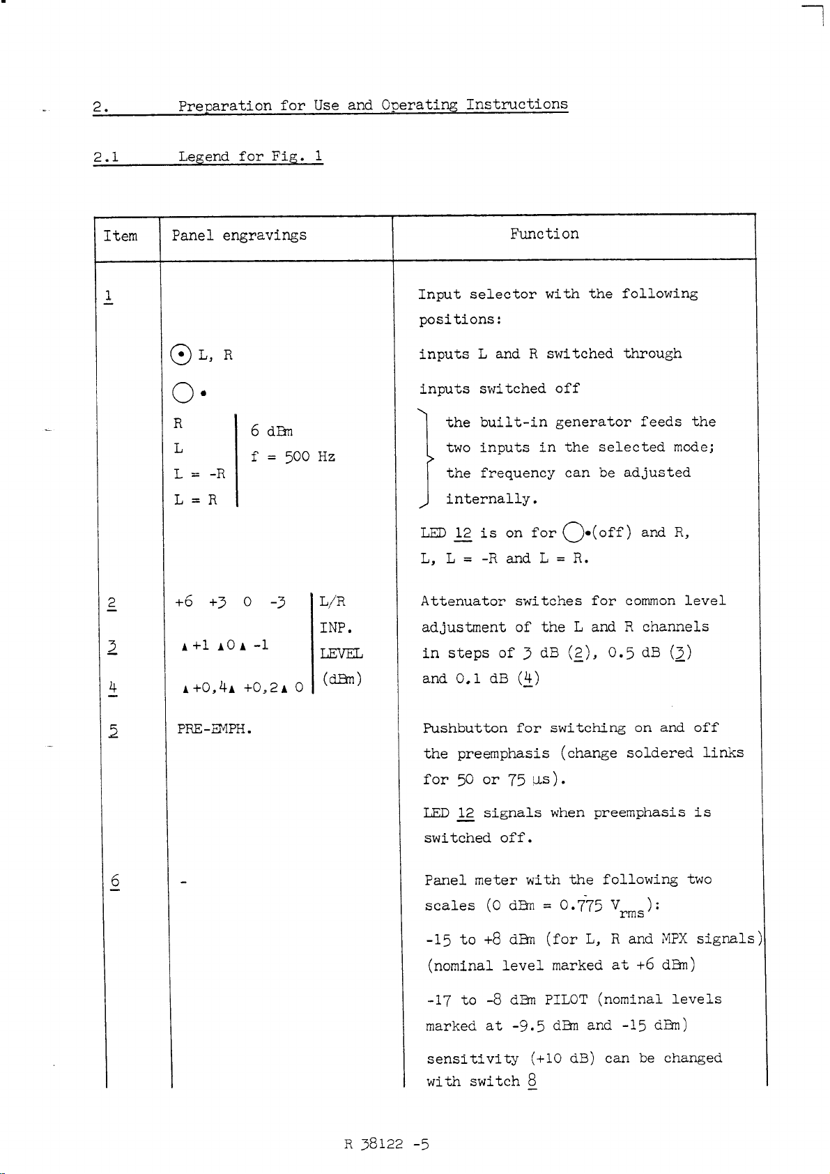
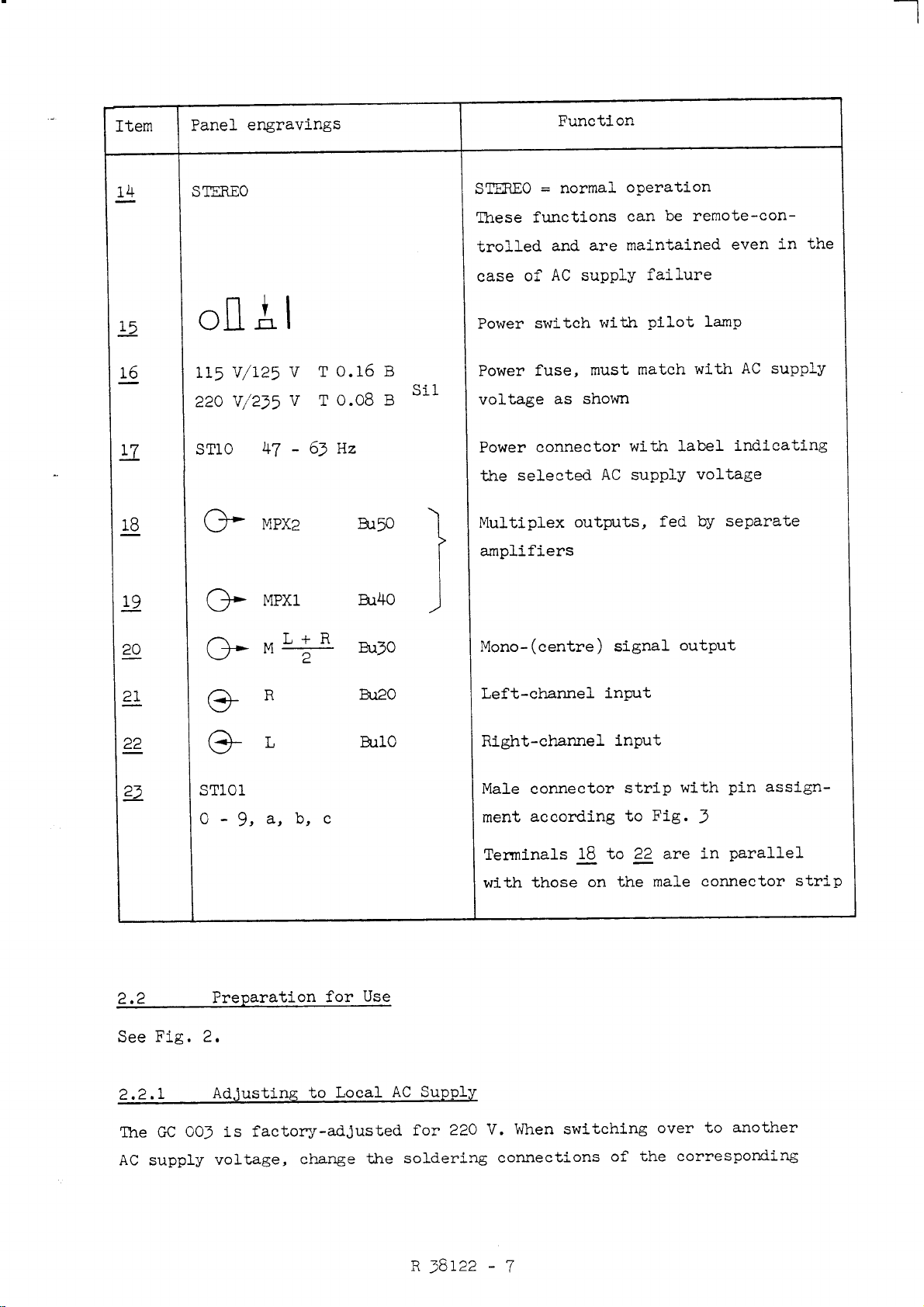
2.1 Legend for Fig. l............................... ..... . ....... ... 5
2.2 Preparation for Use ............................................. 7
2.2.1 Adjusting to Local AC Supply ......................... ........ ... 7
2.2.2 Adjusting the Preemphasis (L and R) and
Deemphasis (M =LgR).......................................... 8
2.2.3 Input Resistance .................. ..... ........... .............. 8
2.2.4 Changing to Operating Mode MONO .... ...... ...... .............. ... 8
2.2.5 Synchronization to External Pilot Tone .............. .... ...... .. 8
2.2.6 Fitting the SCA Modulator (option) ............ ..... .... ......... 8
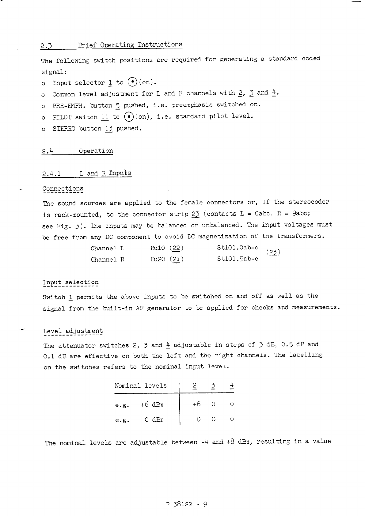
2.3 Brief Operating Instructions ..... ..... ... ............ ........... 9
2.4 Operation .. ....... .......... ...... .............................. 9
2.4.1 L and R input .... ..... .......... ........... .. ..... . .......... .. 9
2.4.2 MPX land MPX 2 Outputs ............. ......... ................... 10
2.4.} MOutput ..... ..... .............. ..... .... ..... .. ...... . ...... ... 11
2.4.4 Stereo/Mono Switchover ............. .................. ........... 11
2.4.5 Pilot Tone ........... ..................................... ...... 12
2.4.6 Auxiliary Inputs ................ ...... .................. ........ l3
3. Maintenance .................................................... 14
3.1 Routine Maintenance ................. ....... ... .................. 14
3.2 Checking the Rated Specifications ............................... 14
3.2.1 Required Measuring Equipment .......... ................. ... ...... 14
3.2.2 Measurements ......... ......................... ..... ............. l4
4. Circuit Descrigtion .. ..... .................. .................... 17
4.1 Land RChannels ......... . ...................................... 17
4.2 Coder ... ........................................................ 17
4.3 Summing Amplifier, MPX Lowpass Filter and Output
Amplifier ........ ........ ............... ....... . ....... . ...... .. 18
4.4 Pilot—frequeney Processing .................... .................. 19
4.5 AF Generator ............................................ ........ 20
4.6 Indication ... .................. .. ...... ...... ................... 21
4.7 Selection of L or RChannel for Mono ............................ 21
R38122 -3
4.8 Power Supply ...
5. Repairs ........
5.1 Required Measuring Equipment ...........
5.2 Trouble-shooting ........................
IaooolonoootInocclnooouo-I
aoolitnllnalllnao
nguo-nuoco-o:oo-nacoooo-n. .....
.....Ialoooloono
......
5.2.1 Power Supply ...................................................
5.2.2 AF Generator, Input Amplifier, L/R and L +R
Indication ....
5.2.3 Generation and Processing of Pilot Tone ........... .
5.2.4 -Coding and Output Amplifier ..
5.3 Adjustments .............................
5.3.1 Supply Voltages ..................
5.3.2 AF Generator ........................................
oo-oo.co-ooaanoo...--cu.oooo
Iainooao-oouc-oooono-uoa
no-ona-ooooo-a
...o-ooan
IIIOIICDIDIOIIIIOIIIDIIIOIIO
5.3.3 Indication .....................................................
5.3.4 Channels Land R...-..c-no-ooooon-ooogno IJ-olouo
5.3.5 MPX Lowpass Filter and Output Amplifier .........
5.3.6 Pilot-tone Generation ..........................................
5.3.7 Crosstalk L/R ..................................................
5.3.8 Crosstalk M/S ..................................................
Interior view
Pin assignment
1
2
3
Fig. 4Preemphasis
5Level diagram
6
Front— and rear-panel controls
Oscillograms Pilot—tone generation
Fig. 7Oscillograms Coder circuitry
Translations for Drawings and Diagrams
Drawings and Diagrams
R38122 —4
noun.-
23
23
23
25
25
23
24
24
24
24
25
25
25
26
28
28
2. Pre aration for Use and Operati Instructions
2.1 Legend for Fig. 1
IW
L:
Kn
®L,R
O
R6dBn
Lf=500 Hz
L=—R
L=R
+6 +3 0-5 L/R
INP.
”1 ‘0‘ ‘1 LEVEL
(dEm)
A+O,4A +O,2A O
PRE—EMPH.
Input selector with the following
positions:
inputs L and Rswitched through
inputs switched off
the built—in generator feeds the
two inputs in the selected mode;
the frequency can be adjusted
internally.
LED ;_2_is on for Q-(off) and R,
L, L=-Ra_ndL=R.
Attenuator switches for common level
adjustment of the Land Rchannels
in steps of 3dB (2), 0.5 dB (2)
and 0.1 dB (5)
Pushbutton for switching on and off
the preemphasis (change soldered links
for 50 or 75 us).
LED 1g signals when preemphasis is
switched off.
Panel meter with the following two
scales (0 dEm =0.775 Vrms):
—15 to +8 dEm (for L, Rand MPX signals)
(nominal level marked at +6 dEm)
—17 to —8 dEm PILOT (nominal levels
marked at -9.5 dEm and —15 dEm)
sensitivity (+10 dB) can be changed
with switch E
R38122 —5
MPX2 MPXl PILOT
RL L&R
Selector for type of indication on
meter 6
§+10 dB Sensitivity switch for meter é
Position "0": direct reading
Position ”+10 dB": 10 dB must be
added to reading
2A—-- Level control for pilot tone
__
Phase control for pilot tone
Mode selector for pilot tone with the
following positions:
0- :no pilot tone in the MPX signal
(LED lg signals)
-— :pilot tone is adjustable with
g(amplitude) and $9 (phase)
(LED lg signals)
<:> :pilot tone with standard level
and standard phaSe available in
the MPX signal
LED; lights when pilot tone is missing or
not to specification, when the inputs or
the preemphasis are switched off.
13 MONO Pushbuttons with pilot lamps for
mode selection:
MONO =both channels linked and driven
from the input internally set with link
ERle
R38122 —6
IIIIIIIIIIiiiiEEHIIIIIIIIIIIIIIIIIIIII
STEREO =normal operation
These functions can be remote—con—
trolled and are maintained even in the
case of AC supply failure
0115
115 V/125 VT0.16 B
220 V/235 VT0.08 B
Power switch with pilot lamp
Power fuse, must match with AC supply
Sll voltage as shown
STlO 47 —63 Hz Power connector with label indicating
the selected AC supply voltage
Multiplex outputs, fed by separate
amplifiers
Mono- (centre) signal output
Left-channel input
Right—channel input
Male connector strip with pin assign—
ment according to Fig. 3
Terminals 1g to 22 are in parallel
with those on the male connector strip
2.2 Pregaration for Use
See Fig. 2.
2.2.1 Adjusting to Local AC Sugglx
The GC 003 is factory-adjusted for 220 V. When switching over to another
AC supply voltage, change the soldering connections of the corresponding
R58122 —7
terminal on the soldering—lug strip of the power transformer. This soldering-
lug strip is located below the cover, on which adiagram of the wiring is
printed, and is accessible from above after having removed the stereocoder
from the rack. Check the value of the fuse Sil (lg) and, if necessary, insert
the correct value. Change the voltage value on the label below the power
connector (g1) accordingly.
2.2.2 Adjusting the Preemphasis (L and R) and Deemphasis (M =L2R)
________________________———————-———————-—-
The capacitors C101, C115 and 0141, which determine the time constant, are
fitted on solder tenninals. Their value for 50 us is 10 nF (tl%) and for
75 us 15 nF (fl%)3 the value set in the factory is 50 us.
2.2.} Ingut Resistance
By changing the resistors R138 and R139 (solder terminals) the input resist—
ance Bin can be adjusted up to 4k9. For Rin =600 Q, R138 =R159 =700 9.
2.2.4 Chaggihg to Operating Mode MONO
For the transmission of monaural signals, the stereocoder can drive both
channels from one input.Eithatthe left or the right channel must be set by
alink; the channel will then feed both multiplex outputs in the mode "linked"
(a MONO).
Insert the link 2810} into L for the left channel and into Rfor the right
channel according to the silk-screening on the printed wiring board.
2.2.5 Synchronization to External Pilot Tone
The pilot-tone circuit can be adjusted to synchronization with an external
pilot tone.
Apply the pilot signal to Sthl.3a (50 =.L) with alevel of Vpp
z1V.
Insert the link E8104 into E(external).
In normal operation, ERlO4 must be set to I(internal).
2.2.6 Fitting the SCA Modulator (0 tion
See separate manual and specified codings.
Fit the modulator into StllO. Remove the link ERlO? to enable the output,
and insert ERlOb. The AF input Sthl.5c (60 =J.) is at the rear of the set.
R58122 -8
-
J
2.} Brief Operating Instructions
The following switch positions are required for generating astandard coded
signal:
0Input selector 1to (:>(on).
0Common level adjustment for Land Rchannels with g, 2and fl.
0PRE-EMPH. button 2pushed, i.e. preemphasis switched on.
oPILOT switch gto ®(on), i.e. standard pilot level.
0STEREO button A; pushed.
2.4 Ogeration
2.4.1 Land RInpgfis
Connections
The sound sources are applied to the female connectors or, if the stereocoder
is rack—mounted, to the connector strip 22 (contacts L=Oabc, R=9abc;
see Fig. 3). The inputs may be balanced or unbalanced. The input voltages must
be free from any DC component to avoid DC magnetization of the transformers.
Channel LEulO (gg) Sthl.Oab-c (23)
Channel REuEO (2;) Sthl.9ab-c "'
Input selection
Switch lpermits the above inputs to be switched on and off as well as the
signal from the built—in AF generator to be applied for checks and measurements.
Level adjustment
The attenuator switches g, 5and 5adjustable in steps of 5dB, 0.5 dB and
0.1 dB are effective on both the left and the right channels. The labelling
on the switches refers to the nominal input level.
Nominal levels 22fl
The nominal levels are adjustable between -4 and +8 dEm, resulting in avalue
R38122 -9
of +6 dEm without pilot tone at the MPX outputs.
AF generator
In the positions L, R, L=R and L=—R of switch 1, the built-in AF generator
is connected to the inputs corresponding to the switch labelling. The amplitude
is +6 dEm.
Preemphasis
The preemphasis can be switched on and off with pushbutton 5. In normal Opera-
tion the button is pushed in, i.e. the preemphasis is switched on. It can
also be changed over between 75 us and 50 us by changing capacitors. The mono
output (M =L2R
section cancels the preemphasis switched into circuit.
has always aflat frequency reSponse, since adeemphasis
Note for measurements with discrete frequencies
Apreemphasis of 50 us increases the voltage by 13.6 dB at 15 kHz. Thus the
maximum input voltage (AF) should be no more than —1 dEm, in order not to
exceed the overdrive limit of +l2.5 dEm. In the case of 75 us preemphasis,
the maximum input voltage is -4.5 dEm.
Signal indication
The level of the left or right channel can be observed on the upper scale of
meter 6with switch 7in position "L” or "R". The measurement range can be
extended by +10 dB with slide switch g.
2.4.2 MPX land MPX 2 OutEuts
Connections
The coded signal (MPX or multiplex signal) is available in unbalanced form
at two parallel-connected outputs via two buffers.
MPX 1Bum (lg) StiOl.7b-c
MPX2 BuSO (3;) StiOl.7a-c (25)
Level adjustment
The output voltage is fixed to anominal level of +6 dBm referred to the
nominal input level and the corresponding position of attenuator switches
g, Qand E. The pilot component is added during level measurement.
R38122 -lO
518%LEEQEEEEE‘BE
In positions ”MPX l” and ”MPX 2" of the indication selector switch 1, it is
possible to observe the output level on the upper scale of meter Q. The measure—
ment range can be extended by +10 dB with slide switch g. The meter indication
represents the peak value of the complete signal (MPX+pilot +SCA +additional
signals).
2.4.} MOutEut
Connections
LER(mono or centre signal) is floating and available at
The signal M=
the parallel—connected outputs Eujo (29) and Sthl.8ab-c (£2). The nominal
output level is fixed to +6 dEm; there is no preemphasis.
Signal indication
In position "L +R" of indication selector Z, the level may be observed on
the upper scale of meter é.
Note for measurements with discrete frequencies
The output voltage is obtained by adding the Land Rsignals after the pre-
emphasis sections. This causes an increase of 13.6 dB at 15 kHz when the
preemphasis is switched to 50 us and of about 17 dB with 75 us. Adeemphasis
section compensates for this increase so that aflat frequency response is
obtained. The overload limits, such as mentioned in section 2.4.1, have to
be taken into account.
2.4.4 Stereo/Mono Switchover
_____._______L_—_—-——————
For monaural transmissions, the signal on the left or right ohanneL depending
on the setting of link BRIO}, can be directly taken to the MPX outputs. The
changeover can be carried out either on the front panel or via remote-control
lines. All switch positions are stored and unaffected by AC supply failure.
For pin assignment of Sthl see Fig. 3.
R38122 -ll