Rohde & Schwarz R&S User manual

Software Utility
R&S®Converter Leveling Tool
Getting Started
Getting Started
Version 03
1331306902
(=ONÓ2)

© 2020 Rohde & Schwarz GmbH & Co. KG
Mühldorfstr. 15, 81671 München, Germany
Phone: +49 89 41 29 - 0
Email: [email protected]
Internet: www.rohde-schwarz.com
Subject to change – Data without tolerance limits is not binding.
R&S® is a registered trademark of Rohde & Schwarz GmbH & Co. KG.
Trade names are trademarks of the owners.
1331.3069.02 | Version 03 | Software Utility
Throughout this manual, R&S® is abbreviated as R&S. The "R&S®Converter Leveling Tool" is abbreviated as "Leveling Tool".

ContentsSoftware Utility
3Getting Started 1331.3069.02 ─ 03
Contents
1 Introduction............................................................................................ 5
2 Leveling Procedure................................................................................6
3 Required Equipment..............................................................................8
3.1 Vector Network Analyzers R&S ZNA........................................................................... 8
3.2 Vector Network Analyzers R&S ZVA and R&S ZVT....................................................8
3.3 Frequency Converters ................................................................................................. 9
3.4 Power Meter.................................................................................................................10
4 Installation............................................................................................ 12
5 Remote Control Connections............................................................. 13
5.1 Setup with R&S NRP110T or R&S NRP-Z58..............................................................13
5.2 Setup with a VDI Erickson Power Meter................................................................... 13
6 Preparing Analyzer and Converters...................................................15
6.1 Vector Network Analyzers R&S ZNA......................................................................... 15
6.2 Vector Network Analyzers R&S ZVA and R&S ZVT..................................................16
7 Program Start and VNA Remote Control........................................... 18
8 External Power Meters: Control Connection.....................................20
8.1 R&S NRP110T or R&S NRP-Z58.................................................................................20
8.2 VDI Erickson PM4 or PM5...........................................................................................21
9 Working with the Leveling Tool.......................................................... 23
9.1 Remote Control Connection Functions.................................................................... 23
9.2 Calibration Settings.................................................................................................... 24
9.3 Calibration Commands...............................................................................................26
9.4 Operating the Leveling Tool....................................................................................... 31
10 Additional Information.........................................................................33

ContentsSoftware Utility
4Getting Started 1331.3069.02 ─ 03

IntroductionSoftware Utility
5Getting Started 1331.3069.02 ─ 03
1 Introduction
This manual describes the installation, configuration and use of the R&S®Converter
Leveling Tool (Leveling Tool for short), a free software utility for vector network ana-
lyzers R&S ZNA, R&S ZVA (including R&S ZVA110), andR&S ZVT, operated in combi-
nation with frequency converters R&S ZCxxx and/or R&S ZVA-Zxxx(E).
The Leveling Tool simplifies and improves the determination of correction data the vec-
tor network analyzer can use to control the RF output power at the frequency converter
test ports. Only if these correction data are available for the related frequency con-
verter ports, the following measurements can be extended to setups involving fre-
quency converters within their supported frequency and power ranges:
1. frequency sweeps with correct and constant test port power (= channel base
power)
2. power sweeps with correct test port power steps
The R&S®Converter Leveling Tool is provided under the terms and conditions for roy-
alty-free products. For details, see "Terms & Conditions" on the Rohde & Schwarz
home page and refer to Terms and Conditions for royalty-free Products.
●For a complete list of required equipment and possible combinations, refer to
Chapter 3, "Required Equipment", on page 8.
●For an introduction to the tool and its operation, refer to Chapter 9, "Working with
the Leveling Tool", on page 23.
●For detailed information about frequency converters and their use, refer to the
application notes and manuals quoted in Chapter 10, "Additional Information",
on page 33.

Leveling ProcedureSoftware Utility
6Getting Started 1331.3069.02 ─ 03
2 Leveling Procedure
The purpose of frequency converter leveling is to determine the nominal RF input
power PRF-In at the converter input that is required to generate a particular RF converter
output power PRF-Out at (output) frequency f.
To achieve this, the RF output power is measured on a "leveling grid", i.e. at equidis-
tant RF input power levels PRF-In, i and frequencies fj. Two-dimensional interpolation is
then used to obtain the appropriate input level for the desired output level at a given
frequency. Selecting smaller step sizes can improve the interpolation accuracy, at the
cost of an increased leveling duration.
For each frequency converter port, the leveling procedure consists of the following
steps:
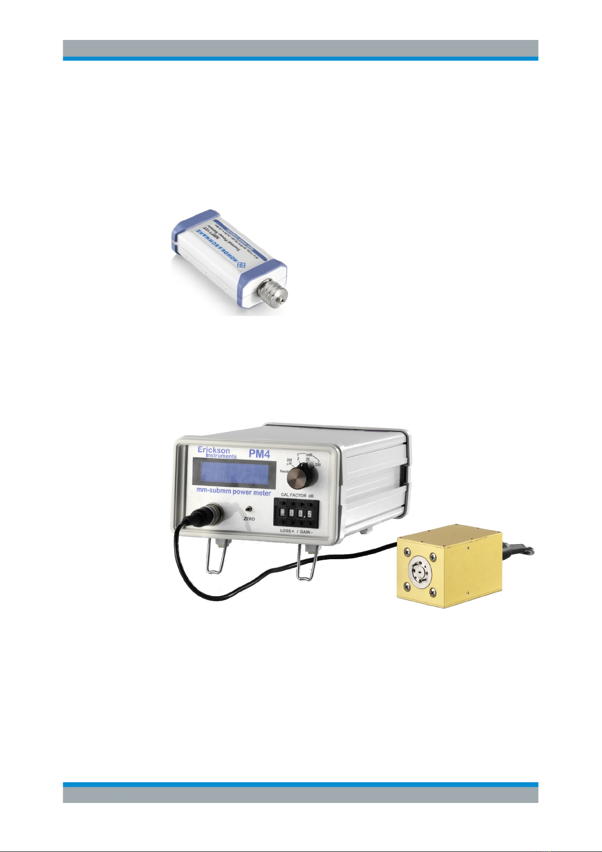
1. Reference receiver calibration
During this step, connect a power meter to the test port of the respective frequency
converter. The calibration consists of a single frequency sweep f1, ..., fn during
which PRF-Out(fj) and PREF(fj) are recorded, where PREF(fj) denotes the power mea-
sured by the VNA reference receiver.
The sweep is performed at the frequency converter's maximum RF level, which is
typically advantageous w.r.t. measurement time and accuracy at the power meter.
For the subsequent steps, the correction factors c(fj) = PRF-Out(fj) - PREF(fj) (on loga-
rithmic scale) are assumed to be independent of the input power level PRF-In.
2. RF input power calibration
This is the actual leveling step, i.e. for each point on the leveling grid, the RF out-
put power PRF-Out(PRF-In, i,fj) is determined.
However, during this step it is sufficient to measure the reference receiver power
PREF(PRF-In, i,fj), which can be performed much faster and with a much higher
dynamic range compared to measuring the RF output power using a power meter.
With the correction factors c(fj) obtained in step 1, the RF output power can then be
calculated as PRF-Out(PRF-In, i,fj) = c(fj) + PREF(PRF-In, i,fj) (on logarithmic scale). The
power meter is no longer required.
3. Waveguide attenuator calibration (E-type frequency converters only)
This is a mandatory step for frequency converters with electronic attenuators (E-
type converter) that are controlled by a R&S ZVA or R&S ZVT via option R&S ZVA-
B8 (see Chapter 3, "Required Equipment", on page 8).
The Leveling Tool records the characteristic of the converter's electronic waveguide
attenuator. The procedure is similar to that of step 2. The power meter is not
required!

Leveling ProcedureSoftware Utility
7Getting Started 1331.3069.02 ─ 03
●Controlling the electronic attenuator of an E-type converter is not supported by the
R&S ZNA, and hence the waveguide attenuator calibration is not available. How-
ever, E-type converters can also be used with their default (unattenuated) output
power.
●To improve the accuracy of PRF-In, it is recommended to perform complementary
power flatness calibrations at the related analyzer ports (including the cables con-
necting the analyzer port to the RF Input of the frequency converter) before starting
the frequency converter leveling.

Required EquipmentSoftware Utility
8Getting Started 1331.3069.02 ─ 03
3 Required Equipment
The Leveling Tool is suitable for test systems consisting of a vector network analyzer
R&S ZNA, R&S ZVA (including R&S ZVA110), orR&S ZVT, in combination with one or
more frequency converters R&S ZCxxx or R&S ZVA-Zxxx(E); see Chapter 3.3, "Fre-
quency Converters ", on page 9
3.1 Vector Network Analyzers R&S ZNA
Up to n converters can be operated with an n-port instrument. However, with n con-
verter ports, the LO signal for the converters must be provided either by the optional
LO Out of the R&S ZNA (R&S ZNA-B8) or by an external signal generator (see refer-
ence [1] in Chapter 10, "Additional Information", on page 33 for details).
Supported firmware versions
The present version of the Leveling Tool requires a R&S ZNA with firmware version
1.90 or higher.
Free firmware updates are available for download on the R&S ZNA product pages
(http://www.rohde-schwarz.com/product/zna). Refer to the instrument's help system or
user manual for installation instructions.
Required Options
●For two-port instruments, which can only have one internal source, the LO signal
for the converters must be provided via R&S ZNA-B8 or an external generator. If
R&S ZNA-B8 is used, then option R&S ZNA-B26 is also required.
●Option R&S ZNA-B26 "Direct IF Access" or R&S ZNAxx-B16, "Direct Generator/
Receiver Access" to connect the Meas and Ref ports of the converters.
●Option R&S ZNA-K8, "Converter Control".
3.2 Vector Network Analyzers R&S ZVA and R&S ZVT
To drive one or more frequency converters, the R&S ZVA or R&S ZVT VNA must have
a maximum frequency ≥ 20 GHz.
The four-port instruments R&S ZVA24/40/50/67 or an R&S ZVT20 with a minimum of
four ports provide the full functionality. It is also possible to operate the frequency con-
verters with R&S ZVA24, R&S ZVA40, or R&S ZVA50 two-port instruments, but this
requires an additional external signal generator (see reference [1] in Chapter 10, "Addi-
tional Information", on page 33 for details).
For R&S ZVA67 and other analyzers equipped with the latest synthesizer board Sy4G,
each test port is driven by its own, independent source. R&S ZVA67 two-port instru-
ments may be operated either with a single frequency converter or with two frequency
Vector Network Analyzers R&S ZVA and R&S ZVT

Required EquipmentSoftware Utility
9Getting Started 1331.3069.02 ─ 03
converters, if an external signal generator is used. On four-port instruments
R&S ZVA67, an external signal generator is necessary to realize setups with 4 con-
verter ports.
The R&S ZVT20 can be operated with up to four frequency converters (depending on
the number of installed ports). With an additional external signal generator, up to 6 fre-
quency converters are supported for frequency leveling.
The R&S ZVA110 enables millimeter-wave measurements from 10 MHz to 110 GHz in
a continuous sweep. Converter ports of other R&S ZVA or R&S ZVT-based test sys-
tems only cover the frequency range of the converter, e.g. 75 GHz to 110 GHz for
R&S ZVA-Z110(E).
Required Options
●Option R&S ZVA<n>-B16, "Direct Generator/Receiver Access" at each analyzer
port
●Option R&S ZVA-K8, "Converter Control"
●Option R&S ZVA-B8 (to establish the power control connection between the ana-
lyzer and the frequency converters with electronic attenuators)
Supported firmware versions
The present version of the Leveling Tool requires a or R&S ZVT firmware version
V3.60 or higher. For the R&S ZVA110 a firmware version 4.11 or higher is required.
Free firmware updates are available for download on the R&S ZVA and R&S ZVT
product pages (http://www.rohde-schwarz.com/product/zva/http://www.rohde-
schwarz.com/product/zvt). Refer to the instrument's help system or operating manual
for installation instructions.
3.3 Frequency Converters
A test system comprises one or more frequency converters R&S ZCxxx or R&S ZVA-
Zxxx(E) plus all the necessary cabling to connect the frequency converters to the ana-
lyzer.
Best leveling results are obtained for frequency converters R&S ZCxxx, R&S ZVA-Z110
Var.03, and R&S ZVA-Z90. For R&S ZVA and R&S ZVT with option R&S ZVA-B8, also
frequency converters with electronic attenuators (R&S ZVA-Z110E and R&S ZVA-
Z90E) provide precise leveling results.
Other frequency converters have limited ability to control the RF output power via the
RF input power and therefore generally do not allow for effective power correction over
wide frequency and power ranges. However the Leveling Tool also performs the cali-
bration steps with these frequency converters.
Frequency Converters

Required EquipmentSoftware Utility
10Getting Started 1331.3069.02 ─ 03
3.4 Power Meter
The frequency range and waveguide interface of the power meter must be in accord-
ance with the used frequency converter.
Recommended Power Meters
●R&S NRP110T or its predecessor R&S NRP-Z58 for frequencies up to 110 GHz
Figure 3-1: R&S
NRP110T
This power meter is equipped with a 1mm coax connector, so a suitable WRxx to
1 mm adapter is required. For details concerning its usage, see the
R&S NRPxxT(N) or R&S NRP-Z Power Sensors User Manual and references no
[3], [4], and [5] in Chapter 10, "Additional Information", on page 33.
●VDI Erickson power meters PM5 or PM4 for frequencies above 110 GHz
The power meter's sensor head is equipped with a WR10 waveguide connector, so
depending on the frequency converter model a suitable WRxx to WR10 waveguide
taper is required. For details concerning its usage, see the respective PMx manual
that is available from the VDI Erickson power meter product pages (http://vadio-
des.com/index.php/en/products/power-meters-erickson).
Power Meter

Required EquipmentSoftware Utility
11Getting Started 1331.3069.02 ─ 03
●Adjust the range switch of the PMx so that the maximum RF output power of the
frequency converter is within the selected power range. See the data sheet of the
related converter type and the suitable PMx manual for details.
●To increase calibration accuracy, zeroing the PMx power meter is recommended
before calibration step 1 (reference receiver calibration). Zeroing is particularly
important if low measurement ranges are required. After mounting the sensor head
to the frequency converter, allow sufficient thermal settling time (1 hour is recom-
mended). After the system has reached thermal equilibrium, switch off the conver-
ter’s RF output power by selecting Channel – [Pwr Bw Avg] > "Power" > "RF Off All
Chanels" on the VNA. Press the [ZERO] button on the front panel of the PMx. After
that, reactivate the converter’s output power by deselecting "RF Off All Chanels".
Other power meters supported by the VNA
In general, the Leveling Tool can work together with any power meter that is supported
by the analyzer firmware. Setup, configuration and operation are similar for all power
meters, however some advanced communication features are limited to R&S NRP
power sensors. For information see "Meas. Delay Time" on page 25.
Power Meter

InstallationSoftware Utility
12Getting Started 1331.3069.02 ─ 03
4 Installation
The Leveling Tool can be installed on any PC running is appropriate for a PC running
Windows XP SP3 or higher. To install it, download the suitable installer (32- or 64-bit)
from the R&S ZNA software page (https://www.rohde-schwarz.com/software/zna/), run
it, and follow the on-screen instructions.
●The Leveling Tool can be installed and run on the R&S ZNA without issues.
●For R&S ZVA and R&S ZVT, it is recommended to install the Leveling Tool on a
separate PC (the "Leveling Tool PC").
●if the Leveling Tool is installed on a PC, R&S ZVA or R&S ZVT running Windows
XP SP3, power meters VDI Erickson PMx are not supported.
In the following we assume that the leveling tool is installed on a separate PC (the
"Leveling Tool PC").

Remote Control ConnectionsSoftware Utility
13Getting Started 1331.3069.02 ─ 03
5 Remote Control Connections
The following sections describe the required remote control connections between Lev-
eling Tool PC, VNA, and power meter. The required connections are the same for all
supported instruments, so we use the R&S ZNA as a typical example.
5.1 Setup with R&S NRP110T or R&S NRP-Z58
These power meters are supported by the analyzer firmware. They can be connected
to any of the USB connectors on the front or rear panel of the analyzer.
The Leveling Tool uses a LAN (or GPIB) connection to operate the analyzer (read/write
settings, query results).
5.2 Setup with a VDI Erickson Power Meter
The VDI Erickson power meters PM5 and PM4 are not natively supported by the ana-
lyzer firmware. The PMx control unit is connected to the Leveling Tool PC via USB.
The PM5 is equipped with a USB interface, for the PM4 an additional USB-to-RS232
adapter is required unless the Leveling Tool PC is equipped with an RS232 interface.
The driver for the PM5 or the USB-to-RS232 adapter has to be installed on the Level-
ing Tool PC before running the tool.
Setup with a VDI Erickson Power Meter

Remote Control ConnectionsSoftware Utility
14Getting Started 1331.3069.02 ─ 03
The Leveling Tool uses a LAN connection operate the VNA (read/write settings, query
results). To add support for the VDI Erickson power meters, the Leveling Tool installs a
suitable power meter driver on the VNA and sets up an external power meter connec-
tion using this driver. The Leveling Tool acts as an adapter between the higher-level
power meter interface specified by the driver file, and the low-level serial interface of
the VDI Erickson power meters.
Remote control of a PMx requires a LAN connection between VNA and the Leveling
Tool PC. USB and GPIB are only supported for VNA remote control.
Setup with a VDI Erickson Power Meter

Preparing Analyzer and ConvertersSoftware Utility
15Getting Started 1331.3069.02 ─ 03
6 Preparing Analyzer and Converters
Before using the Leveling Tool, establish all connections between the frequency con-
verters and the network analyzer. For details, refer to references no. [3] and [4] in
Chapter 10, "Additional Information", on page 33.
6.1 Vector Network Analyzers R&S ZNA
At the analyzer GUI, proceed as follows:
► Open the "Converter Configuration" dialog (System – [Setup] > "Frequency Con-
verter" > "Frequency Converter...") and configure the connected converters and
signal paths as described in the online help of the analyzer firmware; see [2] in
Chapter 10, "Additional Information", on page 33.
Figure 6-1: R&S
ZNA Converter Configuration dialog
For frequency converters of the R&S ZCxxx family, make sure that each converter
(identified by its serial number) is assigned to the correct analyzer port.
Vector Network Analyzers R&S ZNA

Preparing Analyzer and ConvertersSoftware Utility
16Getting Started 1331.3069.02 ─ 03
6.2 Vector Network Analyzers R&S ZVA and R&S ZVT
If R&S ZVA-B8 is installed and you are using converters with electronical attenuators,
don't forget to establish the the power control cable connection.
At the analyzer GUI, proceed as follows:
1. Establish all connections (including the power control cable connection, if applica-
ble) between the frequency converters and the network analyzer. For details refer
to reference no. [3] or [4].
2. If you use a frequency converter of the R&S ZCxxx family that has never been con-
nected to the respective VNA before, connect it to the VNA via USB and follow the
on-screen instructions of the "New Converter Detected" dialog.
3. Ensure that the frequency converter mode of the VNA is active. Open the "System
> System Configuration > Frequency Converter" tab and select the "Type" and
"Use of External Sources" according to your frequency converter type and test
setup. For details refer to reference no. [2] in Chapter 10, "Additional Information",
on page 33.
Vector Network Analyzers R&S ZVA and R&S ZVT

Preparing Analyzer and ConvertersSoftware Utility
17Getting Started 1331.3069.02 ─ 03
Figure 6-2: System Configuration > Frequency Converter tab
For frequency converters of the R&S ZCxxx family make sure the converters are
individually assigned to their respective ports:
Vector Network Analyzers R&S ZVA and R&S ZVT

Program Start and VNA Remote ControlSoftware Utility
18Getting Started 1331.3069.02 ─ 03
7 Program Start and VNA Remote Control
Before starting the Leveling Tool, ensure that you have carried out all the preparative
steps described in Chapter 6, "Preparing Analyzer and Converters", on page 15.
Whenever you start the Leveling Tool, you are requested to establish a remote control
connection to the analyzer.
1. On the Leveling Tool PC, select "Leveling Tool" from the Windows Start menu.
You are prompted with the "Select Connection Configuration" dialog:
Figure 7-1: VNA connection configuration
2. In the "Select Connection Configuration" dialog, select/specify the appropriate con-
nection properties for your analyzer.
E.g., select connection type "TCP/IP", "HiSLIP" (R&S ZNA only), or "VXI-11" and
enter the "IP Address" of the VNA. If the Leveling Tool is installed directly on the
VNA, select "Local" and enter "IP Address" 127.0.0.1 (default).
The "VISA Connection String" is automatically composed from the GPIB/LAN set-
tings, but can also be entered manually.
3. Select "Test Connection" to test the communication between Leveling Tool and
analyzer.
If the connection was successfully established and the VNA is prepared for fre-
quency converter operation, the connection test is successful:

Program Start and VNA Remote ControlSoftware Utility
19Getting Started 1331.3069.02 ─ 03
Otherwise a warning message is displayed, e.g.
Select "OK" to return to the "Select Connection Configuration" dialog.
4. In the "Select Connection Configuration" dialog, click "OK" to establish the connec-
tion or "Cancel" to abort the connection attempt.
You can start another connection attempt by selecting "Configuration" from the
main window of the Leveling Tool (see "Configuration" on page 24).
On subsequent program starts, the configuration of the last successful connection is
reused.

External Power Meters: Control ConnectionSoftware Utility
20Getting Started 1331.3069.02 ─ 03
8 External Power Meters: Control Connection
Before the leveling can be performed, the power meter has to be configured in the ana-
lyzer firmware and the control connection between analyzer and power meter must be
established.
8.1 R&S NRP110T or R&S NRP-Z58
To establish a remote control connection between the VNA and an R&S NRP110T or
R&S NRP-Z58, the power meter has to be connected to the analyzer via USB (see
Chapter 5.1, "Setup with R&S NRP110T or R&S NRP-Z58", on page 13). If "Auto Con-
fig R&S NRP Power Sensors" is enabled, the power meter is automatically configured
by the analyzer firmware, otherwise it has to be configured manually. See reference [2]
for background information.
Figure 8-1: Auto config for R&S
NRP-Z58 (R&S
ZNA)
R&S NRP110T or R&S NRP-Z58
Table of contents
Other Rohde & Schwarz Media Converter manuals

Rohde & Schwarz
Rohde & Schwarz SGU100A User manual

Rohde & Schwarz
Rohde & Schwarz ZVA-Z90E User manual

Rohde & Schwarz
Rohde & Schwarz TSME30DC User manual

Rohde & Schwarz
Rohde & Schwarz ZVA-Z75 User manual

Rohde & Schwarz
Rohde & Schwarz RT-ZF6 User manual

Rohde & Schwarz
Rohde & Schwarz GC 003 User manual