ROLA-CHEM 554200 User manual

MODEL 554200
pH Digital Controller
MODE
FLOW SWITCH pH OUTPUT
FEED
TIME
SET
LEVEL
pH
pH
CALIB
POWER
ALERT
FEED pH
AUTO
FLOW
Operating Manual
Rola-Chem Digital Controller PN 554212 11/22/06 Page: 1 of 16

Rola-Chem Digital Controller PN 554212 11/22/06 Page: 2 of 16
QUICK START REFERENCE
Use this section for reference - please read all safety instructions and
appropriate manual sections for installation and operation instructions.
On/Off:
-press the mode button to turn the unit on.
note: ‘FLOW’ light must illuminate.
-press and hold the mode button to turn the unit off.
“OFF” will be displayed in the windows
To Operate:
-press and release the mode button until the “AUTO” light is lit.
Unit will now operate in the factory preset settings:
- Set level: pH = 7.4
- Feed times: 0.6 second feed with a 5 minute delay
- Limits/Alerts: pH; 8.0 hi, 7.0 low
To Change Settings:
- Press and release the mode button –AUTO light off.
Note: Once the settings are changed, they will remain at
those settings until they are changed again.
- Set Level: press the Set Level button until the desired set point
is reached.
- Feed Time: press the Feed Time button until the desired feed
time is reached.
The number represent the seconds of feed time
(all with 5 minute delays).
Range is 0.6 to 900 sec. (15 min.).
Constant feed is ‘con’.
Other: See the appropriate manual sections for:
-calibrating the pH sensor
-changing function (acid/base feed)

Rola-Chem Digital Controller PN 554212 11/22/06 Page: 3 of 16
Table of Contents
Section title Page
--- Quick Start Reference Inside Cover
1.0 Safety Instructions 4
2.0 Description and Specifications
2.1 General Description 5
2.2 Specifications 6
2.3 Description of controls 7
3.0 Installation
3.1 Locating the controller 8
3.2 Mechanical installation 8
3.3 Power access panel 8
3.3.1 Fuses 9
3.3.2 Flow Switch 9
3.3.3 Acid/Base Feed 9
4.0 Operation
4.1 Startup 9
4.2 PH settings 10
4.3 Operating mode 10
4.4 Reset 11
5.0 Troubleshooting 12
6.0 Warranty 13
7.0 Appendix
7.1 Water Chemistry Ranges-NSPI 14
7.2 Typical system installations 14

Rola-Chem Digital Controller PN 554212 11/22/06 Page: 4 of 16
1.0 Safety Instruction
A- WARNING: Do not shut down circulating and control
system immediately after using pool, spa or hot tube.
Systems must operate until water chemistry is stable. Systems must be
restarted before water chemistry is out of NSPI recommended ranges or
water chemistry must be manually corrected.
B- WARNING: Removing power from circulating pump must
also remove power from the controller.
Provide a properly located outlet controlled by the circulating pump
circuit.
C- WARNING: Pool water must be balanced and stabilized
before operating this controller.
(See ‘READ ME FIRST’ document for further information.
D- WARNING: Use a devise such as a flow switch to shut-off
power from the controller in the event of pool pump or
circulation failure.
It is not safe to automatically dispensed chemicals into a circulating
system that is not running.
E- WARNING: Controller uses microprocessor.
Wireless communication equipment or other electrical operated devised
operated in close proximity may cause inadvertent actuation of chemical
feed pumps.
F- WARNING: Risk of electric shock.
Connect power cord to ground-fault circuit interrupter (GFCI). Contact
qualified electrician if you can not verify that your installation meets
local electrical codes, including grounding of water system components.
G- WARNING: Do not bury cords.
Locate cord to minimize abuse from lawn mowers, trimmers and other
equipment. Replace damaged cords immediately. Do not use extension
cords.
H- WARNING: Do not install within an outer enclose or
beneath skirt of tub or spa unless so marked.

Rola-Chem Digital Controller PN 554212 11/22/06 Page: 5 of 16
2.0 Description and Specifications
2.1 General Description
The controller is a microprocessor-based chemical automation system,
which continuously monitors and maintains the pH balance in a
swimming pool or spa.
The pH is displayed using sun-bright light emitting diodes. The pH
levels is continuously monitored and displayed on the controller’s front
panel. The pH controller has been designed to be user friendly. One
MODE button and three SET buttons allow the operator to easily set
parameters.
The pH display range is 6.8 to 8.2 with a .1 unit resolution. The pH set
point is adjustable from 7.0 to 8.0 in .1 pH steps, with a factory default
set point of 7.4 pH. During a feed cycle, the feed lamp will blink when
chemicals are being feed and illuminate continuously during the feed
delay portion of the feed cycle. The Alert lamp will flash when the pH
reading is higher or lower than the factory set limits for more than 10
minutes and prevent the feeding of pH chemicals.
The feed cycle is a timed based ‘feed then delay’ system. The
controller has a series of fixed feed times (0.6 to 900 sec.) with
associated delays as well as a constant feed mode (con). A feed cycle
consists of a feed time plus a delay time. Example, a 30 second feed
time followed by a five-minute delay would have a 5½ minute feed
cycle. The chemical feeder dispenses chemical only during the feed
time portion of the cycle and then waits for a delay period to allow for
chemical to dispense throughout the swimming pool or spa.
Overfeed alert occurs after 120 minutes ‘continuous’ feed and 30
cycles in timed feed mode. Feeders will be disabled and display will
flash (requiring reset).
The controller incorporates an internal non-volatile memory in which
all factory default settings as well as field-modified settings are stored.
The internal memory is not affected by power interruption and requires
no backup battery.
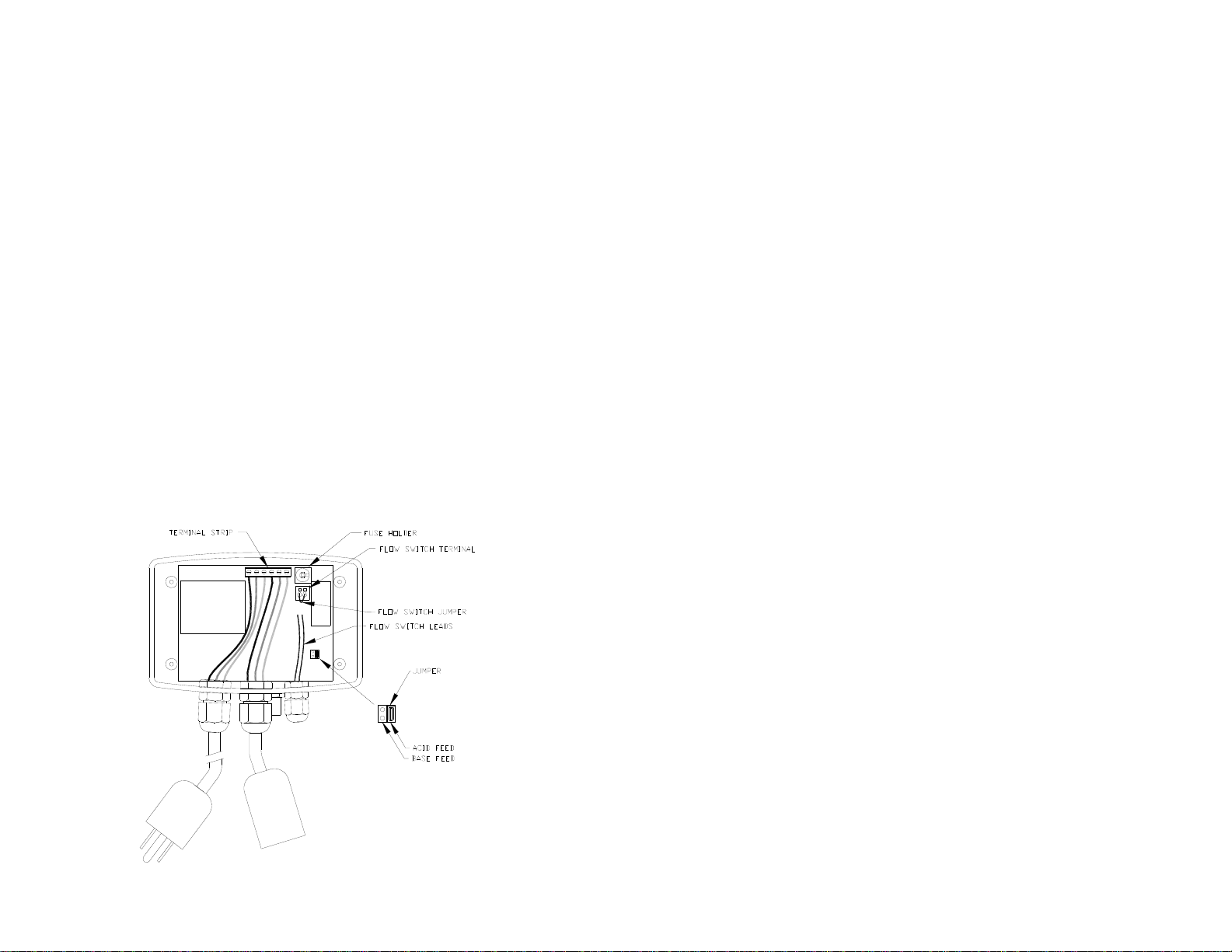
The pH output is capable of handling 5 amps at 120 Volt AC. The
relay output is fused and transient protected. An internal terminal strip
is provided for field wiring of the controller. The internal step-down
transformer has a class-two energy limiting rating to provide for
electrical safety.

Rola-Chem Digital Controller PN 554212 11/22/06 Page: 6 of 16
NOTE: When automating any body of water, it is essential to size the
feeders to reach desired levels in a relatively short period of time.
Generally, automating an existing body of water with existing feeders
will require the output of the feeders be increased accordingly. If
feeders are unable to keep up with demand in a short period of time,
automation becomes ineffective.
2.2 Specifications
Display: pH 6.8 to 8.2
Control: pH 7.0 to 8.0
Factory default: pH 7.4
Input Power
120 Volts AC, 50/60 HZ, 3 wire grounded power cord.
GFCI source required
Output Power
120 Volts AC, 50/60 HZ, --5 amps (fused)
Two 3-wire grounded power receptacles
Terminal strip for hardwire applications.
Displays:
pH reading – red digital LED
Flow/Power indicator -green LED
Auto (operating mode) indicator -red LED
Alert indicator -red LED
Feed indicator -green LED
(NOTE- lamps flash during the feed time and are on constant
during the delay time of the feed cycle.)
Operating Temperature: 40 to 120° F
Features and Options
+ pH setting + pH feed/delay time + alert (high & low)
+ Acid/base feed + calibration + Flow switch input
+ Feed time out + fused outputs

Rola-Chem Digital Controller PN 554212 11/22/06 Page: 7 of 16
2.3 Description of Controls
Modes: The controller has two modes of operation:
•ON/OFF/Set mode
•AUTO mode- operating
To move from one mode to another simply press the MODE button.
On/off /Set mode:
•To turn the controller “on”, press the MODE button.
•To turn the controller “OFF” press and hold the MODE button
for two seconds until the pH displays read “OFF”.
Release the MODE button and the controller turns off and the
display goes blank.
Note: Turning the controller “OFF” using the MODE button
simply turns off the controller functions, but does not turn off the
power to the controller. The FLOW lamp is both the power light
and a flow indicator when an optional flow switch is used.
•When Flow light is on and Auto light is off, levels can be set.
Set level button: Pressing the set level button once will display the
current set level. To change the set level, press the set level
button (which displays in 0.1 pH increments) until the desired
level is reached.
Feed time: The feed times are displayed in seconds.
Each feed cycle includes a five (5) minute delay time.
Pressing the feed time button allows the user to select
available feed times. Release the button when the desired pH
feed time is reached. To set the controller in constant feed,
release the button when the display reads “con”.
pH calibrate: This button allows calibration of the pH sensor to a
buffer or sample tested with a test kit. Press the pH CALB
button to set the pH reading to the desired pH level.
AUTO mode: This is normal operation mode. The controller operates
the feeder to automatically maintain the parameters set for pH.

3.0 Installation
3.1 Locating the controller
Install the chemical pump/ feed systems as shown in manuals
included with the feeders. Before installing the controller, it is
important to do a site assessment to consider where and how
you will mount the unit. The controller should be mounted on a
wall or other surface within eight feet of the feeder, at least ten
feet away from the edge of the water, and within six feet of the
GFCI power source. Never mount a controller above or near an
acid tank. See appendix for typical feed system schematics.
3.2 Mechanical Installation
Once the site is selected, obtain screws or anchors to securely
mount the controller on the wall or a panel.
Screw slots are provided in the controller enclosure. Access to
flow switch wires, acid/base changes and terminals is located on
the back of the enclosure.
3.3 Power access panel
Access to terminals is through the back of the enclosure. With
the controller removed from wall/panel, remove four screws
holding enclosure panel to enclosure body.
Rola-Chem Digital Controller PN 554212 11/22/06 Page: 8 of 16

Rola-Chem Digital Controller PN 554212 11/22/06 Page: 9 of 16
3.3.1 Fuses
Fuses protect the controller from defective feeders. They are located
inside the enclosure. The fuse holders are shipped with 5 Amp fuses.
3.3.2 Flow Switch Terminal
The controller has a flow switch terminal shipped with a ‘jumper’ in
place. The terminal must either have the jumper or a flow switch
installed. The flow light on the face of the controller is also indicates
the controller is connected to a live power source. If the terminal does
not have a closed circuit, the controller will not turn on.
To install a flow switch, remove the jumper and attach flow switch
leads. The jumper should be retained to assist in trouble shooting.
NOTE: It is recommended that an inline filter be used to help keep
the flow manifold (including probes) and flow switch free from
debris (see Manifold Operating Manual). Debris may obstruct flow
switch and prevent the switch from functioning.
3.3.3 Acid/Base Feed Selection:
The controller has a terminal shipped with a ‘jumper’ used to select
acid or base chemical. The jumper can be moved to change type of
feed. Factory setting is acid feed. Acid feed mode will feed chemical
when the pH reading is above the pH set point.
4.0 Operation
4.1 Startup
Do not add chemicals to the feeders until all start-up operations are
completed. Using a DPD test kit, manually adjust and balance the pool
to acceptable ranges. Automation should be used to maintain chemical
levels, not to balance a pool that is out of acceptable ranges. With the
controller in the OFF Mode, turn the filter pump on and check for leaks
in the system and flow through the flow cell. The flow lamp will be
illuminated if the controller has power, it is connected to the flow
switch and there is adequate flow. If a flow switch is not attached, the
flow lamp will be illuminated if there is a jumper in the flow cell
terminal. It is recommended that a flow switch always be used.

Rola-Chem Digital Controller PN 554212 11/22/06 Page: 10 of 16
4.2 pH setting
Press and release the controller MODE button until the AUTO light is
off. Then select the desired set level and feed time cycle.
4.3 pH Calibration
Always calibrate using water from the sample port of the flow cell,
unless using preset buffer solution. It may take up to 24 hours before
the sensors acclimate to the system so recalibrate 24 hours after the
first calibration. The pH sensor can drift slightly over time and
calibration will offset this drift. The pH sensor should be calibrated
every four to six weeks.
4.4 Operating mode
Press the MODE button until “AUTO” is lighted. This is the
operational mode for the controller. The controller must be in this
mode to maintain the desired parameters.
Timed feed settings: The feed lamp will flash during the feed time and
be constant during the delay time of the feed cycle. Power will be
supplied to feeder until set-point is reached and feed cycle is
completed. If over feeding is occurring, consider shorter feed cycle.
Constant feed setting: The feed lamp will flash while feeding. Power
will be supplied to feeder until set-point is reached.
The feed lamp will not activate when the pH alert lamp is on (pH is
below or above the alert settings).
Low feed rates can cause the feeder to lag or feeding to be extended. A
high feed rate can result in too much pH chemical being added.
To verify the feed type (acid or base) adjust pH “set” level above the
pH indicated on display. The feed lamp should come on if the
controller is in acid feed mode. If the controller is in base feed, the feed
lamp will come on if the pH indicated is below the pH “set” level.

Rola-Chem Digital Controller PN 554212 11/22/06 Page: 11 of 16
4.5 Reset
The controller can be reset at any time to the default factory settings.
Follow the steps below:
A. Turn the controller ‘off’ by holding down the mode button
B. Simultaneously depress and hold the ‘Set Level’ and ‘pH
Calib’ buttons
C. Turn the controller ‘on’ by pushing the mode button
D. The display will read ‘LD’
E. Release the ‘Set Level’ and ‘pH Calib’ buttons
F. Turn the controller ‘off’ and then ‘on’.
Note: This last step is extremely important since this puts
the controller back in the operating mode. If step F is not
performed, the controller is in the test mode and it will not
operate correctly.

Rola-Chem Digital Controller PN 554212 11/22/06 Page: 12 of 16
5.0 Troubleshooting-
5.1 Chemicals not feeding
* FLOW light on Controller must be illuminated. Check flow switch
(manifold) if light is not on (Section 3.3.3)
*Feeder power and time switches must be in ‘ON’ position. Check
feeder by using alternate power source.
*Factory setting for feed time is 0.6 sec on with 5 minute delay.
Feeders may require longer feed time.
5.2 Displayed chemical level don’t correspond to actual
* Sensors (probe) is attached connector.
* Sensors (probe) need cleaning.
* Sensors (probe) need replacing.
5.3 Set-points not being reached or maintained
*Factory setting for feed time is 0.6 sec on with 5 minute delay.
Feeders may require longer feed time. If time is too short, set-points
will not be maintained. If time is too long, overfeeding chemicals
will occur. Correct time is dependent of multiple factors such as
pool/spa water volume, feeder output, chemical concentration and
chemical needs.
* Controllers are designed to maintain set-points. Do not expect
Controllers to make major adjustments—major changes should be
done manually.
* Pump/feeders must be large enough to reach desired set-points in a
relatively short time. Automation using controllers may require
larger feeder or more concentrated chemicals than system that uses
continuous time controlled feeding (i.e. feeders only).

Rola-Chem Digital Controller PN 554212 11/22/06 Page: 13 of 16
6.0 Warranty and Service-
6.1 Limited Warrenty
Rola-Chem Corporation warrants the original purchaser that this unit is
free from manufacturing defects in material and workmanship from the
date of the original purchase for one (1) year.
If this unit fails within the one (1) year period, it will be repaired or
replaced (Rola-Chem’s option) at no charge, when returned to Rola-
Chem Corporation with proof of purchase receipt. This warranty does
not apply to any product damage caused by improper use, accident,
misuse, improper line voltage, fire, flood, lightening, earthquake or
other acts of nature, or, if product was altered or opened by anyone
other than qualified Rola-Chem personnel.
All expendable items- hoses, etc., are not covered under this warranty.
Heavy duty probes are warranted from the date of original purchase for
one (1) year.
Rola-Chem Corporation, under no circumstances, shall be liable for any
consequential damages directly or indirectly caused by this unit. Please
observe all rules and regulations required by state and local regulations,
building codes, health codes, OSHA, etc.
6.2 Service Procedure
For operation assistance in the United State, please call:
(800) 549-4473 or FAX (651)-653-0989
Monday thru Friday 8:00 am-5:00 pm, Central Time.
Rola-Chem Corporation has specialized knowledge and equipment to
properly test your unit and help you with special problems. After talking
to our service personnel, the product in need of service should be
shipped with RGA#, freight prepaid, via UPS if at all possible to:
Rola-Chem Corporation
5858 Centerville Road
St. Paul, MN 55127-6804

7.0 Appendix
7.1 WATER CHEMISTRY RANGES
(These ranges are in accordance with suggested NSPI
Standards for swimming pools.)
pH: 7.4 -7.6
Alkalinity: Approx. 80-120 ppm ** (parts per million)
Higher levels may be acceptable in areas where it naturally
occurs in the local water supply.
Consult a pool professional in your area.
Cyanuric Acid: 0-50 ppm.
(Maintain at 30 ppm or less for best probe life.)*
TDS (Total Dissolved Solids): 300 - 2000 ppm
Calcium Hardness: 200-400 ppm
Free Chlorine: 1.0 - 3.0 ppm (> 700 millivolts ORP)
*20-30 ppm of cyanuric acid provides approx. 95% of the shielding
effect for chlorine.
**When using tri-chlor, recommended alkalinity is 95-125 ppm.
7.2 Typical System Installations
FILTER
**SAFETY FLOWSWITCH TO ENSURE
CIRCULATION TO CONTROL PROBES
AND INDICATOR THAT POOL
CIRCULATION IS OCCURRING.
*SAFETY FLOWSWITCH FOR
PROTECTION OF HEATER AND
TO ENSURE DILUTION OF
CHEMICAL INTO POOL.
*** OPTIONAL FILTER TO
HELP KEEP MANIFOLD
AND PROBES CLEAR OF
DEBRIS.
SYSTEM USING ELECTROLYTIC CHLORINE GENERATOR
EARTH
GROUND
pH CONTROL WITH ACID PUMP
POOL
PUMP
WATER
FROM
POOL EARTH
GROUND
*FLOWSWITCH WATER
TO
POOL
CELL
pH
CONTROLLER
PUMP
***FILTER
HEATER
**FLOWSWITCH
ELECTRICAL
OUTLET
CONTROLLED BY
CIRCULATION
SYSTEM MANIFOLD
CHLORINE
GENERATOR
CONTROLS
ACID
Rola-Chem Digital Controller PN 554212 11/22/06 Page: 14 of 16

Rola-Chem Digital Controller PN 554212 11/22/06 Page: 15 of 16
-- NOTES --

Rola-Chem Digital Controller PN 554212 11/22/06 Page: 16 of 16
-- NOTES --
Table of contents
Other ROLA-CHEM Controllers manuals
Popular Controllers manuals by other brands

LSI
LSI MegaRAID SCSI 320-0 Zero-Channel RAID Controller Series... Configuration

Aaeon
Aaeon AEC-VS01 manual

Wiznet
Wiznet W5300 Porting guide

THORLABS
THORLABS BPC301 user guide

KMC Controls
KMC Controls SimplyVAV BAC-8001 Application and installation guide

Trinamic
Trinamic PANdrive PD42-1-1370 Hardware manual