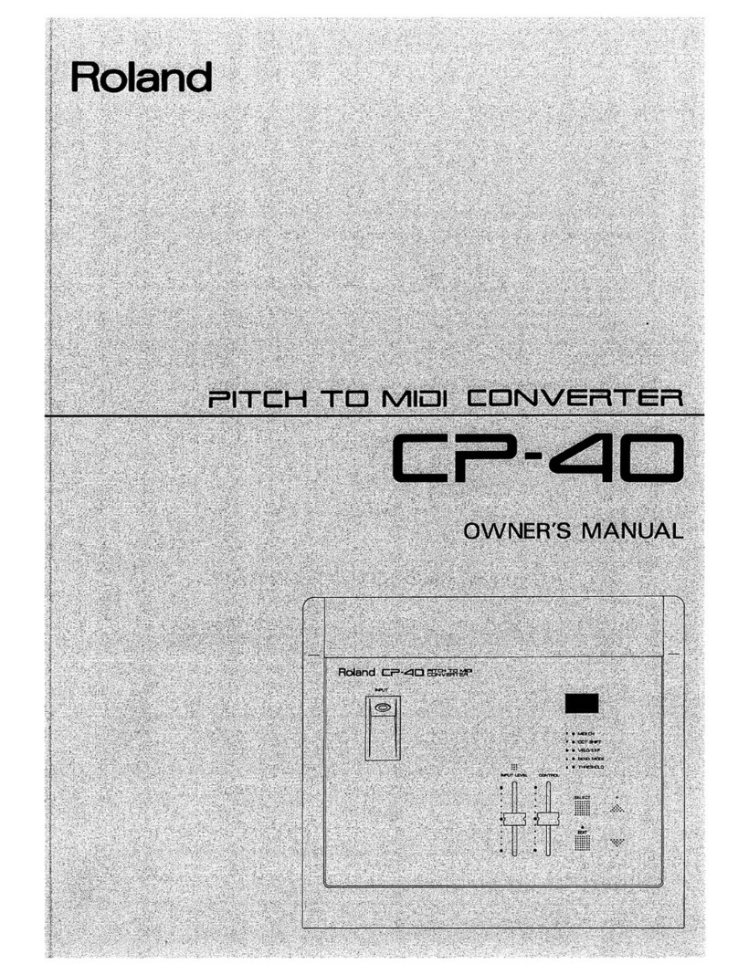
Roland CP-40 User manual

‘
ne
eae
a
ssa
i
Hedi:
ae
a
:
mie
Se
ee
ca
i
ret
re
it
a
i
Spe
ae
my
ee
a
i
ao
aint
Route
oo.
i
ae
Sanh
BOE
a
:
73
oa
ih
.
es


Thank
you,
and
congratulations
on
your
choice
of
the
CP-40
Pitch-to-MIDI
Converter.
To
take
full
advantage
of
the
superb
features
offered
by
the
CP-40,
and
to
ensure
satisfaction
for
years
to
come,
please
read
this
Owner’s
Manual
in
its
entirety
before
starting
out.
BM
CONTENTS
HE
FEATURES
OF
THE
CR-40
.0----.cicccecceec
eee
tc
cere
cence
nen
e
cence
eee
ene
eee
EEE
EE
EAE
E
EE
EES
EARL
SESE
EEE
SEEGER
EGE
EAG
ES
9
HE
IMPORTANT
NOTES
«---0-0-0----
2c
ee
ccec
ee
cec
reece
cee
e
rece
e
eee
n
eee
n
ene
REO
REESE
EEE
EE
REE
SEE
EE
EEE
EA
EAE
EO
EEE
EGER
EEE
EEE
E
EEE
3
4.
PANEL
DESCRIPTIONS
«-----:----cceccceececee
rece
ener
et
eee
ee
ee
nen
eee
ee
nena
eee
aed
eens
nen
eA
DEE
ee
EE EE
RHEE
RHEE
ESSE
EEE
EA
EH
EEE
EES
6
(1)
Front
Panel]
crercrscccccc
rece
ccs
e
ses
eee
cence
ence
neeeeerecer
ener
eeeee
eens
ence
eee
ea
seen
eee
e
rs
ee
ene
ease
a
eee
nate
eRe
SEE
ETE
ee
ee
eS
6
(2)
Rear
Pane]
crccceccscccccccecreccercccsectcscessrecenesearcaeeee
reece
ners
neers
eee
e
ne
eee
esse
nesses
sense
tenes
en
eEN
eee
EEE
LER
EE
ES
7
2:
GETTING
STARTED
550.
focokees
dee
wees
seston
e
hese
ig
cased
deine
sedee
ee
ede
See
eeeenesten
eden
vote
ons
AUSamabagdocss
es
bdadds
queer
g
(1)
MIDI
Data
Transmitted
by
the
CP-d
se
reeeececceceeceenne
nee
veceereweeeeeeeereee
eee
ee
rene
eee
eee
eee
heen
ner
en
seen
nentes
8
(2)
Making
Connections
a.eiv's
bisa
le
bie
ore
Fels
'¥
ane'6'y
OLnie(S
OD
we
aie
wa
Ba
OC
d
OTMS;6
Wgibie
bg.)
'sle lain
a
a
whe
G.S
ein.
e.a¥b
918
vain
SL
SO.¥,0
ww
dbase
DUSiNaibOee
mama
ewaaecewe
9
(3)
Powering
Up
rere
ere
rerree
er er
reer
ree
ere
rrer
ee
reer
eres
reer
eer
ee
rer
ee
ee
er
eT
Tree
errs
ee
Tereerere
rere
cece
rere
eee
Teer
reer
eye
eee
ll
5.
THE
TWO
MODES
255
io
i
esc
decaeee
esac
aside
cs
sad
ceca
ded cab
eave
eeges
devebeseedcseasausseeges
eoitededeasedloueaedse
12
(1)
Normal
Mode
rere
Reet
rer
reer
e
rer
ee
rerr
Terre
rt
rere
rer
rere
errr
reer
rere
rere
reer
rere
eres
rer
Teer
er
sere
eee
eT
ee
eer
ere
Trey
yes
12
(2)
Edit
I\Y,
Wole
(swe
ee
tree
ete
eee
ee
eee
errr
ss
13
4.
ADJUSTING
INPUT
LEVEL
------
0:
ccc
cc
eer
c
eee
r
eter
ene
e
ern
r
eee
e
eet
neenn
ener
een
e
en
ee
eens
eee
eee
e
eee
nee
bene
SEN RES
EaeY
14
5.
CONFIGURING
MIDI
DATA
----:-
ccc
reece
reer
e
ee
terete
entre
eee
ener
renee
nnn
e
eee
ere
e
eee
Ee
Eee
REE
EEE
EE
OEP
ORE
E
OEE
E
HEHE
16
(1)
MIDI
Channel]
crcrereccccrrereccer
tte
cerectee
teen
enneeerecceeceeeeeetareacer
cect
creas
eee
er
eneen
eens
nes
eneneenee
tenet
ebean
estes
17
(2)
Octave
Shift
-ccccccccsecc
cece
eee
eeer
ects
seer
eeeee
rect
e
nee
n
reece
nee
tect
ee
tenets
eneeerenenenranetenereseeseraenseentsseaees
17
(3)
Velocity/Expression
ere
eee
eee
ee
eee
eee
ee
eee
eee
eer
ee
ere
reer
rre
rece
errr
eee
reer
ee
creer
eer
r
ere
eee
ee
ee
ere
reer
rere
Trey)
17
(4)
Bend
Mode
eter
ee
Tere
rere
reer
tere
rere
Terre
rere
Tere
e
Terr
rece
rr
ee
er
eee
eee
er
ee
eee
eee
ee
eee
ee
eee
eee
ere
ee
ee
eee
Te
eee
ey
18
(5)
Threshold
rer
er
ere
errr
eee
reer
re
rere
eer
Tee
eer
ee re
reer
r
rere reer
ere
eT
eT
Serer
eee
eee
ee
re
eee
ere
re
ee
er
eer
eee
ers
18
6B.
EXAMPLE
SETUPS
«>
---.---
ccc
ee
eect
r
cece
cece
rece
ner
e
ener
n
entree
eter
ee
MEME
REET
ORR
EEE
E
ESE
O
ESTEE
EERE
E
REE
E
RO
ER
EOE
ED
ESE EEE
19
(1)
Use
with
a
Desktop
Music
System
ere
r
errr
rer
ee
rarer
ere
rere
rere
errr
er
er
ere
reer
rr
ere
Tee
errr
eee
er
errr
errr
reer
ee
ee
19
(2)
Use
with
a
MIDI
Sequencer
rei
aisl
pp
ersielnreinlSyayere’
we
a
lb'
sla oie
a-a'e
-slavels
s
aie,8
Se
clave’
Rusia
bruja
lave
a:b
-ajeia
Wiss
RieialaiSiaws
Dials
era's
a,oaieyee
edie
Ajerwie
sinuea
clei
e's
20
7.
COMMON
PROBLEMS
AND
SOLUTIONS
-----.-::.0:2ccccccc
cee
ceeere
nsec
neces
renee
eens
ee
nb
eens
rape
ne
eH
ELE
Desa
eH
eae
HOES
21
HE
MIDI
IMPLEMENTATION
«-------
eee
cece
reece
reer
eee
e
reece
cece
eee
n
eee
e
eee
n
ete
nee
en
ene
e
tenets
eee
e
eee
EE
eee
ee
DERE
NED
Ee
eee
EEE
EE
ES
2?
BE
SPECIFICATIONS
---0-
ees
eee
e
cece
eee
e
eee
cece
eee
cence
nner
c
ee
eee
e
eer
a
bene
t
ance
ren
n
eee
eens
terete
nee
nen
erect
ee
eeeerneenes
94
Copyright
©
1990
by
ROLAND
CORPORATION
All
rights
reserved.
No
part
of
this
publication
may
be
reproduced
in
any
form
without
the
permission
of
ROLAND
CORPORATION.

Features
of
the
CP-40
@
The
CP-40
converts
audio
signals
from
microphone
or
line-level
input
sources
into
MIDI
signals
in
real
time
Audio
information,
whether
from
someone
singing
or
playing
an
electric
guitar,
is
instantaneously
converted
into
MIDI
signals.
This
conveniently
allows
you
to
gain
control
over
other
MIDI
devices
—
without
requiring
a
MIDI
equipped
keyboard,
or
guitar
controller.
@
Volume
and
Pitch
Changes
are
also
Controllable
The
volume
level
of
input
audio
signals
can
be
output
as
either
Velocity
or
Expression
messages.
Moreover,
since
even
small
shifts
in
pitch
(those
less
than
a
semi-tone)
can
be
transmitted
as
Pitch
Bend
messages,
every
nuance
of
your
music
is
captured.
@
Convenient
for
input
into
a
Desktop
Music
System
The
MIDI
data
generated
by
the
CP-40
can
be
used
as
an
input
source
for
real-time
recording
in
Desktop
Music
Systems
(such
as
Roland’s
“TENTRAX”)
or
MIDI
sequencers
(such
as
the
MC-500mk
II).

B
IMPORTANT
NOTES
When
using
an
AC
adaptor,
be
sure
that
it
is
one
supplied
by
the
manufacturer.
Use
of
any
other
power
adaptor
could
result
in
damage,
malfunction,
or
electric
shock.
[Power
Supply]
@
When
making
any
connections
with
other
devices,
always
turn
off
the
power
to
all
equipment
first;
this
will
help
prevent
damage
or
malfunction.
@
Do
not
use
this
unit
on
the
same
power
circuit
with
any
device
that
will
generate
line
noise,
such
as
a
motor
or
variable
lighting
system.
@
The
power
supply
required
for
this
unit
is
shown
on
its
nameplate.
Ensure
that
the
line
voltage
of
your
installation
meets
this
requirement.
@
Avoid
damaging
the
power
cord;
do
not
step
on
it,
place
heavy
objects
on
it
etc.
@
When
disconnecting
the
AC
adaptor
from
the
outlet,
grasp
the
plug
itself;
never
pull
on
the
cord.
@
If
the
unit
is
to
remain
unused
for
a
long
period
of
time,
unplug
the
power
cord.
[Placement]
@
Do
not
subject
the
unit
to
temperature
extremes
(eg.
direct
sunlight
in
an
enclosed
vehicle).
Avoid
using
or
string
the
unit
in
dusty
or
humid
areas
or
areas
that
are
subject
to
high
vibration
levels.
@
Using
the
unit
near
power
amplifiers
(or
other
equipment
containing
large
transformers)
may
induce
hum.
@
This
unit
may
interfere
with
radio
and
television
reception.
Do
not
use
this
unit
in
the
vicinity
of
such
receivers.
@
Do
not
expose
this
unit
to
temperature
extremes
(eg.
direct
sunlight
in
an
enclosed
vehicle
can
deform
or
discolor
the
unit)
or
install
it
near
devices
that
radiate
heat.
[Maintenance
|
@
For
everyday
cleaning
wipe
the
unit
with
a
soft,
dry
cloth
(or
one
that
has
been
slightly
dampened
with
water).
To
remove
stubborn
dirt,
use
a
mild
neutral
detergent.
Afterwards,
be
sure
to
wipe
the
unit
thoroughly
with
a
soft,
dry
cloth.
@
Never
use
benzene,
alcohol
or
solvents
of
any
kind,
to
avoid
the
risk
of
discoloration
and/or
deformation.

ARAL
RAA
PAL
{
Additional
Precautions
|
@
Protect
the
unit
from
strong
impact.
@
Do
not
allow
objects
or
liquids
of
any
kind
to
penetrate
the
unit.
In
the
event
of
such
an
occurrence,
discontinue
use
immediately.
Contact
qualified
service
personnel
as
soon
as
possible.
@
Should
a
malfunction
occur
(or
if
you
suspect
there
is
a
problem)
discontinue
use
immediately.
Contact
qualified
service
personnel
as
soon
as
possible.
[About
the
Supplied
Microphone
|
@
Before
using
the
supplied
microphone
you
need
to
install
a
battery.
(Dry
battery:R03(AAA)type)
@
The
microphone
is
provided
with
its
own
power
switch
(turns
current
from
battery
on
and
off).
Always
make
sure
to
slide
it
to
the
“OFF”
position
when
the
microphone
is
not
being
used.
Roland
ON
Power
ON
OFF
Power
OFF
@
On
average,
the
battery
should
last
for
about
5,000
hours.
However,
anytime
you
notice
that
the
microphone
has
decreased
in
sensitivity,
or
that
the
sounds
picked
up
are
not
converted
to
MIDI
correctly,
replace
the
battery
with
a
new
one.
@
If
you
do
not
intend
to
use
the
microphone
for
an
extended
period
of
time,
remove
the
battery
as
a
precaution
against
leakage
and
possible
damage.

@How
to
Replace
the
Battery}
@)
Remove
off
the
windscreen
covering
the
tip
of
the
microphone.
Zé:
al
Wind
screen
(ese
BP
@
Screw
off
the
microphone’s
cap
by
turning
it
counterclockwise.
B
@
Remove
the
battery,
and
while
carefully
observing
the
polarity
(“}”
versus
“—"},
replace
it
with
a
new
one.
@
O
Dry
Battery
@
Once
the
new
battery
is
in
place,
reverse
steps
(7)
and
(2)
to
screw
on
the
cap
and
replace
the
windscreen.

1.
PANEL
DESCRIPTIONS
(1)
Front
Panel
_
@
Input
Jack
This
jack
accepts
input
of
the
audio
signal.
Connect
the
supplied
microphone
(or
one
of
your
own)
or
the
patch
cord
from
an
electric
instrument
(guitar,
etc.)
to
this
jack.
.
©
Parameter
Indicators
These
LEDs
indicate
the
parameters
selected
in
the
Edit
mode.
They
also
indicate
the
degree
to
which
the
input
signal
has
drifted
from
a
known
reference
pitch.
_-@
Display
The
Display
indicates
the
current
mode
status,
the
note
name
of
the
pitch
being
input,
the
MIDI
parameter
settings.
_
@
Select
Button
|
This
button
allows
selection
of
the
parameters
that
are
set
in
the
Edit
mode.
i
‘on
}
|
lise
Ls
Hi
|
is
Sato
tus
eee
aCe!
os
|
|
Roland
CP-an
ssvaRee
I
|
:
“SS
avpur
ms,
}
Hi
|
ii
fel
a=
|
i
| |
}
oo
|
|
;
|
i
i
:
|
:
Toe nmr
CH
|
i;
il
|
aoe
I
|
:
4
© @
vELO
EXP
i
i
fo
|
femmes
t
|
|
ere
be
RESOLD
|
;
i
i
INPUT LEVEL
CON
TRE
Ht
|
{
|
°
f
e
f]
i
|
it
aan
wits
i
i
|
ia
7H
|
SELECT
:
|
eH
SR
nee
*
|.
|
i :
ee
|
a
i
|
ry
rr
2.2
ec
ee
ee
a
|
f
;
|
—
|
f
|
j
afb
i
i
i
Aceh
eee
A
ee
ee
:
=
Ez
yo
betes
eeaneee
eile
anna
Seeaeens
Se
sete
Bet

-——-
@
Value
Buttons
These
buttons
are
used
to
alter
the
values
of
the
parameters
in
the
Edit
mode.
~-@
Edit
Button
This
button
switches
the
unit
between
the
Edit
mode
and
the
Normal
mode.
nn
Control
Slider
This
slider
is
used
to
send
MIDI
data——
Control
Change
No.
16.
When
con-
nected
to
the
Tentrax
Desktop
Music
System,
the
Control
Slider
can
be
used
to
select
note
or
rest
durations
in
step
time
recording.
a
@
Input
Level
Slider
This
slider
adjusts
the
input
level.
Se
@
input
Level
Indicator
When
the
indicator
is
green,
the
input
signal
is
at
an
appropriate
level.
When
the
indicator
is
red,
the
input
level
is
excessive.
(2)
Rear
Panel
roo
@
DC
IN
Jack
Accepts
connection
of
the
supplied
AC
adaptor.
@
MIDI
Connectors
Connectors
for
transmitting
and
receiving
MIDI
messages.
Cy
ON
_OFF
VOICE
GUITAR
2
GF
@
cr.a0
|
@
INST
Switch
!
This
switch
is
provided
to
accommodate
different
input
sources*.
When
a
micro-
phone
is
connected
to
the
Input
jack,
the
switch
should
be
set
to
VOICE.
When
using
an
electronic
instrument,
set
it
to
GUITAR.
*
Please
note
that
this
switch
is
not
a
sensitivity
selector.
It
is
designed
to
accommodate
a
particular
envelope
characterisitic
of
the
input
signal.
~~
@
Merge
Switch
This
switch
determines
whether
or
not
data
received
at
MIDI
IN
will
be
sent
from
MIDI
OUT.
When
set
to
ON,
data
received
at
MIDI
IN
will
be
sent
from
MIDI
OUT.
7

2.
GETTING
STARTED
(1)
MIDI
Data
Transmitted
by
the
CP-40
The
types
of
MIDI
data
capable
of
being
transmitted
by
the
CP-40
are
explained
in
the
following.
@
MIDI
Data
Output
As
a
Representation
of
Source
Signals
Being
Input
Audio
signals
entering
the
CP-40
are
converted,
then
output
as
the
following
types
of
MIDI
data:
#Note
Messages:
Note
On,
Note
Off,
Velocity
¢
Control
Change
Messages:
Expression
(Control
No.
11)
*
Pitch
Bend
Messages
*
When
Velocity/Expression
(VELO/EXP)
is
set
at
E1/E2,
EXPRESSION
messages
will
be
generated
in
a
form
reflecting
the
amplitude
of
the
sound.
However,
when
VELO/EXP
is
set
at
V1/V2,
no
EXPRESSION
messages
will
be
generated.
Instead,
the
sound’s
amplitude
will
be
output
in
terms
of
VELOCITY.
(see
page
17,
“Velocity/
Expression”)
@
Control
Slider
By
moving
the
Control
Slider,
the
following
MIDI
data
is
transmitted:
Control
Change
Messages:
General-Purpose
Controller
No.
1
(Control
No.
16).
©
About
the
MIDI
Implementation
Chart
MIDI
is
able
to
transmit
and
receive
data
between
various
types
of
devices,
but not
all
devices
are
able
to
transmit
and
receive
the
same
types
of
data.
The
owner's
manual
of
each
MIDI
device
has
a
“MID!
Implementation
Chart”
which
shows
the
types
of
data
that
the
device
is
able
to
transmit
and
receive.
(see
page
23.)
All
Implementation
Charts
are
a
standard
size,
so
that
you
can
place
two
charts
side
by
side
to
see
how
two
devices
will
be
able
to
communicate
with
each
other.
MIDI
Device
B

(2)
Making
Connections
While
referring
to
the
diagrams
below,
make
the
proper
connections
for
the
setup
you
have
in
mind.
@
Setup
which
uses
a
desktop
music
system,
such
as
Tentrax
To
Audio
System
Supplied
Mic
Desktop
Music
System
MIDI
Sound
Module
(Tentrax,
or
the
like)
Electric
Guitar,
etc.
@
Setup
using
a
MIDI
sequencer
To
Audio
System
ais
EE
MIDI
Sound
Module
Supplied
Mic
MIDI
Sequencer
(MC-500mkIl,
etc.)
Electric
Guitar,
etc.

@
Settings
for
the
INST
switch
The
INST
switch
on
the
rear
of
the
unit
should
be
set
to
the
proper
position;
the
one
which
is
suitable
for
the
type
of
device
you
have
connected
to
the
Input
jack.
VOICE
GUITAR
INST
When
using
supplied
microphone
dl
{
When
using
electric
guitar,
etc.
VOICE:
Position
to
use
when
you
have
the
supplied
microphone
connected.
(Sus-
tained
signal
device.)
GUITAR
:
Use
this
position
for
guitars
and
like
instruments.
(Devices
with
decay-
ing
signal.)
@
Merge
Switch
With
the
Merge
switch
on
the
unit’s
rear
panel
put
at
the
“ON”
position,
all
MIDI
data
that
arrives
at
the
unit’s
MIDI
IN
will
be
mixed
with
the
data
it
generates
internally,
and
the
resulting
merged
data
is
output
from
MIDI
OUT.
The
setup
below
shows
the
connections
you
would
make
if
you
want
to
send
to
a
MIDI
sequencer,
or
similar
device,
all
the
performance
information
generated
by
the
CP-40,
in
combination
with
data
from
another
MIDI
device
(such
as
a
MIDI
equipped
keyboard).
To
Audio
System
ATUL
MIDI
Keyboard
Supplied
Mic
MIDI
Sound
Module
Desktop
Music
System
(Tentrax,
or
the
like)
MERGE
=
ON
10

(3)
Powering
Up
After
making
sure
all
MIDI
cables
are
connected
properly,
turn
on
the
power
for
any
MIDI
devices
you
have
connected.
Then,
turn
on
power
to
the
CP-40.
@
Insert
the
plug
on
the
power
cord
into
an
outlet.
(2
Connect
the
AC
adaptor
to
the
DC
IN
jack.
The
display,
as
well
as
the
parameter
indicators
will
light.
*
This
unit
requires
a
few
moments
after
it
is
turned
on
before
it
is
ready
for
operation,
due
to
its
circuitry
protection
feature.
1]

3.
THE
TWO
MODES
The
CP-40
has
two
modes
of
operation
——
Normal
and
Edit.
In
the
Normal
mode,
audio
signals
arriving
from
a
source,
either
voice
or
guitar,
are
converted
in
real-time
into
MIDI
data.
In
the
Edit
mode,
a
variety
of
settings
are
made,
including
those
determining
the
types
of
MIDI
data
to
be
generated.
To
switch
between
the
two
modes,
press
the
EDIT
button.
°
EDIT
a
Normal
Mode
4
Edit
Mode
(1)
Normal
Mode
The
main
work
of
the
unit,
the
conversion
to
MIDI
data
of
audio
signals
that
are
input
from
either
voice
or
guitar,
is
accomplished
while
in
this
mode.
While
in
this
mode
you
can
also
monitor
the
notes
composing
the
music
being
input.
@
When
No
Sound
fs
Being
Input
If
no
sound
has
yet
been
input
to
the
unit,
or
if
more
than
3
seconds
has
passed
since
the
last
signals
were
received,
the
display
will
show
you
the
setting
that
is
in
effect
for
the
INST
switch.
flee
~
VOICE
——>
im]
(_
GUITAR
——»
Lf
Ls
*
When
the
supplied
microphone
is
connected
to
the
Input
jack,
the
INST
switch
needs
to
be
put
at
VOICE.
When
using
an
electric
guitar
or
similar
instrument,
put
it
at
GUITAR.
If
you
should
have
the
INST
switch
set
incorrectly,
you
will
not
be
able
to
obtain
a
reliable
conversion
to
MID!
data.
@
While
Sound
Is
Being
Input
While
sound
arrives
at
the
unit’s
input
jack,
the
display
provides
you
with
a
readout
of
the
notes.
12

PPA
APRALRAR
ALAA
RAR
PRPRL
RA
ALR
RRA
NR
AARP
RDA
ALAA
AOL
AA
APL
APARNA
PLL
LAPEER.
Note
that
with
respect
to
a
note
shown
in
the
display,
you
can
also
refer
to
the
five
parameter
indicators
to
check
if
the
note
strays
from
the
normal
pitch,
and
if
so
by
how
much.
Normal
Pitch
Pitch
Is
High
Pitch
Is
Low
Vv
oO
mMoicH
WY
oO
MiodicH
Vv
oO
moicH
VW
OO
oct
sHiet
Vv
e-
OCT.
SHIFT
Ww
O
Oct
SHIFT
e
>
VELO/EXP
@
©
VELO/EXP
@
OO
VELO/EXP
A&
O-
BEND
MODE
A&
O.
BEND
MODE
A
O_
BEND
MODE
A&
O
THRESHOLD
A
O.
THRESHOLD
A
-«
THRESHOLD
(2)
Edit
Mode
The
Edit
mode
is
where
you
make
the
settings
selecting
how
you
want
the
audio
signals
that
are
input
to
be
converted
to
MIDI
data.
Two
separate
sets
of
settings
need
to
be
made
for
the
Edit
mode.
One
is
for
the
times
the
INST
switch
is
set
to
VOICE,
and
another
for
the
times
it
is
set
to
GUITAR.
VOICE
GUITAR
MIDI
Configuration
@
MIDI
Channel
MID!
Configuration
@
MIDI
Channel
@
Octave
Shift
@Velocity/Expression
@Bend
Mode
@
Threshold
@
Octave
Shift
@
Velocity/Expression
@Bend
Mode
@
Threshold
For
details
on
how
to
make
the
settings
determining
how
MIDI
data
will
be
transmitted,
refer
to
“5.
CONFIGURING
MIDI
DATA.”
(see
page
16)
*
Any
settings
you
make
for
the
Edit
mode
are
not
retained
once
power
is
turned
off,
they
always
revert
to
their
default
values.
*
MIDI
data
can
also
be
transmitted
while
in
the
Edit
mode.
13

4.
ADJUSTING
INPUT
LEVEL
In
order
to
obtain
the
most
reliable
conversion
into
MIDI
data,
it
is
important
that
you
adjust
the
unit
so
the
Input
Level
is
at
the
most
appropriate
level
for
the
particular
audio
signal
you
intend
to
use.
‘7)
Make
sure
you
have
the
INST
switch
set
to
the
position
that
is
best
for
the
type
of
device
you
have
connected.
When
the
supplied
microphone,
or
any
other
microphone
is
connected
to
the
Input
Jack,
the
switch
should
be
put
at
VOICE.
When
using
an
electric
guitar,
or
other
electronic
musical
instrument,
put
it
at
GUITAR.
VOICE
GUITAR
im
|
INST
When
using
supplied
microphone
2]
=
When
using
electric
guitar,
etc.
(7)
Move
the
Input
Slider
to
adjust
the
level
of
the
input
signal
while
you
input
sound
coming
from
the
microphone
or
guitar.
INPUT
LEVEL
CONTROL
(|
°
e
:
:
SELECT
°
cee
The
input
level
is
monitored
by
viewing
the
Input
Level
Indicator.
Green:
Means
a
signal
of
a
level
greater
than
the
threshold
level
(the
level
at
which
conversion
to
MIDI
starts)
is
being
input.
Red:
Indicates
that
the
signal
is
of
an
excessive
level.
To
adjust
the
level:
While
watching
the
Input
Level
Indicator,
move
the
Input
Level
Slider
until
you
find
the
position
where
the
indicator
lights
in
red
only
every
now
and
then.
*
Whenever
the
input
signals
are
below
the
threshold
level,
the
CP-40
does
not
attempt
to
make
any
conversion
of
those
signals
to
MIDI
data.
Note
also
that
the
environment
in
which
the
unit
is
used
can
influence
how
it
responds.
Errors
can
be
produced
due
to
surrounding
noise,
and
the
resulting
MIDI
conversion
may
not
be
as
expected.
If
such
problems
are
experienced,
try
adjusting
the
Threshold
Level.
(see
page
18)
14

[Getting
the
Best
Input]
@
Using
a
Microphone
Have
the
mouth
fairly
close
to
the
microphone,
and
try
to
produce
sounds
with
a
strong
attack.
It
also
helps
to
clearly
separate
each
tone
produced.
*
If
lyrics
are
simply
sung
in
a
consecutive,
normal
fashion,
the
conversion
to
MID!
may
not
always
be
correct.
@
Using
an
Electric
Guitar
Try
to
avoid
having
multiple
notes
played
by
muting
individual
notes
one
by
one.
*
As
long
as
individual
notes
are
sounded,
many
devices
other
than
a
microphone
or
guitar
could
be
used.
However,
you
may
not
always
be
able
to
obtain
a
satisfactory
conversion
to
MIDI.
15

5.
CONFIGURING
MIDI
DATA
The
available
range
of
settings,
accessed
through
the
Edit
mode,
allow
you
to
control
how
the
audio
signals
you
input
will
be
converted
to
MIDI
data.
@
Using
the
Edit
Mode
@
From
the
Normal
mode,
press
the
EDIT
button.
This
puts
you
in
the
Edit
mode.
@
Select
the
parameter
for
which
you
wish
to
change
settings
by
pressing
the
Select
button.
The
parameter
indicator
corresponding
to
the
currently
selected
parameter
will
be
lit.
In
the
display
you
see
the
value
that
is
currently
active
for
the
selected
parameter.
@
Using
the
Value
buttons
(+
/—),
make
any
desired
changes
in
the
value.
4)
When
finished,
once
again
press
the
Edit
button.
This
takes
you
out
of
the
Edit
mode.
’
Y
@e@
wu
rx
2
@
BOND
MOLE
a
@
THRESHOLD
INPUT
LEVEL
CONTROL
e
f]
e
i.
.
|
|
.
}
LL.
tls
-
|
ae
a
.
—
"
aa
*
Changes
in
a
number
of
parameters
can
be
made
simply
by
repeating
steps
@
and
@)
before
leaving
the
Edit
mode.
*
Once
you
have
finished
making
setting
changes,
you
should
always
press
the
EDIT
button
and
return
to
the
Normal
mode.
That
way
you
avoid
accidently
altering
settings
while
using
the
unit.
*
Information
about
the
settings
for
all
the
Edit
mode
parameters
is
stored
in
two
separate
sets,
one
for
the
VOICE
and
one
for
the
GUITAR
positions
on
the
INST
switch.
*
All
setting
changes
for
the
Edit
mode
parameters
are
no
longer
remembered
once
power
is
turned
off;
they
revert
to
their
default
values.
16

(1)
MIDI
Channel
(MIDI
CH)
This
setting
determines
the
channel
on
which
the
MIDI
data
will
be
sent
out.
Any
number
from
1
through
16
can
be
selected.
(2)
Octave
Shift
(OCT.
SHIFT)
Amount
(in
octaves)
by
which
transmitted
note
messages
will
be
shifted
either
upwards
or
downwards
in
pitch.
The
amount
of
shift
ranges
from
—2
to
+2.
(3)
Velocity/
Expression
(VELO/
EXP)
The
fluctuations
in
sound
volume
occurring
in
the
input
audio
signals
can
be
converted
to
either
Velocity
or
Expression
MIDI
messages.
The
choice
between
them
is
made
using
this
setting.
In
addition,
each
type
of
message
generation
has
other
options
which
select
how
fluctuations
in
the
input
level
will
be
interpreted
during
the
conversion
process.
The
various
settings
available
for
Velocity/Expression,
and
how
each
works
is
outlined
below:
VO:
Velocity
is
transmitted
and
always
remains
at
a
value
of
96,
regardless
of
the
input
level.
In
other
words,
the
MIDI
data
does
not
reflect
volume
changes
in
the
original.
V1:
Note
messages
with
a
Velocity
of
64-127,
the
value
being
in
direct
correspondence
with
the
input
level,
are
transmitted.
V2:
Note
messages
with
a
Velocity
of
1-127,
the
value
being
in
direct
correspondence
with
the
input
level,
are
transmitted.
E1:
MIDI
messages
with
an
Expression
value
of
64-127,
representing
the
input
level,
are
transmitted.
The
Velocity
of
the
note
messages
is
fixed
at
127.
E2:
MIDI
messages
with
an
Expression
value
of
1-127,
representing
the
input
level,
are
transmitted.
The
Velocity
of
the
note
messages
is
fixed
at
127.
*
Note
that
when
VO,
Vi,
or
V2
are
selected,
no
Expression
messages
will
be
generated.
VELO/EXP
127
vi/el
96 vo
64
v2/E2
iT
>
LEVEL
*
Velocity
and
Expression
changes
cannot
be
obtained
at
the
same
time.
17

PRA
A
AAR
AR
AR
AAA
RA
LPI
PPP
PPPS
PPPS
PRLAPPPL
AL
LRP
APRIL
RPP
LLLP
AEN
(4)
Bend
Mode
(BEND
MODE)
This
setting
determines
how
the
MIDI
data
that
is
generated
translates
the
fluctuations
in
pitch
occurring
in
the
original
input.
The
following
settings
are
available:
4:
Only
Note
messages
are
transmitted;
in
halftone
steps.
At
this
setting
no
pitch
bend
information
is
generated.
2:
Note
messages
are
transmitted
in
halftone
steps.
In
between,
Pitch
Bend
messages
are
sent.
If
the
pitch
of
the
input
sound
changes
consecutively,
retriggering
takes
place
at
halftone
steps.
3:
Pitch
Bend
messages
are
generated.
They
can
fluctuate
within
a
range
of
1
octave
above
or
below
the
base.
(5)
Threshold
(THRESHOLD)
This
setting
determines
the
level
at
which
Note
messages
(Note
On,
Note
Off)
will
start
being
generated.
It
is
set
as
a
number
from
1
through
3.
The
higher
the
number,
the
greater
the
level
needs
to
be
for
Note
messages
to
be
transmitted.
Level
Level!
of
Input
Sound
Threshold
3
Threshold
2
Threshold
|
=
—
Time
Note
On
Note
Off
*
When
the
way
MIDI
messages
are
being
sent
out
seems
inappropriate,
perhaps
because
of
surrounding
noise,
try
setting
the
Threshold
to
a
higher
number.
@
Default
Settings
Each
time
the
power
on
the
CP-40
is
turned
on,
the
settings
for
all
the
Edit
mode
parameters
will
default
to
the
settings
shown
below:
Voice
|
Guitar
MIDI
Channel
i
|
S|
Octave
Shift
:
Velocity/Expression
V2
V2
Bend
Mode
3
3
Threshold
eee
ee
es
18
Other manuals for CP-40
1
Other Roland Media Converter manuals

Roland
Roland ADA-7000 User manual

Roland
Roland TR-808M User manual

Roland
Roland VERSELAB MV-1 User manual

Roland
Roland GI-10 User manual

Roland
Roland ADA-7000 User manual

Roland
Roland VC-200HD Owner's manual

Roland
Roland GI-10 User manual

Roland
Roland LVC-1 User manual

Roland
Roland VC-30HD User manual

Roland
Roland S-MADI User manual

Roland
Roland DA-400 User manual

Roland
Roland VC-100UHD User manual

Roland
Roland VC-200HD - V2 User manual

Roland
Roland UM-ONE User manual

Roland
Roland GI-20 User manual

Roland
Roland UM-4 User manual

Roland
Roland CP-40 User manual

Roland
Roland MRM-500 User manual

Roland
Roland GM-70 User manual

Roland
Roland EDIROL UM-880 User manual