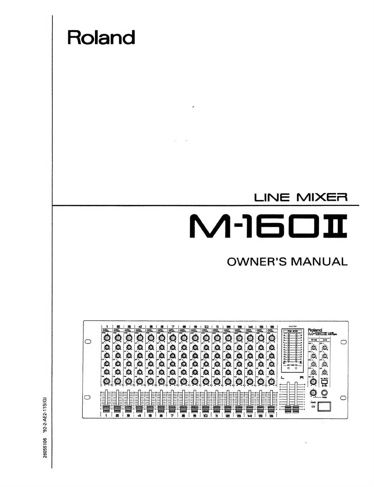
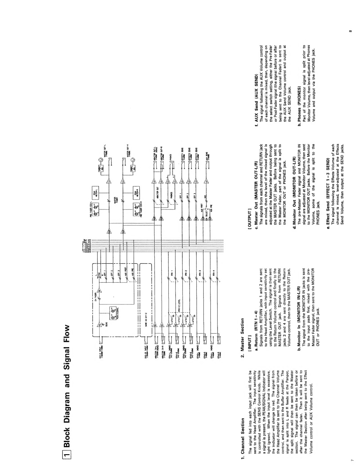
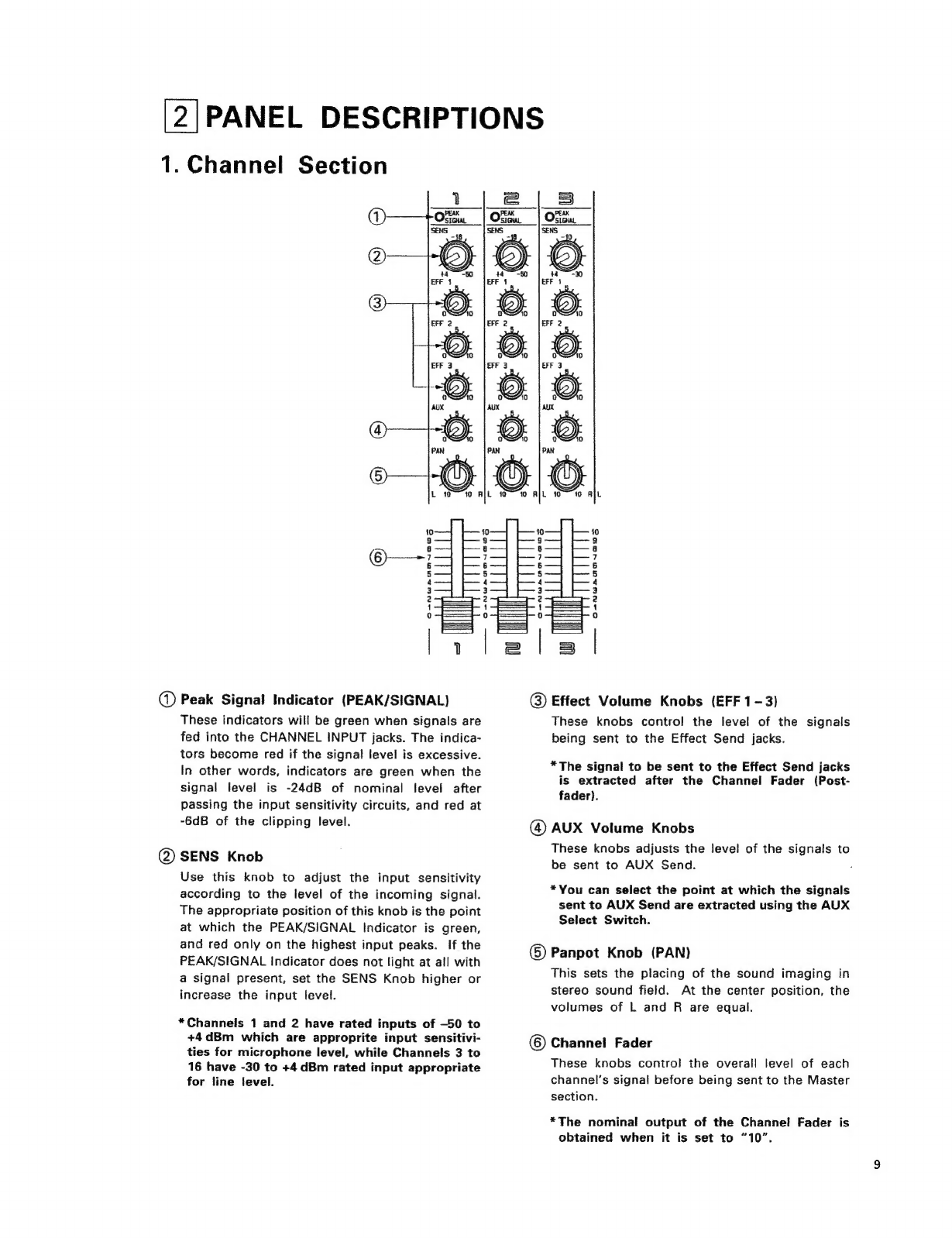
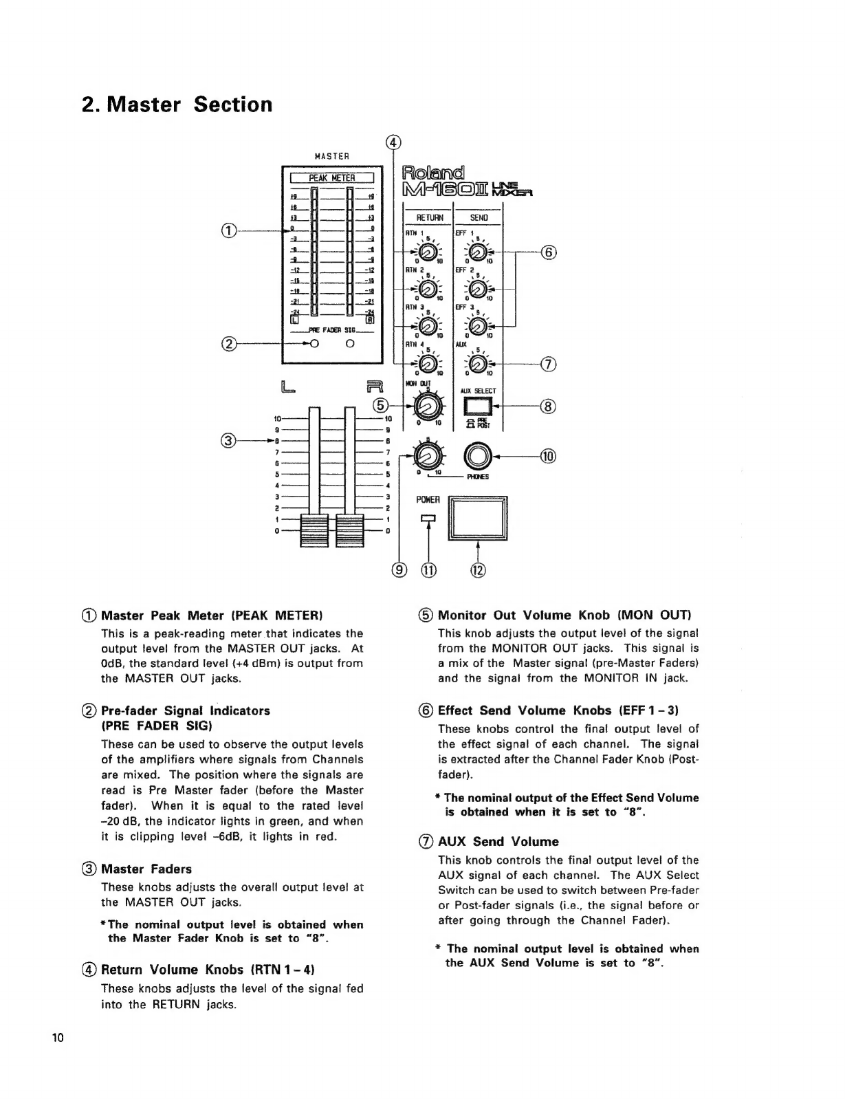
Roland M-160 II User manual
Other Roland Music Mixer manuals

Roland
Roland MC-909 User manual

Roland
Roland VS-880EX_OM User manual

Roland
Roland CPM-120 User manual

Roland
Roland Groovebox MC-505 Parts list manual

Roland
Roland Edirol M-10MX User manual

Roland
Roland PA-200 User manual

Roland
Roland SYSTEM-500 531 User manual

Roland
Roland PA-250 User manual

Roland
Roland Edirol M-16DX User manual

Roland
Roland Super Jupiter Programmer MPG-80 User manual

Roland
Roland Edirol V-8 User manual

Roland
Roland M-380 User manual

Roland
Roland M-120 User manual

Roland
Roland M-240 User manual

Roland
Roland M-48 User manual

Roland
Roland V-Mixer VM-C7100 User manual

Roland
Roland MC-909 User manual

Roland
Roland V-Mixer M-400 User manual

Roland
Roland V-Mixer VM-7200 User manual

Roland
Roland VM-7000 Series User manual


Popular Music Mixer manuals by other brands


Studiomaster
Studiomaster Air Pro 24 instruction manual

Pioneer
Pioneer SVM 1000 - Audio/Video Mixer Service manual

Yamaha
Yamaha MR1642 Operation manual

Ecler
Ecler MAC40v user manual

Pioneer
Pioneer DJM 909 - Battle Mixer W/Effects operating instructions

Veeder-Root
Veeder-Root TLS-350 Series System setup manual