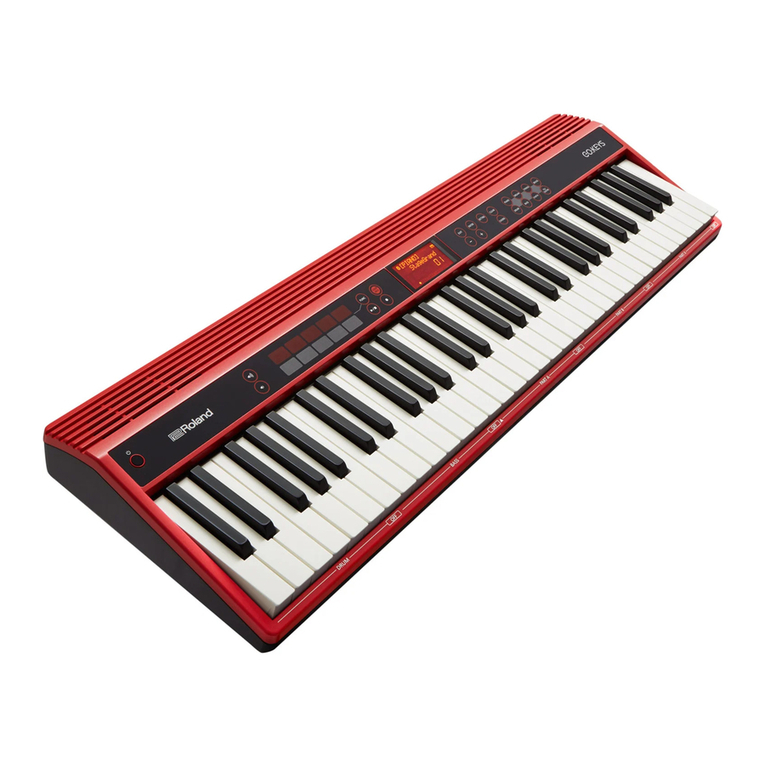
Roland E-X30 Operating and maintenance manual

SERVICE NOTES
Issued by RJA
Copyright © 2019 Roland Corporation
All rights reserved. No part of this publication may be reproduced in any form without the written permission
of Roland Corporation.
CC-KWS17057236E0
Jul. 2019 E-X30
Table of Contents
Cautionary Notes ..............................................................2
Specifications .....................................................................2
Exploded View ..................................................................4
Exploded View Parts List.................................................5
Accessories Parts List........................................................5
Connecting Wirings ..........................................................6
Checking the Serial Number ...........................................7
System Self-test..................................................................7

2
Jul. 2019 E-X30
Cautionary Notes
Before beginning the procedure, please read
through this document. The matters described may
differ according to the model.
User Data Cannot Be Backed Up
This product cannot back up user data to external media. And user data cannot
be written on paper.
Parts List
A component whose part code is ******** will not be supplied as a service part
because one of the following reasons applies.
• Because it is supplied as an assembled part (under a different part code).
• Because a number of circuit boards are grouped together and supplied as
a single circuit board (under a different part code).
• Because supply is prohibited due to copyright restrictions.
• Because reissuance is restricted.
• Because the part is made to order (at current market price).
• Because it is carried in electronic data on the Roland web site.
• Because it is a package or an accessory irrelevant to the function
maintenance of the main body.
• Because it can be replaced with an article on the market. (battery or etc.)
• Because it is sold as a product.
Roland Japan Warranty
Please send the problem report with followings when the defect occurred
within one year from production and within one month from the first
customer’s purchase.
• Model name:
• Serial number:
•Version:
• Purchase date by the first customer: yyyy/mm/dd
•Symptom:
• Frequency: always, sometimes or seldom
• Confirmed the symptom at your service dept: Yes/No
Specifications
Roland E-X30: Arranger Keyboard
Keyboard
61 keys (with velocity)
Sound Generator
Maximum Polyphony
256 voices
Parts
16 parts
Wave Memory
128 MB
Tones
Tones: 433 + 256 (GM2)
Drum Sets: 8 + 9 (GM2)
Effects
Reverb: 10 types
Chorus: 8 types
Transpose
-12– +12 (in semitones)
Octave
-2– +2
Arranger
Tempo
30–280
Styles
347 styles
One Touch Setting
4 settings/styles
with Tempo/Tone/Style/Transpose lock functions
Controls
START/STOP, SYNC START, INTRO/ENDING, FILL A, FILL B, FADE,
CHORD

3
Jul. 2019 E-X30
Scale Tunings
Scale Recall
12 user scale memories
User Scale Buttons
Instant quarter-tone tuning of each note of a scale (C–B)
Adjustable tuning range (-50– +50 cent) for each button
Tunings can also be saved to user program memories.
MP3 Pads
12 pads for MP3 playbacker via USB memory
Metronome
Beat
0, 2–9
Song
Internal Songs
160 songs
Recording
10 songs
MP3 playback
Others
Rated Power Output
10 W + 10 W
Speakers
Speakers: 10 cm (4 inches) x 2
Tweeters: 2.5 cm (1 inch) x 2
Controllers
Pitch bend wheel
Display
Custom LCD
Connectors
PHONES jack: stereo 1/4-inch phone type
OUTPUT (L/MONO, R) jacks: 1/4-inch phone type
MIC INPUT jack: 1/4-inch TRS phone type
SUSTAIN jack: 1/4-inch phone type
USB Computer port: USB B type
USB Memory port: USB A type
DC IN jack
Power Supply
AC adaptor
Current Draw
2 A
Dimensions
956 (W) x 360 (D) x 133 (H) mm
37-11/16 (W) x 14-3/16 (D) x 5-1/4 (H) inches
Weight (excluding AC adaptor)
6.2 kg
13 lbs 11 oz
Accessories
Owner’s Manual (#17042226, #17042227)
Leaflet “USING THE UNIT SAFELY” (#********)
AC adaptor (#17042220, #17042221, #17042222, #17042223, #17042224,
#17042225)
Music rest (#17042139)
Options (sold separately)
Pedal switch: DP series
* 0 dBu = 0.775 Vrms
* Printed matters will not be supplied after the end of the production. Then,
download the electronic file from the Roland web site.
* In the interest of product improvement, the specifications and/or appearance of
this unit are subject to change without prior notice.

4
Jul. 2019 E-X30
Exploded View
fig.bunkaizu.eps
5
2
9
9
11 11 11 11 11
12
15
10
10
14
13
16
7
4
3
8
6
1
13
16
14
15 17
11

5
Jul. 2019 E-X30
Exploded View Parts List
* When replacing No.10 RUBBER SWITCH 13P for other than the highest position (right end) of the keyboard, cut 1P to change 13P to 12P.
* When parts except above are necessary for repair, replace the product itself with a new one.
Accessories Parts List
No. Part Code Part Name Description Q’ty
1 17042212 ROTATE WHEEL ASSY 1
2 17042213 JACK BOARD ASSY 1
3 17042214 VOLUME BOARD ASSY 1
4 17042126 VOLUME KNOB 1
5 17042215 MAIN BOARD ASSY 1
6 17042216 ENCODER BOARD ASSY 1
7 17042129 ENCODER KNOB 1
8 17042217 FUNCTION BOARD ASSY 1
9 17042218 SPEAKER 2
10 17042230 TWEETER 2
11 17042210 RUBBER SWITCH 13P 5
12 17042219 KEYSCAN BOARD H+L WO/RUBBER SW 1
13 17042134 NATURAL KEY 3-KEY GROUP 5
14 17042135 NATURAL KEY 4-KEY GROUP 5
15 17042136 NATURAL KEY SINGLE 1
16 17042137 SHARP KEY 5
17 17042138 BATTERY COVER 1
Part Code Part Name Description Q’ty
17042139 MUSIC REST 1
17042226 OWNER’S MANUAL ENGLISH 1
17042227 OWNER’S MANUAL CHINESE 1
17042220 AC ADAPTOR FJ-SW1202000U (28) for 117VU/CS 1
17042221 AC ADAPTOR FJ-SW1202000E (32) for 230VEU 1
17042222 AC ADAPTOR FJ-SW1202000V (36) for 230VIN 1
17042223 AC ADAPTOR FJ-SW1202000B (49) for 230VE 1
17042224 AC ADAPTOR FJ-SW1202000C (65) for 220VCN 1
17042225 AC ADAPTOR FJ-SW1202000DR (26) for 117VBL 1

6
Jul. 2019 E-X30
Connecting Wirings
fig.wiring.eps
I/O Board J2 to J2 Keyboard CN14 (Right) to J4
Keyboard CN13(Left) to J3
Function Board J7 to J7
Function Board J5 to J5
I/O Board J1 to J1
I/O Board J1 to J10
I/O Board J9 to J9
I/O Board J8 to J8 J6 to Speakers (BLK/WHT to L ch, Red/BLK to R ch)
Encoder to J2
Main Board J7 to J7
Main Board J5 to J5
Pitch bender to J4
Volume to J1
I/O Board J3 to J3
Main Board J9 to J9 Main Board J2 to J2 Main Board J8 to J8
Battery to CN1 Main Board J1 and J10 to J1
Main board to other boards connection
Function board to other boards connection
I/O board to other boards connection
I/O board
CN1
J1
J2
J8
J9
Other boards
Battery
Main Board J1 and J10
Main Board J2
Main Board J8
Main Board J9
Main board
J2
J1
J3
J4
J5
J6
J7
J8
J9
J10
Other boards
I/O board J1
I/O board J1
I/O board J8
I/O board J9
I/O board J2
Keyboard CN13
Keyboard CN14
Speakers
Function board J5
Function board J7
Function board
J1 Volume
Encoder
I/O Board J3
Pitch bender
Main Board J5
Main Board J7
J2
J3
J4
J5
J7
Other boards

7
Jul. 2019 E-X30
Checking the Serial Number
Turn off the power, then press and hold STORE + M3 + M4 and then
press the power button to turn on the power.
Check the serial number.
System Self-test
Enter Self-testing Mode
Connect power supply, then press and hold STORE + M2 + M4 and then
press the power button to turn on the power.
* In the above step, it requires to press the power button so as to check the
functionality of this button.
Operation Procedures
The procedures are applicable to all test items.
To shift between the test items:
Next item:
Press and hold START/STOP button, then press (right side of
the panel) or
Press and hold START/STOP button, then rotate the data dial
clockwise.
Previous item:
Press and hold START/STOP button, then press or
Press and hold START/STOP button, then rotate the data dial
counter-clockwise.
To shift between the test procedures:
Next step:
Press or rotate the dial clockwise.
Previous step:
Press or rotate the dial counter-clockwise.
To start testing: (Test will start only when manually started)
Press 1button.
Device Information
When entered, the LCD will show the following image.
fig.test-device-info.eps
To turn the pages, press the / buttons.
Automatic Testing
When entered, the LCD will show the following image:
fig.test-auto-test.eps
The test includes:
USB flash drive (check the reading/writing function in the background)
Nor Flash (check the reading/writing function in the background)
SPI Flash (check the reading/writing/erasing function in the
background)
SDRAM (check the reading/writing function in the background)
Press the 1button to start testing; it will show all test results after the
testing.
* Before pressing the 1button, connect a USB flash drive to the USB connector
(TO DEVICE).
If there is an error in the item, it will show the ERR interface. Use the
/ to turn the pages.
The item that has not yet been tested will be marked with “----”.
If there is an error in the testing steps, the item name will be marked with
“*”.
fig.test-error-no.eps
If all are OK, the LCD will display the following image:
fig.test-ok.eps
Name Indication Format
Nor Software version NorFlash Vxxx, such as “V100”
SPI Music pack version SPIFlash Vxxx, such as “V100”
SN Serial no. SNXXXXXX, such as
“SN000001”
8
Jul. 2019 E-X30
LED
When entered, the LCD will show the following image:
fig.test-LED.eps
Testing procedures:
Press to switch to the next LED mode.
Press to switch to the previous LED mode.
Inspect the LED lighting status.
LED modes:
1. All lit in red.
2. All lit in green.
3. All lit in blue.
4. All lit in white.
5. All unlit.
LED panel layout:
fig.test-LED-panel.eps
LCD
When entered, the LCD will show the following image:
fig.test-LCD.eps
Testing procedures:
Press / to switch the LCD images; inspect the display effect.
Press to switch to the next image.
Press to switch to the previous image.
Pass: indicates the display effect is correct, no additional/lacking any pot,
the display content is clear.
Fail: any case other than the Pass one.
Test images:
1. Full LCD is lit.
2. Full LCD turns off.
3. The dot matrix area shows “>”.
fig.test-LCD-right.eps
4. The dot matrix area shows “<”.
fig.test-LCD-left.eps
5. The dot matrix area shows “#”.
fig.test-LCD-sharp.eps
6. The dot matrix area shows “8”.
fig.test-LCD-8.eps
7. The dot matrix area shows “X”.
fig.test-LCD-X.eps
Knobs (ADC)
When entered, the LCD will show the following image:
fig.test-volume.eps
During the operation, the LCD will indicate the current value.
Testing procedures:
1. Turn the corresponding knob to minimum.
Pass: hear a tone of “OK”
2. Turn the corresponding knob to maximum.
Pass: hear a tone of “OK”
3. Center (only for the controller that has a central value)
Pass: rotate/push the controller to the middle position, the LCD
shows a central value (64), then jump to the next item (this central
value of 64 has already been internally adjusted to include variations.
This figure must be 64.)
Follow the above procedures to test the knobs in the following sequence
(when a knob is finished testing, the system will automatically start the
next one. The LCD will indicate the test item.)

9
Jul. 2019 E-X30
Function Buttons
When entered, the LCD will show the following image:
fig.test-button.eps
Testing procedures:
Check the buttons strictly in the order form left to right, up to down, as indicated by the arrowhead in the image below.
Press the first button in this sequence to start testing the function buttons. At the same time, the LED of next button that is to be tested will be lit.
Pass: hear a pass tone.
Fail: hear a fail tone.
fig.test-button-order.eps
Data Dial
When the function button test is finished and passed, it will
automatically start the Data Dial test.
When entered, the LCD will show the following image:
Testing procedures:
1. Rotate the data dial clockwise to increase the value.
Pass: when the value increase to 10, hear a pass tone.
fig.test-dial-plus.eps
2. Rotate the data dial counter-clockwise to decrease the value.
Pass: when the value decrease to 0, hear a pass tone.
fig.test-dial-minus.eps

10
Jul. 2019 E-X30
Keys
* This test item cannot be skipped in the middle of executing.
When entered, the LCD will show the following image:
fig.test-key.eps
Testing procedures:
Press the keys strictly from right to left (indicated by the arrowhead in the image below) using medium touch force.
Pass: hear a pass tone.
Fail: When pressing a wrong key or the touch force is not within range, you will hear an error tone.
fig.test-key-keyboard.eps
The LCD shows the currently pressed key and the touch level.
fig.test-key-current.eps
Pedal
* Before entering this test item, connect the pedal switch to the SUSTAIN jack.
When entered, the LCD will show the following image:
fig.test-pedal.eps
Testing procedures:
Press the pedal.
Pass: hear a pass tone.
Fail: hear an error tone.
* If DP-2 is used, the pass or error tone sounds when releasing after pressing.

11
Jul. 2019 E-X30
Audio
When entered, the LCD will show the following image:
fig.test-audio.eps
* When connecting headphones, Phone is displayed.
* Note that sound is produced at high volume. It is recommended to
connect to the monitor speaker and adjust the volume.
* Pressing a key other than C4–C#5 will stop the sound.
Keys and the corresponding audio signals to be tested:
Testing procedures:
1. Disconnect the headphones.
Pass: the LCD shows “Speaker”
2. Press the corresponding keys to hear the audio sound (from speakers).
Pass: sound comes from speakers. No sound from headphones.
3. Connect the headphones.
Pass: the LCD shows “Phones”
4. Press the corresponding keys to hear the audio sound (from
headphones).
Pass: sound comes from headphones. No sound from speakers.
Turning Off
In this procedures, it requires to press the Power button to turn off the
instrument so as to check the functionality of this button.
Pass: it turn off the power.
Fail: it cannot turn off the power.
Other description
Aux Out and Mic: in normal mode, check the sound to see if they work
properly.
No. Key name Audio test signal LCD display
1C4 Left pan AUDIO CHECK PAN-
LEFT
2C#4 Right pan AUDIO CHECK PAN-
RIGHT
3D4
Max. undistorted signal
(L: 440 Hz sine wave, R:
1 kHz)
AUDIO CHECK LOSS-
LESS
4D#4 1 kHz sine wave AUDIO CHECK SINE-
WAVE-1KHz
5E4 Tone test signal
(Church Organ)
AUIDO CHECK
CHURCH-ORGAN
6F4 Sweep frequency signal
1 (range: 20 Hz–320 Hz)
AUDIO CHECK
SWEEP-FREQUENCE-
1
7F#4
Sweep frequency signal
2 (range: 320 Hz–4800
Hz)
AUDIO CHECK
SWEEP-FREQUENCE-
2
8G4 White noise AUDIO CHECK
WHITE-NOISE
9G#4 100 Hz sine wave AUDIO CHECK SINE-
WAVE-100Hz
10 A4 300 Hz sine wave AUDIO CHECK SINE-
WAVE-300Hz
11 A#4 400 Hz sine wave AUDIO CHECK SINE-
WAVE-400Hz
12 B4 10 kHz sine wave AUDIO CHECK SINE-
WAVE-10KHz
13 C5 AP test signal (IMD) AUDIO CHECK AP-
IMD
14 C#5 AP test signal (Multi-
tone)
AUDIO CHECK AP-
MULTITONE
Other manuals for E-X30
1
Table of contents
Other Roland Musical Instrument manuals

Roland
Roland DP-990 User manual

Roland
Roland DP-990F User manual

Roland
Roland RD-100 User manual

Roland
Roland Classic C-330 User manual

Roland
Roland HPi-7 User manual

Roland
Roland RD-170 User manual

Roland
Roland F-100 User manual

Roland
Roland FP-7F User manual

Roland
Roland HP237 User manual

Roland
Roland DP-900 User manual

Roland
Roland HP504 User manual

Roland
Roland GO:PIANO with Alexa Built-in User manual

Roland
Roland GO:PIANO User manual

Roland
Roland KR-777 User manual

Roland
Roland RD-200 User manual

Roland
Roland RD-1000 User manual

Roland
Roland VR-700 User manual

Roland
Roland PX-7B Operating and maintenance manual

Roland
Roland RMP-1 User manual

Roland
Roland RD-700GX User manual