Roland Carrie M.e User manual

Roland Carrie M.e
Owner‘s manual (including assembly instructions)
www.roland-werk.de

Carrie M.e
Diversity
Roland Carrie M.e basic model
comprises an aluminium frame,
aluminium base plate, low tow arm,
Weber e-coupling and safety ag.
Roland Carrie M.e basic model + rail
comprises an aluminium frame,
aluminium base plate, low tow arm,
Weber e-coupling, safety ag and rail
Roland Carrie M.e basic model
+ panels
comprises an aluminium frame,
aluminium base plate, low tow arm,
Weber e-coupling, safety ag and
1 set of panels
Roland Carrie M.e basic model +
double panels
comprises an aluminium frame,
aluminium base plate, low tow arm,
Weber e-coupling, safety ag and
2 sets of panels

Table of contents
1 Introduction 31
2 Safety instructions 32
3 Intended use 33
4 Riding safely 33
5 Loading safely 34
5.1 Transporting children 34
5.2 Transporting pets 34
6Before your rst ride / Before every ride 34
7 In the event of an accident 35
8 Legal provisions 35
8.1 Trailer lighting 35
8.2 Front facing 35
8.3 Rear facing 36
8.4 Side facing 36
8.5 Rear facing red light 36
9 Assembly 36
9.1 Unpacking 36
9.2 Package contents 37
9.3 Fitting the kickstand 38
9.4 Fitting the wheels 39
9.5 Fitting the tow arm to the coupling system 40
9.5.1 For use when cycling 41
9.5.2 For use as a handcart 42
9.5.2.1 T-bar for handcart use 43
9.6 Fitting the side panels 44
9.7 Fitting the front and rear panels 45
9.8 Fitting additional panels 46
9.9 Fitting the rail to the base plate 46
9.10 Fitting the rail to the panels 47
9.11 Fitting the lid 48
9.12 Fitting the tarpaulin 49
9.13 Fitting the safety ag 49
10 Trailer coupling on the bicycle 50
11 Maintenance and care 50
11.1 Replacing components 51
11.2 Rims/Tyres 51
11.3 Repairing a puncture 51
12 Technical data 51
13 Calculating tow arm load 52
14 Warranty and liability for defects 52
15 Environmental tips / Disposal 53
16 Legal notice 53
17 Trailer identication 54

4
Dear Customer,
We are delighted that you have decided to purchase our high-quality CARRIE M.e
bicycle trailer.
Its modular design allows you to set it up quickly and easily adapt it to suit your needs and
requirements. The Weber coupling technology ensures a secure connection link to your bicycle
and is suitable for pedelecs too.
Be sure to read this owner‘s manual carefully, keep it in a safe place and
follow all the steps described here.
All information in this manual relates to the design, technology, maintenance and
care of your CARRIE M.e bicycle trailer. Please follow this information,
much of it is relevant to safety – failure to observe it may lead to serious accidents and
nancial damage.
Anyone wishing to
• use,
• repair or maintain,
• clean,
• or dispose of
this trailer must have fully read and understood the contents and the meaning of this owner‘s manual.
If you have any further questions or have not fully understood something, do not hesitate to contact our
If you pass your trailer on to third parties, please provide them with this manual.
You may only put the trailer into operation once you have fully read, understood and implemented the con-
tents of this manual.
The manufacturer accepts no liability for damage resulting from non-compliance with the manual‘s instruc-
tions. You may only use your trailer for its intended use / the intended purpose.
Any other use may lead to malfunctions and accidents. Improper use will lead to the liability for defects and
warranty being invalidated.
Before your rst ride, be sure to read the chapter
„Before your rst ride / Before every ride“!
1 Introduction

5
You will nd four different types of instruction in this manual:
Note
This symbol provides information on the handling of the product or the respective part of the manual
to which special attention should be drawn.
Danger
This symbol indicates a possible danger to your life and health if the corresponding instructions for
action are not followed or if the appropriate precautions are not taken.
Caution
This symbol warns you that failure to follow the instructions will result in damage to property and the
environment.
Important screw joint
An exact torque must be applied here when tightening. To apply an exact tightening torque, you must
use a torque wrench. If you do not have a torque wrench, let a specialist workshop / expert carry out
this work! Parts that are not tightened correctly can work themselves loose or break! This can result
in the trailer tipping over heavily!
• one gives you important information about your new trailer and its use,
• one advises you of possible damage to property and the environment,
• the third type warns you about the possibility of the trailer tipping over and serious damage,
including injuries.
• the fourth prompts you to observe the correct torques so that parts cannot work themselves
loose or break.
Whenever you see these symbols, there is a risk that the danger described will occur! The instructions are
structured as follows:
2 Safety instructions

6
Read all warnings and information in this owner‘s manual carefully before using the trailer.
Dangers of improper use
Use your CARRIE M.e bicycle trailer only within the scope of its intended use described below.
Intended use also includes compliance with the maintenance and servicing requirements specied
in this manual. Also advise other users about the intended use and the dangers of non-compliance.
Improper use, overloading or lack of care can result in accidents causing serious injuries to you and
others!
Practice riding with your trailer and operating the brakes in a quiet and safe place before riding on
public roads. Protect yourself and others by riding responsibly.
Not all bicycles are suitable for towing a cargo trailer. Observe the instructions in your bicycle‘s
owner manual and/or ask a specialist bicycle retailer whether your bicycle is suitable for towing a
trailer. The bicycle must be in technically perfect condition and at least comply with national statutory
requirements.
The trailer is used exclusively for transporting goods and objects. It is not permitted to use the trailer
to carry people. Transported goods must be secured against slipping and tipping. Objects must not
protrude over the loading area. Statutory road trafc regulations must be observed when using the
trailer on public roads.
Use as a bicycle trailer: Max. permissible total weight 50 kg, max. permissible load 40 kg. Min.
support load approx. 0.3 kg, max. support load approx. 6.5 kg. When used as a handcart only, the
trailer can be loaded up to 100 kg.
When used in conjunction with an electrail e-drive retrot kit, the permissible gross weight may
change. You can obtain information on this from your specialist retailer or www.electrail.de.
If it is equipped as required by national statutory requirements, your trailer can be used on public
roads and on paved paths.
If you are not sure what your trailer‘s usage limits are, please contact our service centre
Information on use:
The manufacturer and retailer are not liable for any use outside the scope of intended use. This particularly
applies to non-compliance with the safety instructions and any resulting damage, for example due to:
• Always wear a tted and appropriate bicycle helmet.
Wear your helmet every time you ride, no matter how short the distance!
Consult the helmet manufacturer‘s instructions for the
correct t of the helmet.
• Always wear light-coloured clothing or sportswear with reective elements
when riding.
• Tight legwear is essential, use trouser clips if necessary.
• Your shoes should have non-slip and stiff soles.
• Never ride no-handed!
• off-road use,
• overloading or
• improper rectication of faults and defects.
Your trailer is not designed for extreme loads, such as riding over steps and kerbs.
3 Intended use
4 Riding safely

7
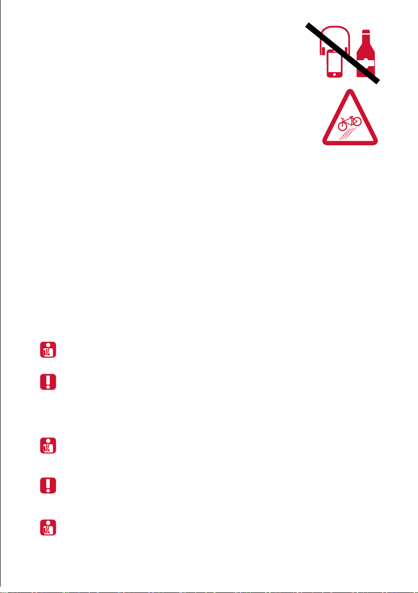
• Never cycle if you are unable to fully control your bike, especially if you
have taken any medication, alcohol or other drugs.
• Never ride wearing headphones.
• Do not talk on your phone while riding.
• If the road is wet or slippery and/or the trailer is fully loaded, adapt your riding
style accordingly. Slow down and brake cautiously and early, as your braking
distance is signicantly longer.
Special features when riding with a trailer
• When riding downhill, a laden trailer generates additional thrust forces.
This increases the braking distance too. Reduce your speed on sloping roads.
Never ride faster than 25 km/h, even when going downhill.
• Reduce your speed before corners, brake earlier and
ride carefully through the corners. Expect the steering to feel sluggish.
• The extra length of the trailer attached to your bike means the turning circle
is larger than you are used to when riding a bike or pedelec without a trailer.
• Ride a larger radius when riding through right-hand corners. The position of the
tow arm on the left of the trailer inhibits cornering.
• Riding over deep ruts on one side or driving over high kerbs and other obstacles
can cause the trailer to tip over.
• When cycling through narrow alleys, bear in mind that you need considerably more
space with a trailer than when cycling without a trailer.
• Make your trailer visible to other road users. Always t the brightly coloured safety
ag supplied.
5 Loading safely
5.1 Transporting children
5.2 Transporting pets
6 Before your rst ride / Before every ride
The trailer must be loaded within the permissible total weight range (see page 25).
Weight should be distributed evenly across the trailer, even with partial loads.
Overloading can lead to material breakage and the trailer to tip over!
Only load the vehicle on rm and level ground ensuring your bicycle and trailer cannot move. The
transported goods must be secured against slipping and tipping. Objects must not protrude over the
loading area. The centre of gravity of the entire load should be over the trailer‘s axle if possible and
kept as low as possible. An unfavourable weight distribution can have a negative effect on braking
characteristics and ride stability.
The trailer is intended exclusively for transporting goods and objects.
Transport of people is expressly prohibited!
The transport of animals is only permitted with suitable transport cages and xings. Please contact
your specialist retailer or contact our customer centre if you have any questions.
If you are not completely sure that your trailer is in perfect condition, do not ride. Have it checked by
a specialist retailer or contact our customer centre. If you use your trailer extensively, e.g. daily, have
all important components checked regularly by a specialist retailer.
Components may suddenly fail if you exceed their intended use or service life. This can lead to the
trailer tipping over and serious injury.

8
Read all warnings and notes in this owner‘s manual carefully before using the trailer.
Check your trailer for any changes. Aluminium components can break suddenly if they have been
deformed. Do not use any components that are deformed or bent, e.g. after the trailer has tipped
over. Always replace such components.
Before riding in road trafc, please inform yourself about the national statutory requirements. Be
sure to observe them. In Germany, this is regulated by the StVZO (German Road Trafc Licensing
Regulations) and the STVO (German Road Trafc Regulations).
Statutory requirements specify that lighting on the trailer should be designed as follows:
If you notice any changes on your trailer, DO NOT continue riding with it. Take the trailer to your
specialist retailer, describe how the trailer tipped over and have it checked!
Before your rst ride and then before each ride, check that:
• the coupling system is securely connected to the bike. The coupling must be tight and impossible
to twist,
• that the tyre pressure is at 2.5 bar. Information on the prescribed tyre pressure can also be found
on the side walls of the tyres. Adhere to the minimum and maximum pressure specications!
• the tyres and rims for damage, true running and any foreign bodies that may be stuck in them,
• the panels (and/or rail) are tightly screwed in place,
• the load is correctly distributed and secured,
• the lights work and are adequately charged.
• Test whether both wheels are seated correctly. Lift up the trailer on the right and left and
turn the wheels. The rim must run straight and true.
• Check whether the panels are broken or have been torn out of their xings.
An unsecured panel that can slip or come loose while riding can cause the trailer to tip over heavily
and injuries.
• Check that the connecting components (coupling and tow arm) between your bike and the trailer for
any cracks or fracture points.
• Check that the coupling is rmly attached.
1. If the trailer‘s width exceeds 600 mm:
Two white reectors mounted in pairs (max. 200 mm to outer edge).
2. If the trailer is wider than 1000 mm, a white light must also be tted on the
left-hand side.
3. If the trailer is less than 1000 mm wide, an additional white light may be installed.
7 In the event of an accident
8 Legal provisions
8.1 Trailer lighting
8.2 Front facing

9
1. If the trailer‘s width exceeds 600 mm:
A red tail light on the left-hand side.
2. Two red category „Z“ reectors, with a maximum distance of 200 mm to the outer edge.
1. Circular continuous retro-reective white stripes on tyres or rims or wheels; or
2. White retro-reective spokes (each spoke) or spoke sleeves (on each spoke) on each wheel or
3. At least two (180° apart) spoke reectors (yellow) on reecting to the side on each
wheel.
1. Regardless of the width of the trailer, additional red lights may be installed to the rear and on the
right-hand side and
2. Two additional red reectors (not triangular), max. 200 mm from the outer edge.
8.3 Rear facing
8.4 Side facing (both sides)
8.5 Rear facing red light
9 Assembly
9.1 Unpacking
Do NOT assemble the cargo trailer in the presence of children. They can get trapped in the
packaging material or swallow small parts and foils and choke on them.
Your trailer will be shipped in a special transport box.
This box is heavy.
Remove the transport protection material and
the cable ties with pliers or scissors.
Dispose of the packaging material according
to regulations and properly at the appropriate
disposal point.
Please proceed with care. Metal clips may have
been used to close the box. Be careful not to
injure yourself on these clips.
After you‘ve assembled the trailer and made the necessary settings, be sure to check that all
screw connections and fastenings are tight.
Its modular design allows you to set the trailer up quickly and easily adapt it to suit your
needs and purposes. Find a suitable space for assembling the trailer.
Basic model
Panels
(optional)

10
Basic model
Model with rail
(in addition to basic equipment):
9.2 Package contents
Immediately after unpacking, check that all the parts listed as supplied are actually present.
Basic equipment:
• 1 base plate with pre-assembled tow arm mount
• „Weber coupling“ tow arm
• 2 16-inch wheels with protective dust caps
• 1 safety ag
• Bracket for the ag
• Reector
• Non-slip mat
• „Roland“ sticker
• „Stopp“ sticker
• 1 6 mm Allen key
• Housing for the rear light
• Hinged bracket
• Name plate
• Quick-release clamp for the saddle mount
• 1 set of panels comprises:
- 2x front panels
- 2x rear panels
• 4 hinges
• 1 set of panels comprises:
- 2x front panels
- 2x rear panels
• 4 hinges
• 1 lid
• Rail
Model with panels
(in addition to basic equipment):
Model with panels
(in addition to basic equipment):

11
Basic model
Model with rail
(in addition to basic equipment):
• 1 set of panels comprises:
- 2x front panels
- 2x rear panels
• 4 hinges
• 1 set of panels comprises:
- 2x front panels
- 2x rear panels
• 4 hinges
• 1 lid
• Rail
Model with panels
(in addition to basic equipment):
Model with panels
(in addition to basic equipment):
Have the following parts to hand:
Base plate
Kickstand
Socket head
cap screws2 Springs
9.3 Fitting the kickstand
You will require a 5 mm Allen key to tighten the screws. To ensure you tighten to an exact
torque (9.5 Nm), you must use a torque wrench.
1. Place the base plate bottom side up on a at surface.
2. Position the kickstand so that the pre-drilled holes of the stand and the pre-drilled holes of
the base plate are on top of each other.

12
Have the following parts ready to hand:
Left-hand wheel
Fig. 1: Left-hand side in direction of travel
Fig. 2: Right-hand side in direction of travel
Right-hand wheel
3. Tighten the four screws with a 5 mm torque wrench
(tightening torque 9.5 Nm).
4. Hook the springs in the holes in the middle of the stand and the base plate.
9.4 Fitting the wheels
The wheels are labelled L / R (left / right). Make absolutely sure that the wheel labelled „R“ (Fig. 1) is
mounted on the right side of the trailer and the wheel labelled „L“ (Fig. 2) on the left side of the trailer
in the direction of travel.

13
1. Take the left-hand wheel in both hands. Press the button in the centre of the hub axle with your
thumb. Make sure that the metal washer is correctly positioned.
2. Push the wheel‘s clevis axle into the left-hand axle mount on the base plate as far as it will go.
Release your thumb from the button on the middle of the hub axle. The clevis axle must audibly
click into place.
3. Repeat this process for the right-hand wheel.
4. Then press the black protective rubber caps onto the hubs.
The tow arm supplied ts into the tow arm mount on the left-hand side
(when hitching to a bicycle) and the tow arm mount in the middle of the
trailer (when using the trailer as a handcart).
The tow arm will be difcult to insert into the tow arm mount
at rst. This improves after repeated use. You can spray the
end of the tow arm with a little silicone spray to make it easier
to insert.
Use silicone spray only, and do not use too much spray. This can attract dust and grains of sand
and cause damage to the guide rails.
Base plate overhead view in
direction of travel
Press
Press
Check that both wheels are securely in place.
To remove, press the button in the centre of the hub axle and pull off the wheel. Ensure the trailer is
unladen before removing the wheels.
9.5 Fitting the tow arm to the coupling system Quick-release clamp
Tow arm

14
To dismantle, open and loosen the quick-release clamp (1).
Press the safety button (2), and, at the same time, turn the tow arm
anti-clockwise until it stops (3). You can then pull the tow arm out
of the bracket (4).
Tow arm mount for bicycle set-up
Plastic bolt
Press safety button
Safety button
Quick-release clamp
Guide rail
Press
9.5.1 When hitching to a bicycle
1. Place the tow arm in the tow arm mount so that the black plastic bolts rest against the
mount‘s guide rails.
2. Press the locking button and push the tow arm into the tow arm mount as far as it will go.
3. Turn the tow arm clockwise until the safety button audibly locks into place and is visible on the side
of the tow arm mount. Then secure the tow arm using the quick-release clamp.
You are not permitted to use the trailer without the quick release.
4
2
3
1

15
3. Turn the tow arm clockwise until the safety button audibly clicks into place.
To dismantle, press the safety button (1) and at the same
time turn the tow arm anti-clockwise until it stops (2). You
can then pull the tow arm out of the bracket.
Tow arm mount for
handcart set-up
Guide rail
Press safety
button
Plastic bolt
9.5.2 Handcart set-up
1. Place the tow arm in the tow arm mount so that the black plastic bolts rest against the
mount‘s guide rails.
4. Press the locking button and push the tow arm into the tow arm mount as far as it will go.
2
Press
1

16
To dismantle, push the safety button on the plastic handle and turn the handle clockwise as far as it
will go. You can then pull the T-bar off the tow arm.
T-bar
Press safety
button
9.5.2.1 T-bar for handcart use
1. Press the safety button on the plastic handle of the tow arm.
Turn the handle clockwise until the bolt snaps back into place.
2. Push the T-bar into the tow arm‘s connector.
3. Then turn the plastic handle anti-clockwise until the safety button audibly and visibly engages.

17
Side panels
6 mm Allen key
1. Place a side panel on one long side of the base plate.
The black panel supports must face outwards.
2. Insert the panel‘s two guide pins into the base plate‘s locator holes.
3. Insert the supplied 6 mm Allen key into the opening at the top of the panel support.
To prevent damaging the thread, rst turn the inserted Allen key half a turn anti-clockwise.
The screw will then „drop“ into the thread. Tighten the panel‘s screws clockwise to a tightening
torque of approx. 3 Nm (hand-tight).
4. Simply repeat steps 1–4 to t the second side panel.
9.6 Mounting the side panels
Have the following parts to hand:

18
Front panel + rear panel
4 hinges
9.7 Fitting the front and rear panels
Have the following parts to hand:
1. Insert the tabs (1) of a rear panel into the mounting brackets (2) on the back of the base plate.
2. Fold the panel (3) upwards.
3. Fit the hinge‘s metal clips in the bracket provide in the side panel.
4. Close the hinge in the direction of the rear panel. Repeat the process on the other side of the
panel. This xes the rear panel in place.
5. Simply repeat the tting steps 1–4 described above to t the front panel.
1
2
2
1 1
3
2

19
If you want to increase the height of the panels, you will need add panels to the trailer.
Additional panels, accessories and spare parts can be purchased through our website.
To mount additional levels, simply follow the steps listed in the chapters
„Fitting the side panels“ and „Fitting the front and rear panels“.
Have the following parts to hand:
9.8 Mounting additional panels
9.9 Fitting the rail to the base plate
Have the following parts to hand:
Side panels Front panel + rear panel 6 mm
Allen keyl
4 hinges
6 mm Allen key
Rail
A loaded trailer must not exceed a maximum height of two metres.

20
Have the following parts to hand:
9.10 Fitting the rail to the panels
6 mm Allen key
Rail
2. Insert the 6 mm Allen key supplied into the apertures on the top side of the four panels. To prevent
damage to the thread, rst turn the Allen key half a turn to the left. The screw will then „drop“ into the
thread. Tighten the rail‘s screws clockwise to a tightening torque of approx. 3 Nm (hand-tight).
2. Insert the supplied 6 mm Allen key into the holes in the top of the
panel supports. Tighten the screws clockwise to a tightening torque
of approx. 3 Nm (hand-tight).
1. Insert the rail‘s four guide pins into the four locator holes on the base plate.
1. Insert the rail‘s four guide pins into the four locator holes on the panel supports.
This manual suits for next models
2
Table of contents
Popular Outdoor Cart manuals by other brands

ECR 4 Kids
ECR 4 Kids ELR-3044-XX quick start guide

Power Fist
Power Fist 8773335 user manual

Inter link
Inter link FRUITS 60 10 04 00 Assembling Instruction

Home Styles
Home Styles 4513-95 manual

GroundWork
GroundWork GW1100-2 owner's manual

Best Choice Products
Best Choice Products SKY1699 instruction manual