manuals.online logo
Brands
  1. Home
  2. •
  3. Brands
  4. •
  5. Roland
  6. •
  7. Recording Equipment
  8. •
  9. Roland MKS-80 User manual

Roland MKS-80 User manual

^Roland
MMSM SOUND MODULE
SUPER JUPITER
MIKm CZID
Owner's Manual
RADIO AND TELEVISION INTERFERENCE
"Warning -This equipment has been verified to comply with the limits for aClass Bcomputing
device, pursuant to Subpart J, of Part 15, of FCC rules. Operation with non-certified or non-verified
equipment is likely to result in interference to radio and TV reception."
The equipment described in this manual generates and uses radio-frequency energy. If it is not
installed and used properly, that is, in strict accordance with our instructions, it may cause interference
with radio and television reception.
This equipment has been tested and found to comply with the limits for aClass Bcomputing device
in accordance with the specifications in Subpart J, of Part 15, of FCC Rules. These rules are designed
to provide reasonable protection against such ainterference in aresidential installation.
However, there is no guarantee that the interference will not occur in aparticular instaliation. If this
equipment does cause interference to radio or television reception, which can be determined by
turning the equipment on and off, the user is encouraged to try to correct the interference by the
following measure:
•Disconnect other devices and their input/output cables one at atime. If the interference stops, it
is caused by either the other device or its I/O cable.
These devices usually require Roland designated shielded I/O cables. For Roland devices, you can
obtain the proper shielded cable from your dealer. For non Roland devices, contact the manufacturer
or dealer for assistance.
If your equipment does cause interference to radio or television reception, you can try to correct
the interference by using one or more of the following measures;
•Turn the TV or radio antenna until the interference stops.
•Move the equipment to one side or the other of the TV or radio.
•Move the equipment farther away from the TV or radio.
•Plug the equipment Into an outlet that is on adifferent circuit than the TV or radio. (That Is, make
certain the equipment and the radio or television set are on circuits controlled by different circuit
breakers or fuses.)
•Consider installing arooftoptelevision antenna with coaxial cable lead-in between the antenna and
TV.
If necessary, you should consult your dealer or an experienced radio/television technician for
additional suggestions. You may find helpful the following booklet prepared by the Federal Communi-
cations Commission;
"How to identify and Resolve Radio-TV Interference Problems"
This booklet Is available from the U.S. Government Printing Office, Washington, D. C, 20402,
Stock No.004-a00-00345-4.
Tl PANEL DESCRIPTION
^Receive Made indicator
©CantrasT Knob
Memory Area Switch
^Memory Cartridge Holder
MIDI Massage indicator
©Power Switch
M(D1 Channel Selector Switch
'Protect Switch
S/L Mode Switch
©MIDI Function SiMitcn
ODynamics Sens Knob
©Volurne Knob
WHMMC
NJ\S ttSM
IC
bD D
@Progrsrnmer Connector
10 Input Selector Switch
MIDI Connector
ITHRU/OUT/IN)
-J
"S"
Output Connector
<XLR)IUPPER/ LOWER)
Output Mode Switch
@Output Jack il/A Standard)
lUPPER/LOWERi
©Output Level Seiector Switch
The MKS-SO is an 8voice, 16 VCO polyphonic syn-
thesizer module that can be played by MIDI music
messages sent from the other MIDI device.
FEATURES
•The MKS-80 has memory capacity that retains
64 different tone coiors. By using the Memory
Cartridge M-64C that retains up to 128 tone
colors, total of 192 patch programs can be
available.
•The MKS-80 features battery backup system
that retains the data in memory even when
switched off.
•Auto Tune function that allows ail VCO's to be
instantaneously tuned just by pressing abutton.
•Patch Preset is aprogram that can contain atone
color (or even apair of tone colors depending on
the Key mode setting) and various mode and
effect settings.
•The Octave Shift function allows shifting the
pitch of the entire keyboard without changing
the VCO range.
•Data in the MKS-80's memory can be transferred
to another MKS-80 or to acomputer.
•The MKS-BO's dynamics function can change The
attack time as weli as the level.
•8y the unique Envelope Reset function, each
time you press anew key, the note wiH start
from the beginning of the envelope curve.
•By using the optionai Programmer MPG-80, syn-
thesizing will become much easier.
The Detune function enables apowerful ensemble
effect in Unison mode.
It is important to understand ail the functions
of the MKS-BO to make the best use of it.
Please read the separate volume "MIDI" and
this owner's manual.
CONTENTS
[fj Panel Description 3
A. Front Panel 3
B. Rear Panel 3
l2j Connection 6
J3] Operation 7
A. Outline of the IVIKS-80 7
B. Play Mode 8
a. MIDI Channel Setting 8
b. MIDI Function Switch 8
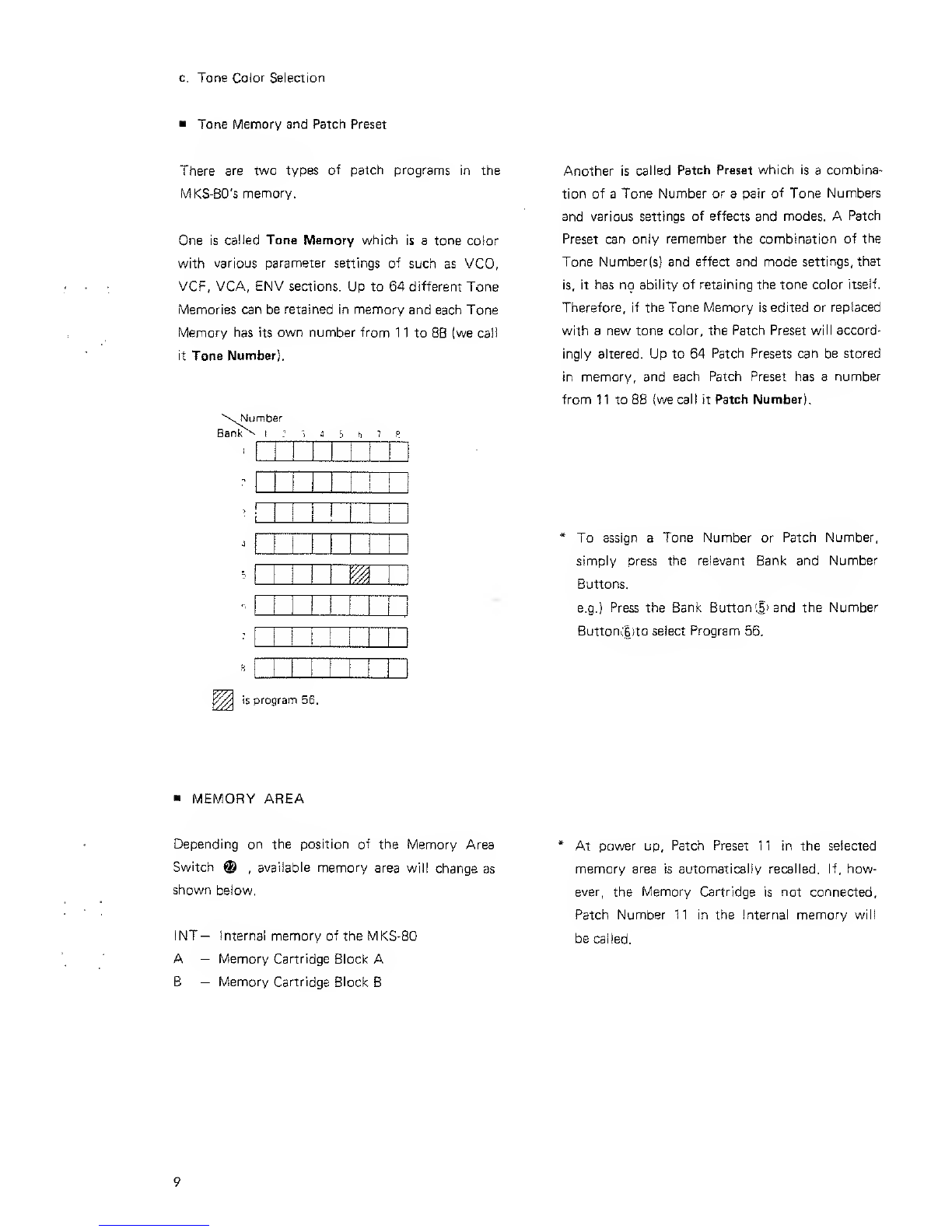
c. Tone Color Selection 9
1) Calling aPatch Preset 10
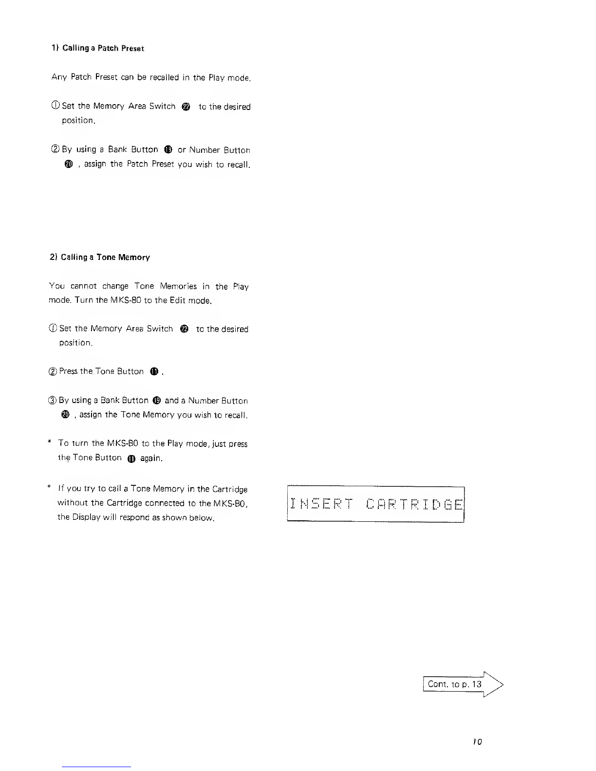
2) Calling aTone Memory 10
d. Auto Tune 13
e. Volume 13
f. Dynamics Sens Knob 13
g. Contrast Knob 13
C. Edit Mode (I) 14-20
a. Parameters of Tone Memory Section ... 14
b. Editing aTone Memory 21
c. Parameters of Patch Preset Section . . .22—25
d. Editing aPatch Preset 26
D. EditlVIode (II) 27
a. Setting up the Programmer MPG-80 .... 27
1) Programmer Connector 27
2) Connection 27
b. How to use the Programmer MPG-BO ... 28
1)Method 128
2! Method 229
E. Write Mode 30
a. Writing aTone Memory 30
b. Writing aPatch Preset 31
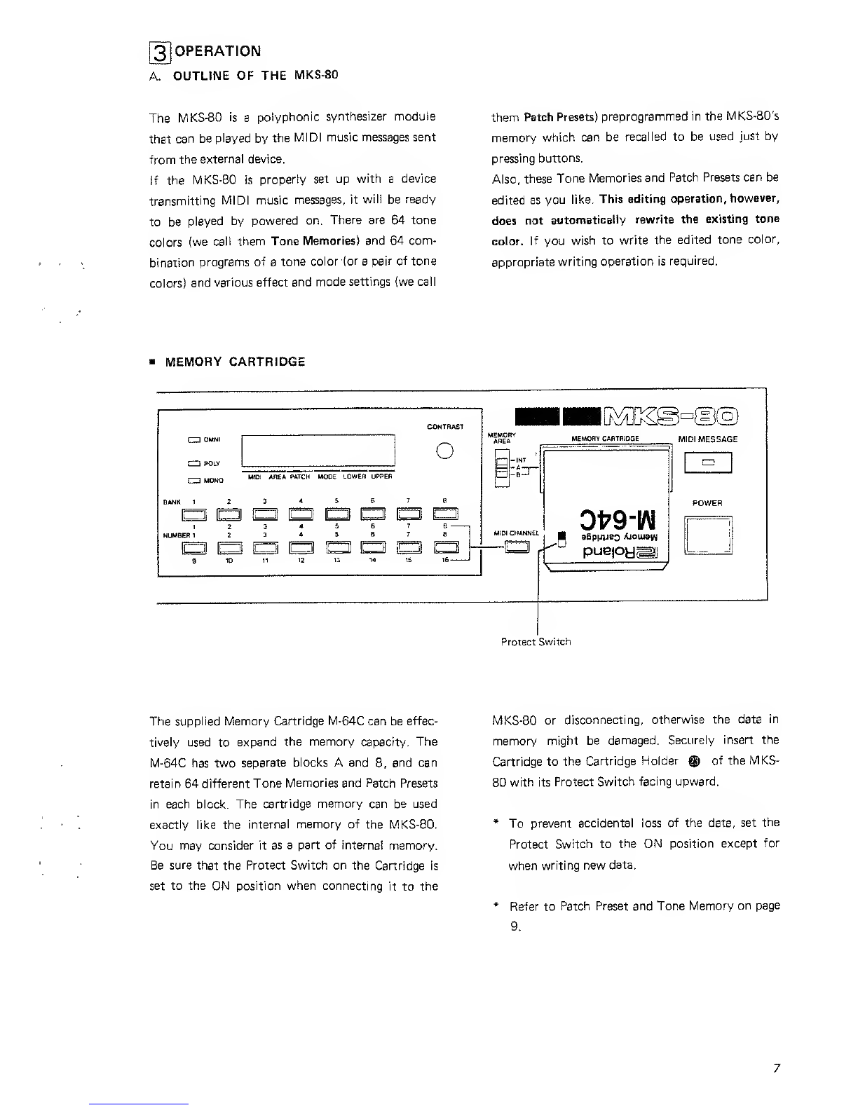
F. Memory Cartridge 32
a. Saving onto the Memory Cartridge 32
b. Loading from the Memory Cartridge ... 34
g] MIDI 36
A. Saving and Loading 36
a. Saving the data in the MKS-BO
to aMIDI device (or computer} 37
b. Loading the data in the MIDI device
(or computer) to the MKS-80 39
B. Indicators 40
a. Receive Mode Indicators 40
b. MIDI Message indicators 40
[5] Tables 41
Edit Map 11
Parameter Table 41
Display Message Table 44
Program Change Table 45
MIDI Function Table 46
\6\ Specifications 47
IMPORTANT NOTES
Before turning the MKS-80 on, make sure that
the Protect Switch ®is set to the ON position.
Otherwise the data in memory may be destroyed.
Power Supply Location
•The appropriate voltage to be used is shown on
the name piate on the rear panel. Be sure that it
meets the voltage system in your country.
•Do not use the same socket that is used for any
noise generating device, such as a motor, or varia-
ble lighting system.
•When setting up the MKS-80, be sure that all the
units are turned off.
•This unit might not work properly if turned on
immediately after turned off, or if the power
cable is plugged in with the unit turned on. If
this happens, simply turn the unit off, and turn it
on again in afew seconds.
•Operating the MKS-80 near aneon or fluorescent
lamp may cause noise interference. If so, change
the angle or position of the MKS-80.
•Avoid using the MKS-80 in extreme heat or
humidity or where it may be affected by dust.
Cleaning
•Use asoft cloth and clean on!y with amild
detergent.
•Do not use solvent-such as paint thinner.
•This unit might get hot while operating, but
there is nothing to worry about.
2l CONNECTION
LOWER UPPER
si- C3 CD
CD CZ!
O3
»-'
1
j
,,-, 1
'-— -—
en Cj CD CZl CD CD [li Ci
CD Cpip CpZZ! rp :^^J--
MID! IN
MIDI OUT
allllllllllllllllllllllllllllllliill
MPG-80 o
PDOCHlUUra
MID! IN MIDI OUT
fc^:^ t.;:?:i
Ampliflbr
6
MKB- 1000
JP-6
JUNO-105
MSQ700
MSO-!0C^etc
Amplifier
When the MKS-80 is used in monaural.set the Out-
put Mode Switch Qto the M\x position. \i it is set
to the U/L position, the MKS-80 may not sound at
all.
*Before setting up the units, mal<e sure that all the
units are turned off and the volume of the ampli-
fier is set to zero.
Input Selector Switch Q
This selects whether to receive the MIDI message
from the MIDI IN Jack or the Programmer Con-
nector. When not using the Programmer, set It to
the MIDI position, if it is set to the Programmer
position, the message received from the MIDI IN
will be ignored.
3] OPERATION
A. OUTLINE OF THE MKS-SO
The MKS-80 is apolyphonic syntiiesizer module
that can be played by the MIDI music messages sent
from the external device.
If the MKS-80 is properly set up with adevice
transmitting MIDI music messages, it will be ready
to be played by powered on. There are 64 tone
colors (we call them Tone Memories) and 64 com-
bination programs of atone color (or apair of tone
colors) and various effect and mode settings (we call
them Patch Presets) preprogrammed in the MKS-80's
memory which can be recalled to be used just by
pressing buttons.
Also, these Tone Memories and Patch Presets can be
edited as you like. This editing operation, however,
does not automatically rewrite the existing tone
color. If you wish to write the edited tone color,
appropriate writing operation is required.
MEMORY CARTRIDGE
CD POLV
r~i MONO
O
MIDI AHEA MTCH MODE LOWER UPPER
CZ! t^
ini
[^ ID^
-INT
MIDI CHANNEL
MEMORY CARTRIDQE MfDI MESSAGE
0fr9-
puepy^j
CD
Protect Switch
The supplied Memory Cartridge M-64C can be effec-
tively used to expand the memory capacity. The
M-64C has two separate blocks Aand B, and can
retain 64 different Tone Memories and Patch Presets
in each block. The cartridge memory can be used
exactly like the internal memory of the MKS-80.
You may consider it as a part of internal memory.
Be sure that the Protect Switch on the Cartridge Is
set to the ON position when connecting it to the
MKS-80 or disconnecting, otherwise the data in
memory might be damaged. Securely insert the
Cartridge to the Cartridge Holder ®of the MKS-
80 with its Protect Switch facing upward.
*To prevent accidental loss of the data, set the
Protect Switch to the ON position except for
when writing new data.
*Refer to Patch Preset and Tone Memory on page
B. PLAY MODE
Make sure that all the connections have been cor-
rectly made, and turn on the MKS-80,then the key-
board, and finally the amplifier. Now, the MKS-80's
Display Window shows AUTO TUNE, all the 16
VCO's being automatically tuned. And soon, the
Display will respond as shown right.
At this stage, if the MKS-80 receives the message on
the same MIDI Channel as shown at "a" in the Dis-
play, it will operate. While the MKS-80 is receiving
any message, the MIDI Message Indicator is lighted.
If the message is transmitted on adifferent channel,
the MKS-80 cannot receive the message, therefore,
the indicator stays dark.
The leners "a" to "f" represent the following
elemenis.
aMIDI Channel
bMemory Area
I-Interna! Memory (INT)
A-Memory Canridge (A)
B-Memory Cartridge (Bl
cPatch Number
dKey Mode
W-. Whole
S2- Split 2
SI -Split 1
D-Dual
eLower Tone Number
fUpper Tone Number
a. MIDI Channel Setting
©Press the MID! Channel Button ®,and the dis-
play will respond as shown right.
(2) While holding the MIDI Channel Button ,
assign the MID! Channel by pressing aBank But-
ton (E) and aNumber Button ®.The Display
shows the selected MIDI Channel in blue num-
bers.
*DD represent the MIDI Channel currently
remembered in memory.
*The set MID! Channel is remembered even after
power off, so the next time the MKS-80 is
powered on, the previous MIDI Channel remains.
b. MIDI Function Switch
With this switch, you can select which of the MIDI
function to be used.
To prevent improper operation, select either the
Ior II position. The HI position is to be selected
only for aspecial purpose (Exciusive Message).
*For the details of the
refer to page 46.
IDI Function Switch,
c. Tone Color Selection
Tone Memory and Patch Preset
There are two types of patch programs in the
l\^KS-80's memory.
One is called Tone Memory which is atone color
with various parameter settings of such as VCO,
VCF, VGA, ENV sections. Up to 64 different Tone
Memories can be retained in memory and each Tone
Memory has its own number from 1 1 to SB (we call
it Tone Number).
Number
Bank t'J "^ J5 h 7P
Another is called Patch Preset which is acombina-
tion of aTone Number or apair of Tone Numbers
and various settings of effects and modes. APatch
Preset can only remember the combination of the
Tone Numberls} and effect and mode settings, that
is, it has no ability of retaining the tone color itself.
Therefore, if the Tone Memory is edited or replaced
with anew tone color, the Patch Preset will accord-
ingly altered. Up to 64 Patch Presets cah be stored
in memory, and each Patch Preset has anumber
from nto 88 (we call it Patch Number),
*To assign aTone Number or Patch Number,
simply press the relevant Bank and Number
Buttons.
e.g.) Press the Bank Button (.1) and the Number
Button.:6;to select Program 56.
is program 56.
«MEMORY AREA
Depending on the position of the Memory Area
Switch ®,available memory area will change as
shown beiow.
INT- Internal memory of the MKS-80
A-Memory Cartridge Block A
B—Memory Cartridge Block B
*At power up, Patch Preset 1 1 in the selected
memory area is automatically recalled. If, how-
ever, the Memory Cartridge is not connected.
Patch Number 11 in the Internal memory will
be called.
1} Calling aPatch Preset
Any Patch Preset can be recalled in the Play mode.
®Set the Memory Area Switch ®to the desired
position.
d) By using aBank Button ©or Number Button
®,assign the Patch Preset you wish to recall.
2) Calling aTone Memory
You cannot change Tone Memories in the Play
mode. Turn the MKS-80 to the Edit mode.
(D Set the Memory Area Switch @to the desired
position.
(2) Press the Tone Button <D .
Q) By using aBank Button (£) and aNumber Button
®,assign the Tone Memory you wish to recall.
*To turn the MKS-BO to the Play mode, just press
the Tone Button (ff again.
*If you try to call aTone Memory in the Cartridge
without the Cartridge connected to the MKS-80,
the Display will respond as shown below.
Cont, to p. 13
70
KEDIT MAP
f^Rc3land SURER JUi=ITeR
:Be0 g|
EDIT MAP
0=EJ Hi 0=0
Dm ^v,. i_.-iir-.ii-/ 1-1-/ IE" M=\L
"'
[won
—now hOlH
;: IB IE-•xfi7,IE]t.lS
HAHOE
1^1
niME WW
/ \
•hCU
EMV-3
]=H!e£B; M-
nHQHBH
\I /
n
M^M: S3 ^
Sir
t \
1A","^'A T"
1' "~^'
_________ „,
\1/
PROGRAMMER
ISRoiand surer juriter rrogrrmmer
IBQISSH
I
[^[^©-,13©
])
12
d. Auto Tune f. Dynamics Sens Knob
Ail 16 VCO's will be instantaneously tuned just by
flick of aswitch even during live performance.
*At power up, the Auto Tune function will auto-
matically work. When the MKS-80 Is not warmed
up enough, the pitches are unstable. Press the
Auto Tune Button @when the MKS-80 is well
warmed.
Even if this knob is raised, there will be no dynam-
ics effect obtained, unless the dynamics is turned on
in the Tone Memory currently in use.
*The values of the Dynamics and Volume cannot
be written into memory.
To tune the MKS-80 with other musical instru-
ment, adjust the Tune Knob Owhich is variable
within ±50 cent (±1/4 tone).
g. Contrast Knob
This adjusts the contrast of the Display Window.
e. Volume Knob
This controls the overall volume of the MKS-80, and
the headphones volume.
ITune Knob
©Auto Tune Button ©Contrast Knob
ODynamics Sens Knob
©Volume Knob
©Headphones Jack
13
C. EDIT MODE (I)
Like any analog synthesizer, tine MKS-80 has various
parameters wfiicln can be edited for sound synthesis.
The MKS-80, however, does not feature l<nobs or
svi/itches on its panel for you to touch or move,
instead, there are two methods of synthesizing. One
is ceiling each parameter and changing its value by
using the panel buttons on the [VlKS-80. Another is
by using the optional programmer MPG-BO which
works just like panel controis of asynthesizer.
The Edit function does not automatically rewrite
the existing program, unless the appropriate proce-
dure for rewriting Is done.
a. Parameters of Tone Memory Section
All the parameters in the Tone Section can be used
to edit aTone Memory.
See the Edit Map on p. n,too.
LFO-1 This is aLow Frequency Oscillator which controls the VCO and VCF, etc.
LFO Rate (0-100) PI LFO Waveform (Oi, k, Pu ,RND)
This controls the rate of the LFO-1. At zero, ob-
tained rate is the slowest, and as the value is in-
creased, the rate is quickens.
This is to select the output waveform of the LFO-1
There are four types of waveforms optional.
gj LFO Delay Time (0-100)
This sets the time required for the LFO-1 to start
its modulation after akey is pressed on the key-
board. At zero, there is no delay time.
14
VCO Modulation VCO's frequency can be controlled by the LFO-1 or ENV-1
.
VCO Modulation LFO-1 Depth (0-100) VCO Modulation ENV-1 Depth (0-100)
When the LFO-1 is modulating the VCO's frequen-
cy, this value decides the intensity of the modula-
tion. At zero, there is no modulation obtained, and
as the value is increased, deeper pitch modulation
is obtained.
When the ENV-1 is controlling the VCO's frequen-
cy, the value set here decides the intensity of the
modulation. At zero, there is no modulation, and as
the value is increased, deeper pitch moduiation is
obtained.
Pulse Width Modulation The ratio of the VCO's pulse vwave can be altered by ENV-1 ,LFO-1 or keyboard.
Pulse Width (0-100) gj PWM Mode Selector (ENV, LFO, KYBD)
This sets the ratio of the VCO's pulse wave. At 0,
pulse width ratio is 50%, making asquare wave. And
as you increase the value, the pulse width will be-
come narrower, the sound disappearing just before
100%.
PWM (0-100)
The ratio of the pulse wave set with the Pulse Width
Qcan be modulated by the ENV-1 ,LFO or key-
board. The PWM Knob decides the intensity of the
moduiation. At value zero, there is no modulation,
and as the value goes up, deeper modulation is
obtained.
This selects which one of the ENV-1 ,LFO-1 or the
keyboard modulates the pulse width.
*Moduiating pulse width by keyboard
The width of pulse wave generated from the
MKS-80 can be changed depending on the key
you play. If all the pulses are set exactly the
same ratio, higher note may sound thin. To solve
this problem, it is agood idea to set the pulse in
the higher pitch to wider.
[0 PWM Polarity (NRM, INV)
This selects the polarity of the waveform or enve-
lope curve that controls PWM. For instance, if using
the ENV-1 for modulation, the pulse width gets
wider in the Normal, and narrower in the Invert
mode.
75
VCO Key Follow In the VCO section, Key Follow function is provided to detune the generated sound.
This also can be effectively used during synthesizing with Cross Modulation function.
VCO Key Follow (0-100) [g VCO Selector (1, OFF, 2)
This is usually set to 100%, but can be set to any
value you like from to 100%. At 0%, the pitch
obtained will be always the same regardless of which
key is pressed. And as you increase the value, the
pitch alteration will be more drastic.
With this, you can select which of the VCO-1 or 2
should take on the Key Follow effect set at the
VCO Key Follow. At OFF, both VCO-1 and 2take
on 100% Key Follow.
Cross Modulation Here, the output waveform from the VCO-2 changes the VCO-1 's pitch. With the
VCO-2 set to the Low Frequency, complicated pitch alteration can be obtained
with combination of the LFO-1
.
Cross Modulation Manual Depth {0-1001 [Q Cross Modulation Polarity (NRM, INV]
The Intensity of the Cross Modulation can be
manually changed. At 0, there is no effect obtained,
and increasing the value will deepen the pitch
alteration.
This selects the polarity of the ENV-1 output set
above. In Normal, the ENV curve starts from zero
to its maximum, and at Invert, the curve will reach
to zero finally.
10 Cross Modulation ENV-1 Depth (0-100)
This decides the amount of ENV-1 's output sent
to the Cross Modulation. At 100, maximum effect
is obtained.
VCO-1
[0 VCO-1 Modulation (NRM, OFF, INV)
This controls ON/OFF of the VCO-1 Modulation.
In Normal, higher CV makes higher pitch, and in
Invert, the other way round.
76
VCO-1 Range (32C-2C) RVCO-1 Waveform {%.p.. ,JU .Rf
This selects the pitch of the VCO-I in half tone step
from 32' to 2'. The Display Window shows the
note represented by MIDI Key number 60 (which
corresponds with Middle Cof the piano keyboard}.
This selects the output waveform from the VCO-1,
Synchro By synchronizing two VCO's, complicated waveform, which is impossible to make with asingle
VCO. can be created.
[0 VCO SYNC (1 ^2, OFF, 1^2)
This controls ON/OFF of the VCO synchro, and
its direction.
VCO-2 By mixing this with VCO-1, or using Synchro or Cross Modulation function, wide variety of
sound synthesis is possible.
mVCO-2 Modulation (NRM, OFF, ilMV; VCO-2 Fine Tune
This selects the ON/OFF of the VCO'2 modulation.
!n Normal, higher CV makes higher pitch, and in
Invert, the other way round,
g| VCO-2 Range (LOW,32C-2C, HI)
This selects the pitch of the VCO-2 in half tone
step from 32' to 2', and also selects Low or High
Frequency. The Display Window shows the note
represented by MIDI Key number 60 (which cor-
responds with Middle Cof the piano keyboard).
This is the VCO-2's tuning function ranging from
-50to-t-50cents (±1/4 tone).
g] VCO-2 Waveform (<U, [\ ,|J ,NIS)
This selects the output waveform of the VCO-2.
lixer
gg Source Mixer (0-100)
This sets the proportion of the signal from the
VCO-1 and 2. At 0, only the VCO-1 sound is heard,
and as the value increases, the proportion of the
VCO-2 increases, and at 100, only the VCO-2 sound
is obtained.
77
High Pass Filter Tlnis filter iets the high frequency harmonics pass and cuts off the low harmonics.
g0 High Pass Fitter Cutoff Frequency
This sets the cutoff point of the HPF. As the value
is increased, lower frequency is cut off.
VCF This filter changes the tone color by cutting off or emphasizing harmonics. This filter lets the low
frequency harmonics pass and cuts off the high frequency. Also the cutoff frequency of this filter
is controlled by the LFO or Envelope.
VCF Cutoff Frequency (O-IOO) HVCF Modulation ENV Depth (0-100)
This controls the cutoff frequency of the VCF.
At 100, the original waveform passes without being
changed, and as the value is decreases, higher fre-
quency is cutoff.
^VCF Resonance (0-100}
This sets the amount of Envelope which controls
the cutoff frequency. At 0, there is no effect, and
as the value increases, the modulation becomes
more intensive.
SH VCF Modulation LFO Depth (0-100)
This emphasizes the cutoff point set with the Cutoff
Frequency ^. At 0, there is no effect, and as you
raise the value, certain harmonics are emphasized,
and created sound will become more unusual, more
electronic in nature.
|g] VCF Envelope Selector (EG1, EG2)
This selects which of ENV-1 or 2controis the VCF.
10 VCF Envelope Polarity (NRM, INV)
This selects the polarity of the envelope curve that
controls the VCF. At Normal the curve goes up
from zero up to its maximum.
This sets the amount of the LFO-1 that controls the
cutoff frequency of the VCF. At 0, there is no
effect and as the value increases the modulation
becomes more intensive.
ig VCF Key Follow (0-100)
The cutoff frequency of the VCF can be changed
depending on the key pressed. At 0, however, the
cutoff frequency does not change at all. At 100,
the cutoff frequency wit! fully change according to
the pitch of the key pressed.
VGA This controls the volume (amplitude) of the sound.
ES VCA Level (0 to 1001 gj] VCA Modulation LFO-1 Depth
This sets the level of the ENV-2 that controls the
VCA, so it should be set considering the volume
difference caused in changing the tone colors.
This sets the amount of the LFO-1 that control the
VCA ievel. At 0, there is no effect, and as the value
is increased, the amount of the signal increases.
Dynamics This is to change the level or attack time of the envelope by the velocity of key pressure.
The message which controls dynamics is Ml Di Key Velocity.
Dynamics Time (0 to 100) Dynamics Level (0 to 100)
This decides the amount of the Key Velocity that
controls attack time of the envelope. At 0, the
attack time remains at its set level, and as the value
is increased, attack time gets shorter by harder key
attack.
This decides the amount of the Key Velocity that
controls the level of envelope. At 0, the level re-
mains at its set level however hard the key is at-
tacked. But as the value is increased, the envelope
level changes more obviously depending on how
you play the keyboard, that is, the harder you
attack the key, the higher the level will be.
Envelope This section processes the gate signal generated by Key ON/OFF to control VCF, VCO, etc.
Basicaiiy, it consists of Attack Time, Decay Time, Sustain Level and Release Time.
Envelope Reset (ON, OFF) ?i] ENV-1 Dynamics (ON, OFF)
This selects whether to start each note from the
beginning of the envelope curve, or continue the
curve from the present level. When it is ON, each
time you press anew key, the note will start from
the beginning of the envelope curve.
Eg ENV-2 Dynamics (ON, OFF)
These two are both to select whether to control the
envelope with Key Velocity message or not.
79
ENV-1 Attack Time (0-100) ENV-2 Release Time (0-100)
ENV-2 Attacl< Time (0-100) mENV-2 Release Time (D-1 00)
TInese set tlie time required for thie signal to reach
its maximum from the moment the key is pressed
down. At 0, the shortest attack time is obtained.
These determine the time needed for the voitege
to reach zero from the moment the key is turned
OFF. At 0, the shortest release time is obtained.
mENV-1 Decay Time (0-100) ENV-1 Key Follow (0-100)
mENV-2 Decay Time (0-100) U\ ENV-2 Key Follow (0-100)
These adjust the time needed for the signal to
drop from the maximum to the sustain level. At
0, the quickest decay time is obtained.
*When the sustain level Is set to 100, the enve-
lope curve does not. change by the decay time
setting.
The time required for the envelope to complete
its curve can be changed depending on which key
is pressed. There is no change of the time at all
when the Key Follow is set to 0, but as the value
is increased, envelope time becomes shorter with
higher key pressed.
HI ENV-1 Sustain Level (0-100)
Ug ENV-2 Sustain Level (0-100)
This determines the sustain level to which the signal
falls at the end of the decay time.
At 100, thisequals to the peak level of the envelope
curve.
20

Other manuals for MKS-80

2

Other Roland Recording Equipment manuals

Roland Planet-P  MKS-10 User manual

Roland

Roland Planet-P MKS-10 User manual

Roland GK-2A User manual

Roland

Roland GK-2A User manual

Roland VP-70 User manual

Roland

Roland VP-70 User manual

Roland Texart RT-640 User manual

Roland

Roland Texart RT-640 User manual

Roland R-09HR User manual

Roland

Roland R-09HR User manual

Roland GK-3B User manual

Roland

Roland GK-3B User manual

Roland SVC-350 Operating and maintenance manual

Roland

Roland SVC-350 Operating and maintenance manual

Roland Octa-Capture User manual

Roland

Roland Octa-Capture User manual

Roland Boutique JU-06 User manual

Roland

Roland Boutique JU-06 User manual

Roland MT-200 User manual

Roland

Roland MT-200 User manual

Roland DM-80 User manual

Roland

Roland DM-80 User manual

Roland S-750 User manual

Roland

Roland S-750 User manual

Roland CD-2e Manual

Roland

Roland CD-2e Manual

Roland Studio-Capture Amplifier User manual

Roland

Roland Studio-Capture Amplifier User manual

Roland XV-3080 Operating and maintenance manual

Roland

Roland XV-3080 Operating and maintenance manual

Roland V-Bass VB-99 User manual

Roland

Roland V-Bass VB-99 User manual

Roland VP-03 User manual

Roland

Roland VP-03 User manual

Roland MPU-101 Installation and operation manual

Roland

Roland MPU-101 Installation and operation manual

Roland MV-8800 Production Studio User manual

Roland

Roland MV-8800 Production Studio User manual

Roland SPD-S User manual

Roland

Roland SPD-S User manual

Roland AF-70 User manual

Roland

Roland AF-70 User manual

Roland S-770 User manual

Roland

Roland S-770 User manual

Roland RA-50 User manual

Roland

Roland RA-50 User manual

Roland TR-08 User manual

Roland

Roland TR-08 User manual

Popular Recording Equipment manuals by other brands

Siemens N148/23 manual

Siemens

Siemens N148/23 manual

Super Circuits AVSI-11 Setup and user guide

Super Circuits

Super Circuits AVSI-11 Setup and user guide

Yamaha MDR-1 Handling instructions

Yamaha

Yamaha MDR-1 Handling instructions

Eventide VR240 Quick reference guide

Eventide

Eventide VR240 Quick reference guide

DMT 101321 user manual

DMT

DMT 101321 user manual

Bosch Rexroth IMmtcp manual

Bosch

Bosch Rexroth IMmtcp manual

Berbel ConInterface installation instructions

Berbel

Berbel ConInterface installation instructions

Ekinex EK-EH2-TP quick start guide

Ekinex

Ekinex EK-EH2-TP quick start guide

Valeton GP-100 user manual

Valeton

Valeton GP-100 user manual

SST SST-DN3-104 Hardware reference guide

SST

SST SST-DN3-104 Hardware reference guide

Akai EWI 1000 Service manual

Akai

Akai EWI 1000 Service manual

TC-Helicon GO XLR quick start guide

TC-Helicon

TC-Helicon GO XLR quick start guide

Behringer ULTRA-DI PRO DI800 Technical specifications

Behringer

Behringer ULTRA-DI PRO DI800 Technical specifications

Belkin TuneStudio user manual

Belkin

Belkin TuneStudio user manual

Blackstar Amplification Carry-on FOLDING CONTROLLER 25 owner's manual

Blackstar Amplification

Blackstar Amplification Carry-on FOLDING CONTROLLER 25 owner's manual

Sonifex Dante AVN-AIO4 Handbook

Sonifex

Sonifex Dante AVN-AIO4 Handbook

AudioScience lyo Dante 8.8M manual

AudioScience

AudioScience lyo Dante 8.8M manual

Atmark Techno Armadillo-400 Series Hardware manual

Atmark Techno

Atmark Techno Armadillo-400 Series Hardware manual

manuals.online logo
manuals.online logoBrands
  • About & Mission
  • Contact us
  • Privacy Policy
  • Terms and Conditions

Copyright 2025 Manuals.Online. All Rights Reserved.