manuals.online logo
Brands
  1. Home
  2. •
  3. Brands
  4. •
  5. Rolls
  6. •
  7. Amplifier
  8. •
  9. Rolls PM55 User manual

Rolls PM55 User manual

PM55 Personal Monitor Station
Rolls Corporation
Salt Lake City, UT
09/08
- Studio
- Live
- Broadcast
... anywhere you need versatile, clear and
loud personal monitoring.
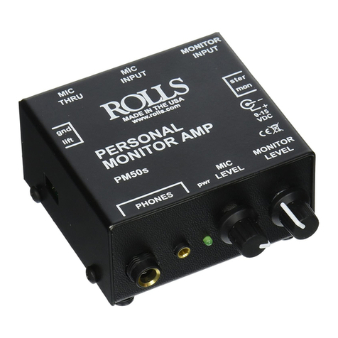
PM55 Personal Monitor Amplifier
The PM55 is an essential monitoring tool for studio or live
applications. It allows you to mix a mic signal and a monitor signal
and hear them via headphones.
• XLR Mic In & Pass Through
• Ground lift on XLR signal
• Stereo/Mono 1/4" Monitor Input
• Headphone and earphone outputs
• Battery or AC operation
• Lots of output level, it's loud.
PM55
PM55
PM55
SPECIFICATIONS
Max Input Level: -20 dB XLR, 40 dB monitor
Input Impedance: 600 Ohm Mic,
22k Ohm Monitor
Output Impedance: 10 Ohms
Gain: 15 dB 1/4", 50 dB XLR
Bandwidth: 50 - 20 kHz
S/N Ratio: 90 dB
Power: 9 - 15 VDC
Size: 3" x 2.5" x 1.25"
(7.6 x 6 x 3.2 cm)
Weight: 1 lb (.45 Kg)
INTRODUCTION
Thank you for your purchase of the PM55 Stereo Personal Monitor
Amplifier. This unit is a unique device for monitoring ones self and
program material at the same time. It has a monitor level control
and a mic level control, a mic pass-through XLR jack, earphone
and headphone output jacks, and a switchable stereo/mono 1/4"
monitor input jack.
The PM55 is designed for performers who need to monitor their
own signal, such as their vocals, with the main mix. It has become
very popular with drummers who need to mix a click track with a
monitor signal. Church choir singers love the PM55 to monitor their
voices over the musicians. And many sound technicians use the
PM55 as a quick line tester to troubleshoot audio systems.
The PM55 features all these benefits in a convenient battery-pow-
ered package.
DESCRIPTION
MIC THRU: XLR jack paralleled
(hard-wired) to the MIC INPUT
jack for pass-through to a mixer
or other input device.
lift/gnd: Header jumper for con-
necting or disconnecting the XLR
ground (pin 1) to cassis ground.
The PM55 is configured at the
factory with pin 1 connected to
ground.
MIC INPUT: XLR balanced jack
for connection to a condenser or
dynamic microphone.
MONITOR INPUT: 1/4" TRS
stereo jack for connection to a line source such as a mixer monitor/
auxiliary output, cassette player output, CD player output etc.
POWER: This button turns the PM55 on and off.
BATTERY: Compartment for 9 Volt (alkaline preferred) battery.
stereo/mono: Header jumper to configure the Monitor input for TRS
stereo or TS mono operation. The PM55 is configured at the factory
in stereo mode.
9 - 15 VDC: For connection to the Rolls PS27 AC power adapter.
PHONE OUTPUTS: One 1/4" TRS stereo headphone output, one
1/8" TRS stereo earphone output.
pwr: Indicates the PM55 is on.
MIC LEVEL: Adjusts the level of signal coming from the MIC IN-
PUT.
MONITOR LEVEL: Adjusts the level of the incoming signal from the
Monitor Input.
MIC
IN
MIC
THRU
MONITOR
IN
BATTERY
PHONES
MIC
LEVEL
MONITOR
LEVEL
PM55
PERSONAL
MONITOR AMP +9 - 15
VDC
pwr
lift gnd
ster
mon
POWER
WARRANTY
For information on the Rolls One Year Limited Warranty, and
to register this product, visit our website at www.rolls.com
SCHEMATIC
To view the PM55 schematic, visit our website at www.
rolls.com.
67 5 8 8 9 0 5 0 5 5
4
PM55 MONITOR
MADE IN USA
PHANTOM
POWER
on off
MADE IN USA
PHANTOM
POWER
on off
Rolls utilizes a way of switching phantom power ON and OFF thru a three pin jumper wire that is attached to the unit and a
external bridge clip to act as a switch for switching between two preset unit options. For example on other Rolls units it might
be for switching between phantom power on/off as illustrated above or it may be used for switching between ground/lift or
other options as denoted on the silk screening of the unit.
-To switch between options the Bridge clip can be moved from one option/side to the other just like a switch.
-To do this simply grab the bridge clip with a pair of needle nose pliers or tweezers and pull outward from the unit
disconnecting it from the pins of the unit completely.
-The middle pin is utilized in either position. In the above illustration (OFF) the middle pin is connected to the left side pin with
the bridge clip to have the phantom power OFF.
-To have the phantom power (ON) connect the middle pin and right pin together with the bridge clip as in the illustration below.
Please note that you must follow the silk screening of the unit to know what the jumper wire does and to which side is on or
off.All of our units are different, but great care is taken to insure that the silk screening is correct.
We use the bridge clip/jumper wire combination in place of switches due to there reliability. Switches break. Our system has
been in use for many years and we have never seen a single unit back with broken pins. We have seen many of our other
units back for repair for a simple broken switch.
We have found that customers like products better that do not break down in the field, and that they also do not like being
with out products that have to be sent back for repair. Knowing these facts we are committed to using this system in the future.
Rolls Bridge Clip/Jumper Wire explanation
OFF - POSITION
ON - POSITION

Other Rolls Amplifier manuals

Rolls DU30b User manual

Rolls

Rolls DU30b User manual

Rolls RA63B User manual

Rolls

Rolls RA63B User manual

Rolls RA200 User manual

Rolls

Rolls RA200 User manual

Rolls RA235 User manual

Rolls

Rolls RA235 User manual

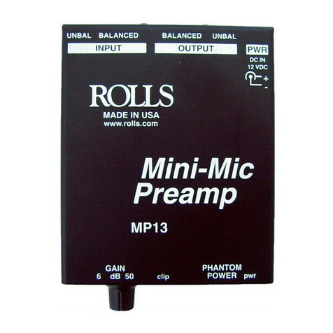
Rolls MP13 User manual

Rolls

Rolls MP13 User manual

Rolls RA170 User manual

Rolls

Rolls RA170 User manual

Rolls RA2100b User manual

Rolls

Rolls RA2100b User manual

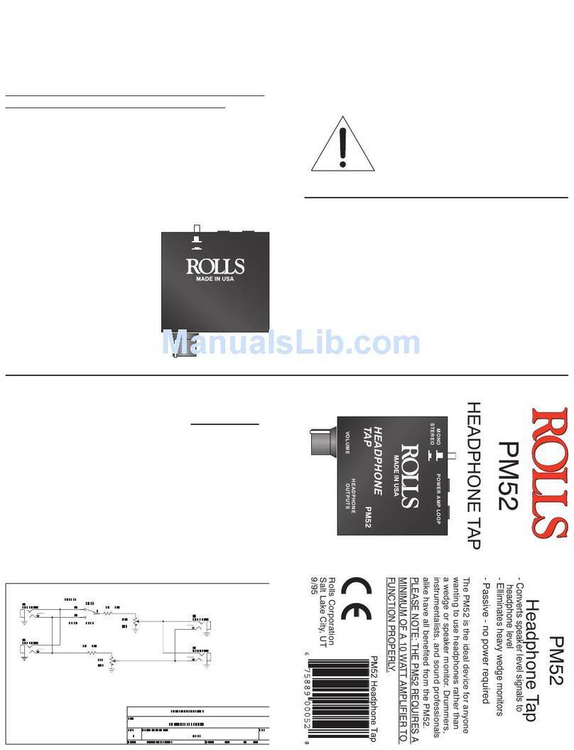
Rolls PM52 User manual

Rolls

Rolls PM52 User manual

Rolls RA2200 - SCHEMA User manual

Rolls

Rolls RA2200 - SCHEMA User manual

Rolls MA251 User manual

Rolls

Rolls MA251 User manual

Rolls MA2355 User manual

Rolls

Rolls MA2355 User manual

Rolls RA163 User manual

Rolls

Rolls RA163 User manual

Rolls RP520 User manual

Rolls

Rolls RP520 User manual

Rolls RA62c User manual

Rolls

Rolls RA62c User manual

Rolls RA235 User manual

Rolls

Rolls RA235 User manual

Rolls RA102 User manual

Rolls

Rolls RA102 User manual

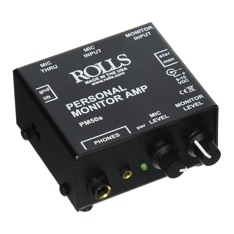
Rolls PM50s User manual

Rolls

Rolls PM50s User manual

Rolls PA71 User manual

Rolls

Rolls PA71 User manual

Rolls RA62 User manual

Rolls

Rolls RA62 User manual

Rolls MA2355 User manual

Rolls

Rolls MA2355 User manual

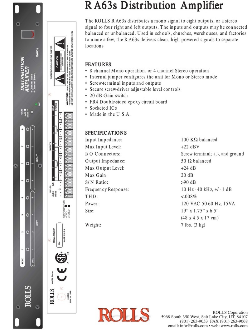
Rolls RA63s User manual

Rolls

Rolls RA63s User manual

Rolls RA63S - MANUAL 2 User manual

Rolls

Rolls RA63S - MANUAL 2 User manual

Rolls RA900 User manual

Rolls

Rolls RA900 User manual

Rolls RA900 User manual

Rolls

Rolls RA900 User manual

Popular Amplifier manuals by other brands

Krell Industries Phone Preamplifier Specification sheet

Krell Industries

Krell Industries Phone Preamplifier Specification sheet

Crown 140MPA Specifications

Crown

Crown 140MPA Specifications

Elan D1200 Installation manual and user's guide

Elan

Elan D1200 Installation manual and user's guide

ELECTROCOMPANIET PI-2 owner's manual

ELECTROCOMPANIET

ELECTROCOMPANIET PI-2 owner's manual

Ltc Audio KARAOKE-STAR4MKII user manual

Ltc Audio

Ltc Audio KARAOKE-STAR4MKII user manual

M2 Antenna Systems 2M-1K2 operating instructions

M2 Antenna Systems

M2 Antenna Systems 2M-1K2 operating instructions

SWR amplite user guide

SWR

SWR amplite user guide

thomann Harley Benton HB-160B user manual

thomann

thomann Harley Benton HB-160B user manual

Swan Song Audio Mini Phono operating instructions

Swan Song Audio

Swan Song Audio Mini Phono operating instructions

Avaya HIS user guide

Avaya

Avaya HIS user guide

RAM XTR Series Installation and operation manual

RAM

RAM XTR Series Installation and operation manual

Galaxy Audio JIB/PA50 user manual

Galaxy Audio

Galaxy Audio JIB/PA50 user manual

Kramer VM-4HDT user manual

Kramer

Kramer VM-4HDT user manual

FONESTAR FS-2481E instruction manual

FONESTAR

FONESTAR FS-2481E instruction manual

Pass Laboratories XA60.5 owner's manual

Pass Laboratories

Pass Laboratories XA60.5 owner's manual

OM POWER OM1002 instruction manual

OM POWER

OM POWER OM1002 instruction manual

Simplex Flex 4100U installation instructions

Simplex

Simplex Flex 4100U installation instructions

Cyrus aCA7.5 User instructions

Cyrus

Cyrus aCA7.5 User instructions

manuals.online logo
manuals.online logoBrands
  • About & Mission
  • Contact us
  • Privacy Policy
  • Terms and Conditions

Copyright 2025 Manuals.Online. All Rights Reserved.