4801-5181 Revision A10
RS-600 High-Temperature Oven Door Installation Manual
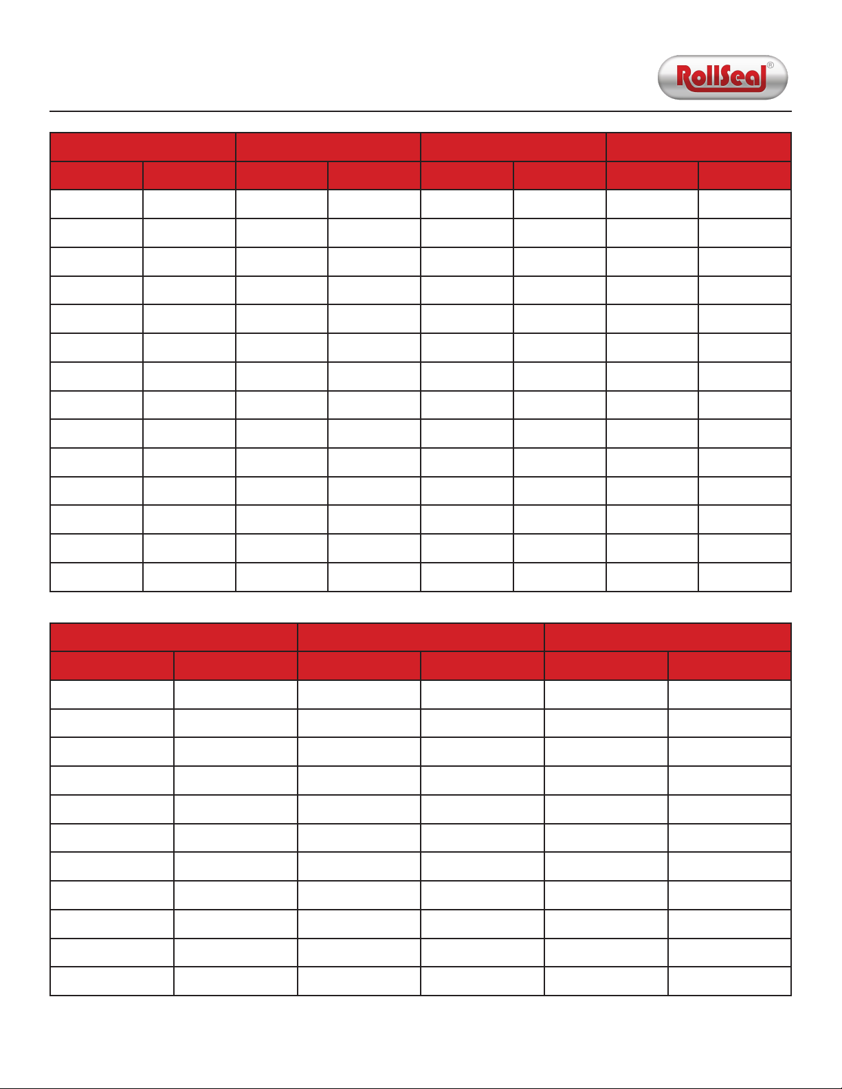
A B C D
Standard Metric Standard Metric Standard Metric Standard Metric
36" 914 mm 48" 1,219 mm 64-3/8" 1,635 mm 69" 1,753 mm
48" 1,219 mm 60" 1,524 mm 76-3/8" 1,940 mm 81" 2,057 mm
60" 1,524 mm 72" 1,829 mm 88-3/8" 2,245 mm 93" 2,362 mm
72" 1,829 mm 84" 2,134 mm 100-3/8" 2,450 mm 105" 2,667 mm
78" 1,981 mm 90" 2,286 mm 106-3/8" 2,702 mm 111" 2,819 mm
84" 2,134 mm 96" 2,438 mm 112-3/8" 2,854 mm 117" 2,872 mm
96" 2,438 mm 108" 2,743 mm 124-3/8" 3,159 mm 129" 3,277 mm
108" 2,743 mm 120" 3,048 mm 136-3/8" 3,464 mm 141" 3,581 mm
120" 3,048 mm 132" 3,353 mm 148-3/8" 3,769 mm 153" 3,886 mm
132" 3,353 mm 144" 3,658 mm 160-3/8" 4,074 mm 165" 4,191 mm
144" 3,658 mm 156" 3,962 mm 172-3/8" 4,378 mm 177" 4,496 mm
156" 3,962 mm 168" 4,267 mm 184-3/8" 4,683 mm 177" 4,496 mm
168" 4,267 mm 180" 4,572 mm 196-3/8" 4,988 mm 201" 5,105 mm
180" 4,572 mm 192" 4,877 mm 208-3/8" 5,293 mm 213" 5,410 mm
E F G
Standard Metric Standard Metric Standard Metric
72" 1,829 mm 84" 2,134 mm 107-3/4" 2,737 mm
78" 1,981 mm 90" 2,286 mm 113-3/4" 2,889 mm
84" 2,134 mm 96" 2,438 mm 119-3/4" 3,042 mm
96" 2,438 mm 108" 2,743 mm 131-3/4" 3,347 mm
108" 2,743 mm 120" 3,048 mm 143-3/4" 3,651 mm
120" 3,048 mm 132" 3,353 mm 155-3/4" 3,956 mm
132" 3,353 mm 144" 3,658 mm 167-3/4" 4,261 mm
144" 3,685 mm 156" 3,962 mm 179-3/4" 4,566 mm
156" 3,962 mm 168" 4,267 mm 191-3/4" 4,871 mm
168" 4,267 mm 180" 4,572 mm 203-3/4" 5,175 mm
180" 4,572 mm 192" 4,877 mm 215-3/4" 5,480 mm
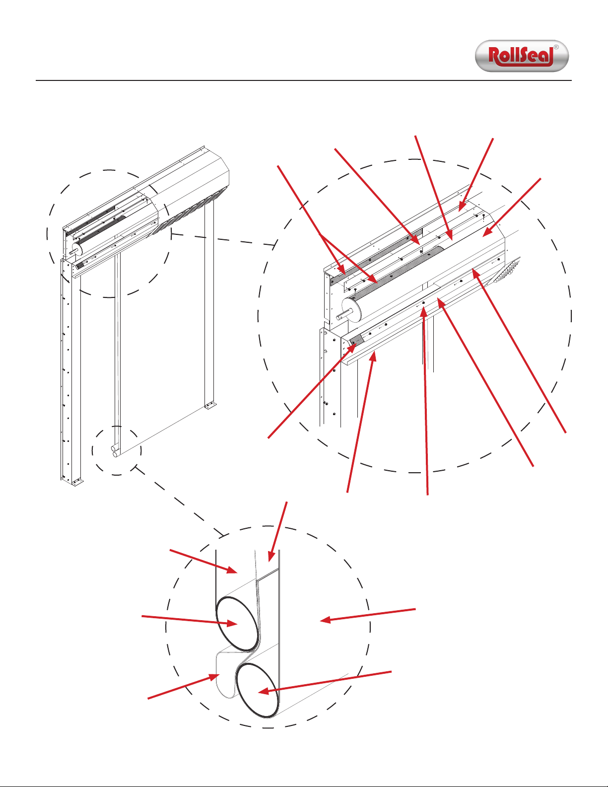
Figure 1.2: Door Width
Figure 1.3: Door Height