RollSeal RS-500M User manual

4801-9003B 8 September 20211
RS-500M/RS-600M Intrinsically Safe
Barrier Door Installation and Operation
Manual

4801-9003B 8 September 2021
2
Intrinsically Safe Barrier Door Installation and Operation Manual
Section 1: Introduction...........................................................................................................................................
Section 1.1: Definitions of Informational Headings...........................................................................................................................
Section 1.2: Scope of Manual..............................................................................................................................................................
Section 1.3: Limited Warranty.............................................................................................................................................................
Section 1.4: Component Overviews....................................................................................................................................................
Section 1.4.1: RS-500M/RS-600M ISB Door.............................................................................................................................................
Section 1.4.2: SC-325M/SC-650M ISB Smart Controller..........................................................................................................................
Section 1.5: Specifications...................................................................................................................................................................
Section 1.6: Dimensions and Installation Requirements...................................................................................................................
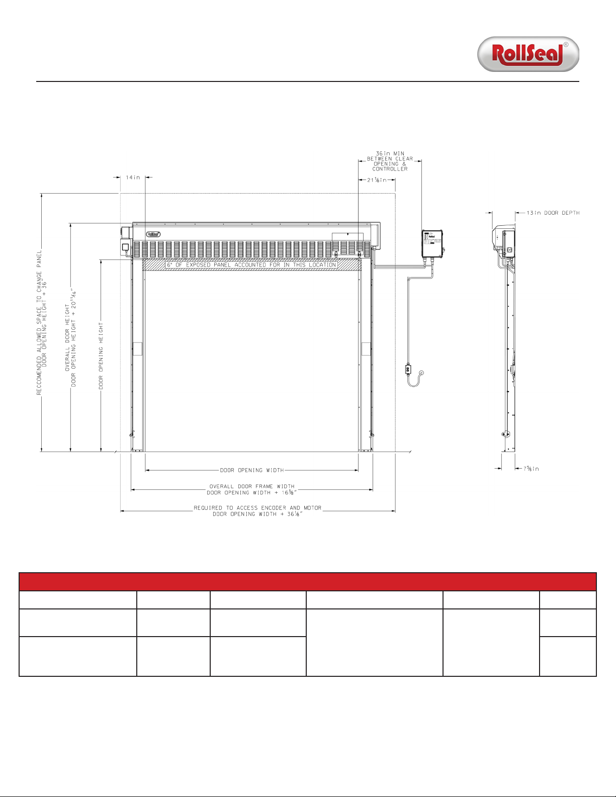
Section 1.6.1: RS-500M ISB Door.............................................................................................................................................................
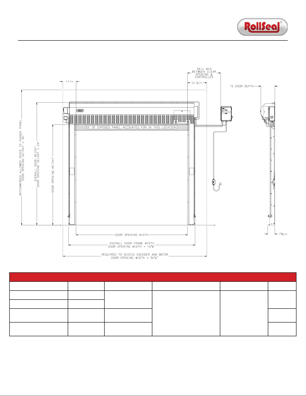
Section 1.6.2: RS-600M ISB Door.............................................................................................................................................................
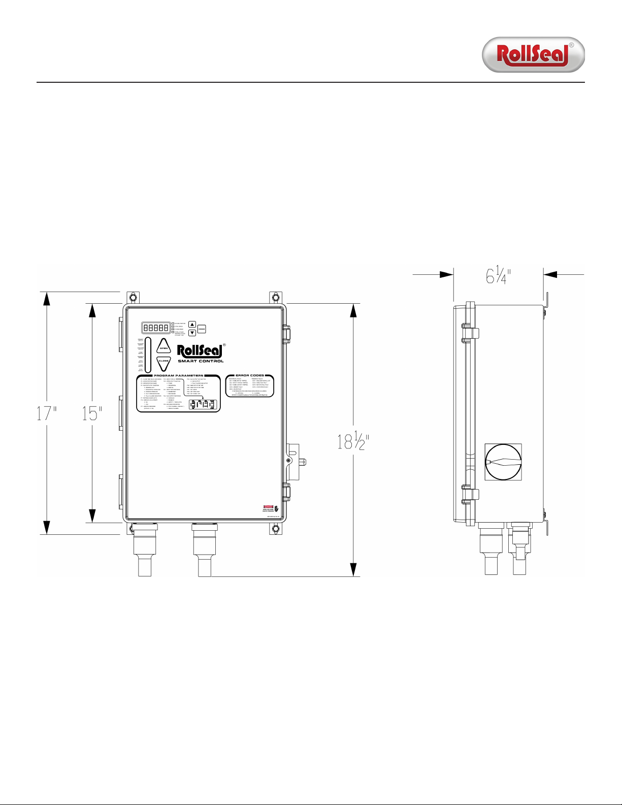
Section 1.6.3: SC-325M ISB/SC-650M ISB Smart Controller....................................................................................................................
Section 2: Installation.............................................................................................................................................
Section 2.1: Preliminary Steps............................................................................................................................................................
Section 2.2: Adjust Framing and/or Clear Opening............................................................................................................................
Section 2.3: Assemble Tracks (if Over 13' Tall)...................................................................................................................................
Section 2.4: Connect Tracks to Head Unit..........................................................................................................................................
Section 2.5: Mount Door to Clear Opening.........................................................................................................................................
Section 2.6: Mount Smart Controller..................................................................................................................................................
Section 2.7: Switches...........................................................................................................................................................................
Section 2.8: Connect Infrared Safety Beam System...........................................................................................................................
Section 2.9: Power................................................................................................................................................................................
Section 2.10: Motor Crank Handle.......................................................................................................................................................
Section 2.11: Prepare for Operation....................................................................................................................................................
Section 3: Operation...............................................................................................................................................
Section 3.1: External Switch and Smart Controller............................................................................................................................
Section 3.2: Home and Leading Edge Switch.....................................................................................................................................
Section 3.3: Infrared Safety Beam.......................................................................................................................................................
Section 3.4: Electrical Disconnect.......................................................................................................................................................
Section 3.5: Communication Between Smart Controller and Door..................................................................................................
Section 3.6: Smart Controller User Interface......................................................................................................................................
Section 3.6.1: Overview...........................................................................................................................................................................
Section 3.6.2: Display Indicator Readings..............................................................................................................................................
Section 3.7: Configuration...................................................................................................................................................................
Section 3.7.1: Program Mode..................................................................................................................................................................
Section 3.7.2: Open and Close Speeds....................................................................................................................................................
Section 3.7.3: Deceleration Range..........................................................................................................................................................
Section 3.7.4: Open and Closed Limits...................................................................................................................................................
Section 3.8: Jog Mode..........................................................................................................................................................................
Section 3.9: Door Activation Inputs.....................................................................................................................................................
Section 3.9.1: Directional Switch............................................................................................................................................................
Section 3.9.2: Manual Switch..................................................................................................................................................................
Section 3.9.3: Timed Switch....................................................................................................................................................................
Section 3.10: Relay Outputs.................................................................................................................................................................
Section 4: Maintenance...........................................................................................................................................
Section 4.1: Cleaning and Adjustment................................................................................................................................................
Section 4.1.1: Cleaning Panels and (if Present) Window.......................................................................................................................
Section 4.1.2: Adjusting Panels and Tension Pipes................................................................................................................................
Section 4.2: Component Replacement...............................................................................................................................................
Section 4.2.1: Panels...............................................................................................................................................................................
Section 4.2.2: Hook-and-Loop Seal.........................................................................................................................................................
Table of Contents
4
4
4
5
6
6
6
6
7
7
8
9
10
10
10
11
12
13
14
15
16
18
19
20
21
21
22
23
23
23
24
24
25
27
27
31
32
32
32
33
33
33
33
34
35
35
35
36
37
37
39

4801-9003B 8 September 2021
3
Intrinsically Safe Barrier Door Installation and Operation Manual
Section 5: Troubleshooting......................................................................................................................................
Section 5.1: Manual Operation Via Crank Handle...............................................................................................................................
Section 5.2: P12 Input Status Indicators.............................................................................................................................................
Section 5.3: Error Codes and Recommended Actions........................................................................................................................
Section 5.4: Drive Board Diagnostic LEDs...........................................................................................................................................
Section 5.4.1: Door Idle............................................................................................................................................................................
Section 5.4.2: Door Moving......................................................................................................................................................................
Section 5.5: Testing Brake Relay..........................................................................................................................................................
Section 6: Diagrams................................................................................................................................................
Section 6.1: Door Internal Wiring........................................................................................................................................................
Section 6.2: Smart Controller..............................................................................................................................................................
Section 6.2.1: Layout...............................................................................................................................................................................
Section 6.2.2: Internal Wiring..................................................................................................................................................................
Section 6.2.3: Interlocking Two Doors.....................................................................................................................................................
Section 6.2.4: Connecting Two-Button Switches....................................................................................................................................
Section 6.2.5: Connecting Other Switches..............................................................................................................................................
Section 6.2.6: Connecting Remote Receiver...........................................................................................................................................
Section 7: Accessories.............................................................................................................................................
Section 7.1: Passive Infrared Motion Sensor.......................................................................................................................................
Section 7.2: Wave Close-Proximity Sensor..........................................................................................................................................
Section 7.3: Large Door Motion Sensor...............................................................................................................................................
Section 7.4: One-Button Control Station............................................................................................................................................
Section 7.5: Two-Button Control Station With Key Lock....................................................................................................................
Section 7.6: Pull-Cord Switch..............................................................................................................................................................
Section 7.7: Remote Receiver and Transmitter...................................................................................................................................
Section 7.8: Auxiliary Power Supply....................................................................................................................................................
Section 8: Replacement Parts..................................................................................................................................
Section 8.1: General.............................................................................................................................................................................
Section 8.2: Smart Controller..............................................................................................................................................................
Section 9: Warnings/Avertissements.........................................................................................................................
40
40
41
42
43
43
43
44
45
45
46
46
47
48
49
50
51
52
52
52
52
52
52
52
52
52
53
53
55
56
Table of Contents (Continued)

4801-9003B 8 September 2021
4
Intrinsically Safe Barrier Door Installation and Operation Manual
Section 1.1: Definitions of Informational Headings
• DANGER: This heading indicates noncompliance with the stated information will lead to serious injury or death.
• WARNING: This heading indicates noncompliance with the stated information may lead to serious injury or death.
• CAUTION: This heading indicates noncompliance with the stated information may lead to minor or moderate injury.
• NOTICE: This heading draws attention to specific information.
Section 1.2: Scope of Manual
Section 1: Introduction
NOTICE: This document is subject to change without notice. The latest version is maintained at rollseal.net/rollseal-technicals/.
This manual describes the following aspects of the RS-500M ISB/RS-600M ISB automated door:
1. Installation of the door and its components.
2. Operation of the door and the SC-325M ISB/SC-650M ISB controller (henceforth referred to as the "Smart Controller"),
including activation methods and program configuration.
3. Maintenance, including cleaning, adjustment, and replacement of various components.
4. Troubleshooting, including diagnostic indicators and corresponding recommended actions.
5. Diagrams of the door and its components.
6. Accessory components, mostly including auxiliary activation options.

4801-9003B 8 September 2021
5
Intrinsically Safe Barrier Door Installation and Operation Manual
Section 1.3: Limited Warranty
RollSeal, a division of HH Technologies, Inc., warrants the RollSeal Door ("the Product") to be free from defects in material and/or
workmanship for a period of either (a) one year from the date of invoice or (b) 100,000 cycles, whichever comes first, provided the
Product is installed and used in strict accordance with oicial documentation. Liability is limited to the sale price of the Product
or, at RollSeal's discretion, to the replacement of the Product upon its return.
This Limited Warranty excludes any labor, equipment, transportation, and/or service expenses that may be required to remedy the
warranted defect(s); all such charges must be funded by the purchaser. Neither the Product nor any of its component parts are to
be returned for repair or replacement until they have been inspected and/or a Return Goods Authorization (RGA) number has been
issued.
Complaints are to be directed first to the authorized distributor who sold the Product. If satisfaction is not obtained and/or the
distributor cannot be contacted, contact the Warrantor listed below, directed to the attention of "Customer Service Manager".
This Limited Warranty is void if (a) the Product and/or any of its component parts are found to have been misused, abused, or
otherwise tampered with by unqualified personnel; (b) any of the Product's component parts have been replaced by anything
other than authorized RollSeal replacement parts; (c) the Product has been modified in any way other than oicially sanctioned
upgrades made by qualified personnel using authorized RollSeal accessories; (d) the Product has not been appropriately
registered by its original purchaser; and/or (e) the customer cannot provide proof of purchase indicating them to be the Product's
original owner.
This Limited Warranty is made solely to the original purchaser of the Product. It cannot be transferred.
This Limited Warranty is in lieu of any and all other representations and/or warranties, expressed or implied, including any implied
warranty of merchantability and/or fitness for a particular purpose. The remedy set forth by this Limited Warranty shall be the
exclusive remedy available to any entity. No entity has the authority to bind RollSeal to any representation or warranty other
than this Limited Warranty. RollSeal shall not be liable for any damages or losses resulting from any application of the Product or
caused by any defect, failure, or malfunction of the Product.
This Limited Warranty gives you specific legal rights. You may have additional rights, as some areas do not allow the exclusion or
limitation of incidental or consequential damages. The above limitation or exclusion may therefore not apply to you.
Warrantor: HH Technologies (d.b.a. RollSeal)
Address: 1733 County Road 68; Bremen, AL 35033
Phone: 256-287-7000
Email: customerservic[email protected]

4801-9003B 8 September 2021
6
Intrinsically Safe Barrier Door Installation and Operation Manual
Specification RS-500M ISB RS-600M ISB
Smart Controller Part Number Varies 6607-8303; 6607-8304
Smart Controller Model SC-325M ISB SC-650M ISB
Power Supply 115VAC; 50/60 Hz; Single-Phase (Max 8' W)
or 230VAC; 50/60 Hz; Single-Phase (Any Size) 230VAC; 50/60 Hz; Single-Phase
Temperature Range 32°F to 115°F (0°C to 46°C) 32°F to 115°F (0°C to 46°C)
Input 10A at 115VAC; Single-Phase
or 6A at 230VAC; Single-Phase 8A at 230VAC; Single-Phase
Operational Power 3A at 115VAC; Single-Phase
or 1.5A at 230VAC; Single-Phase 3A at 230VAC; Single-Phase
Standby Power 0.2A at 115VAC; Single-Phase
or 0.1A at 230VAC; Single-Phase 0.1A at 230VAC; Single-Phase
Section 1.4.1: RS-500M ISB/RS-600M ISB Door
The RollSeal Intrinsically Safe Barrier (ISB) automated fabric roll-up door is designed to separate diering environments. It is used
in Class I Division 2 applications, including industrial finishing. The RS-500M ISB door is manufactured up to 12' W x 12' H, and has
a maximum speed of 18" per second; the RS-600M ISB door is manufactured up to 24' W x 24' H, and has a maximum speed of 48"
per second (depending on the size).
All doors have a fabric panel that consists of three layers of industrial-grade material. A dead air space between these layers
creates unrivaled separation and insulation between the environments inside and outside the door.
Section 1.4.2: SC-325M ISB/SC-650M ISB Smart Controller
The Smart Controller is manufactured specifically for the RollSeal automated door (SC-325M ISB for the RS-500M ISB;
SC-650M ISB for the RS-600M ISB). It uses internal safety devices, in conjunction with components of the door assembly, to open
and close the door automatically. The Smart Controller can also manage the opening and closing speeds of the door, count
the number of cycles the door has performed, and provide status information for remotely monitoring the door's position.
Furthermore, the Smart Controller can incorporate several auxiliary devices to improve the operation of the door; four dimples to
help drill holes for additional inputs are located at the bottom of the enclosure.
1. Integrated sensors can detect the presence of personnel and/or machinery requiring passage through the door.
2. Integrated auxiliary lights and/or audible alarms can be used to indicate the opening or closing of the door.
3. Auxiliary inputs (sold separately) can operate the door remotely. See Section 7 for details.
Section 1.4: Component Overviews
Section 1.5: Specifications
NOTICE: See the appropriate cut sheet at rollseal.net/rollseal-technicals/ for further specifications.

4801-9003B 8 September 2021
7
Intrinsically Safe Barrier Door Installation and Operation Manual
Section 1.6: Dimensions and Installation Requirements
Installation Specifications
Door Size Personnel Equipment Tools PPE Time
Up to 6' W x 9' H 2 - Forkli
- Ladder - Standard Hand Tools
(Drill, Wrenches, Level, etc.)
- Glasses
- Gloves
- Boots
- Hard Hat
~ 4 Hours
Between 6' W and 12' W
(Any Height) 3
- Forkli
- Scissor Li
- Ladder
~ 6 Hours
Section 1.6.1: RS-500M ISB Door

4801-9003B 8 September 2021
8
Intrinsically Safe Barrier Door Installation and Operation Manual
Installation Specifications
Door Size Personnel Equipment Tools PPE Time
Up to 8’ W x 8’ H 2 Ladder
- Standard Hand Tools
(Drill, Wrenches, Level, etc.)
- Glasses
- Gloves
- Boots
- Hard Hat
~ 2 Hours
12' W x 12' H 3
16' W x 16' H 3 - Ladder
- Scissor Li ~ 4 Hours
24' W x 24' H 4 - Ladder
- 2 Scissor Lis ~ 6 Hours
Section 1.6.2: RS-600M ISB Door

4801-9003B 8 September 2021
9
Intrinsically Safe Barrier Door Installation and Operation Manual
Section 1.6.3: SC-325M ISB/SC-650M ISB Smart Controller

4801-9003B 8 September 2021
10
Intrinsically Safe Barrier Door Installation and Operation Manual
Section 2: Installation
Section 2.2: Adjust Framing and/or Clear Opening
1. Using the appropriate diagram in Section 1.6, determine the required width and height of the clear opening. If necessary,
adjust the dimensions of the mounting posts and/or framing members to suit the dimensions of the door.
2. The framing material must provide adequate support for screws. Ensure the mounting posts and/or framing members are
positioned so the screw holes in the outer flanges of the vertical tracks will align with them.
3. Ensure there is adequate space for the motor and Smart Controller.
4. Allow at least 12" (ideally 18") of clearance above the head unit.
5. Allow at least 6" of clearance on the outside of each track.
6. Ensure the top screw holes in the head unit will overlap and fit flush with the framing.
7. Ensure the screw holes in the vertical tracks align with the framing. The predrilled screw holes in the inner and outer flanges
will serve as attachment points when the assembly is mounted.
Read this manual in its entirety before beginning the procedure. Inspect the contents of the shipping crate for damaged, loose, or
missing components. If any components are damaged, loose, or missing, contact your RollSeal distributor immediately.
Section 2.1: Preliminary Steps

4801-9003B 8 September 2021
11
Intrinsically Safe Barrier Door Installation and Operation Manual
Section 2.3: Assemble Tracks (if Over 13' Tall)
Tracks taller than 13' must be spliced together as follows:
1. Arrange the top and bottom tracks as shown.
2. Slide the bottom track into the top track so they butt together on the splice bracket and the splice plate.
3. Bolt the tracks together. Ensure all bolts in the splice bracket and the splice plate are fully tightened.

4801-9003B 8 September 2021
12
Intrinsically Safe Barrier Door Installation and Operation Manual
Section 2.4: Connect Tracks to Head Unit
Each end of the head unit has a U-shaped plate that fits the corresponding track. The plate has four bolt holes (two on the outside
and two on the inside) that match the bolt holes in the tracks.
1. Arrange the head unit and both tracks on the floor, face-down in front of the clear opening.
2. Align each track with the plate at the corresponding end of the head unit.
3. Slide each track onto the outside of the plate.
4. Insert the bolts through the bolt holes, then install the nuts.

4801-9003B 8 September 2021
13
Intrinsically Safe Barrier Door Installation and Operation Manual
Section 2.5: Mount Door to Clear Opening
1. Center the door assembly in front of the clear opening. Align the bottom of each track with the corresponding framing
member or post.
2. Ensure the assembly is square and level.
3. Position all workers, forklis, etc. on each side of the assembly.
4. Lean the assembly upright against the clear opening.
5. Carefully press the flanges flush against the framing members or posts.
6. Secure the door assembly by installing the provided hex-drive rivets through the prepunched holes at the corners. For
all other prepunched holes, if mounting the assembly to metal, use the provided self-tapping screws or stitch screws. If
mounting the assembly to wood, use wood screws (not provided).
7. If installing the door for an insulated panel application without wood or metal backing, install the provided anchors on the
corners of the head unit and the top and bottom of the track flanges.
8. Drill a 1/4" hole in each of the two floor mounting holes at the bottom of the le track, then install the provided hammer-set
anchors. Repeat this step on the right track.

4801-9003B 8 September 2021
14
Intrinsically Safe Barrier Door Installation and Operation Manual
Section 2.6: Mount Smart Controller
1. Using four screws, mount the Smart Controller next to the top-right corner of the door, at least 3' from the clear opening.
2. Ensure the Smart Controller is not connected to power and the electrical disconnect next to the controller is turned o.
3. Plug the circular plastic connectors (CPCs) from the AC and DC harnesses (located at the bottom of the enclosure on the right
side of the head unit) into the receptacles on the bottom of the controller.
NOTICE: Each CPC has a key to prevent the pins from being pushed out and/or damaged if the CPC is inserted incorrectly. Ensure
the key is aligned before applying pressure. Once the pins are engaged, twist the threaded rings to lock the CPC in place.

4801-9003B 8 September 2021
15
Intrinsically Safe Barrier Door Installation and Operation Manual
Section 2.7: Switches
NOTICE: RollSeal recommends using a prewired activation switch kit. Open and close signals are wired through intrinsically safe
barriers. Other activation devices should be wired through these channels unless classified for use in the operating environment.
NOTICE: See Section 6 for switch wiring diagrams.
1. Connect the CPC from the outside switch to the Smart Controller.
2. Mount the outside switch in the desired location.
3. Drill a 1" hole through the wall.
4. Route the inside switch harness through the hole, then connect the CPC to the bottom of the outside switch.
5. Mount the inside switch in the desired location.
6. Install P-clamps on the conduit as required. Mount one near the CPC to prevent tampering.
7. Install conduit cover plates on both sides of the hole you drilled in Step 3.

4801-9003B 8 September 2021
16
Intrinsically Safe Barrier Door Installation and Operation Manual
Section 2.8: Connect Infrared Safety Beam System
The tracks house an infrared emitter and receiver. If the infrared beam is interrupted (e.g. by a person or a forkli) while closing,
the door will stop and reverse to the fully open position. See Section 3.3 for details. The emitter and receiver are set up as follows:
1. Access the electrical enclosure:
- If the motor is mounted at the top-right corner of the head unit, locate the enclosure mounted near the motor. Remove the
harness plate from the enclosure by removing the four screws holding it in place.
- If the motor is mounted on the le side of the head unit, locate the enclosure on the right side of the head unit. Remove the
cover from the enclosure by loosening the two captive screws 1/4 turn.
2. Remove the two knock-outs from the side of the enclosure (if the motor is at the top right) or the bottom of the enclosure (if
the motor is on the le) by striking them outward from the inside.
3. Remove the serrated nuts from the strain reliefs.
4. Connect the safety beam harnesses to their mates inside the enclosure. Secure the harnesses using zip ties and adhesive
mounts to prevent them from rubbing against the encoder.
5. Reinstall the harness plate or enclosure cover using the original fasteners.
6. On the le track, remove the 1/4"-20 finish nut at the height where the sensor is to be mounted (typically the second from the
floor).
7. Install the bracket from the longer harness on the stud, ensuring it is flush with the front of the track.
8. Reinstall the 1/4"-20 finish nut.
9. Route the wiring up the track to the electrical enclosure, then secure it using the provided P-clamps along the sides of the
tracks.
10. Coil the excess wiring, then secure it at the top of the door.
11. Repeat Steps 6-10 with the shorter harness on the right track.

4801-9003B 8 September 2021
17
Intrinsically Safe Barrier Door Installation and Operation Manual

4801-9003B 8 September 2021
18
Intrinsically Safe Barrier Door Installation and Operation Manual
Section 2.9: Power
NOTICE: All RollSeal doors and controllers are ordered according to specific power requirements, which are listed in Section 1.5
and on the door's serial number label. Contact RollSeal for details.
• The SC-325M ISB Smart Controller and the corresponding RS-500M ISB door can use either a 115VAC or 230VAC power supply.
However, the voltage switch is preset to 230VAC, so it must be toggled manually for 115VAC operation.
• The SC-650M ISB Smart Controller and the corresponding RS-600M ISB door typically use a 230VAC power supply. However, if
the door is up to 8' wide, it can instead use a 115VAC power supply as long as the voltage switch is toggled to 115VAC.
1. Route power to the Smart Controller, using the dimples on the bottom of the controller as a guide for drilling.
2. Route all non-RollSeal conduits and connectors.
3. Separate the high-voltage AC and low-voltage DC wiring. The switch and power wiring must be in dierent conduits.
4. Connect incoming power to the terminal block located to the le of the power disconnect.
5. Ensure all cable connections are complete and proper voltage is supplied before powering on the door.

4801-9003B 8 September 2021
19
Intrinsically Safe Barrier Door Installation and Operation Manual
The motor crank handle is used to manually operate the door in the event of power failure (see Section 5.1). It is installed as
follows:
- Insert the handle into the two pre-installed mounts on the bottom of the le track. The handle should snap into place.
Section 2.10: Motor Crank Handle

4801-9003B 8 September 2021
20
Intrinsically Safe Barrier Door Installation and Operation Manual
Perform the following steps before operating the door:
1. Apply power to the Smart Controller (see Section 2.9), then turn the disconnect to the On position.
2. Press and hold the Mode button on the Smart Controller for five seconds to engage Program Mode (see Section 3.7.1).
"P1" (Close Time Delay) will appear on the Display Indicator.
3. Verify the value of P1 (Close Time Delay) is consistent with your requirements.
4. Press the Mode button until "P20" (Open Input Function) is displayed.
5. Verify the value of P20 (Open Input Function) is consistent with your requirements.
6. Press the Mode button until "PS1" (Change Program Limits) is displayed.
7. Press the Up arrow button until "Yes" is displayed.
8. Press the Mode button again. "PS2" (Set Open Limit) will be displayed.
9. The door will proceed to the open limit, then stop. Once the door stops, adjust the open limit using the Up and Down arrow
buttons. The upper limit is generally set flush with the bottom edge of the top bar on the head unit.
10. Press the Mode button again. "PS3" (Set Closed Limit) will be displayed.
11. The door will proceed to the closed limit, then stop. Once the door stops, adjust the closed limit using the Up and Down arrow
buttons. The lower limit is normally set where the door touches the floor but the center panel is not slack.
12. Press the Mode button again. The Smart Controller will exit Program Mode.
13. Press the Open button on the outside switch. If the door is set to close automatically, it will time out and then close
automatically as long as the safety beam (see Section 3.3) is unobstructed. If the door is set to close manually, press the Close
button on the outside switch.
14. Press the Open button (and the Close button if necessary) a few times to verify the door opens and closes properly.
15. Repeat Steps 13 and 14 on the inside switch.
16. Verify the door stops and reverses to the fully open position when the safety beam is interrupted while the door closes.
17. Verify the leading edge switch (see Section 3.2) is operational.
18. Verify the door movement LEDs (if equipped) and the egress buzzer (if equipped) function properly.
19. If the door has not yet been connected to its permanent power supply, do so before the door enters regular operation.
Section 2.11: Prepare for Operation
Other manuals for RS-500M
1
This manual suits for next models
3
Table of contents
Other RollSeal Industrial Equipment manuals
Popular Industrial Equipment manuals by other brands

AL-KO
AL-KO PROFI V3000 Translation of the original operating instructions

Panasonic
Panasonic EXCX4CE quick start guide

EWC Controls
EWC Controls PRD Technical bulletin

GE
GE AKD-20 AR Installation and maintenance manual

Vestil
Vestil EM1-200 owner's manual

Graco
Graco UniDrum C59784 Instructions and parts list

Siemens
Siemens MO320 operating instructions

Heidolph
Heidolph LABOROTA 20 control automatic Series instruction manual

V-TEK
V-TEK TM-403 user guide

TDI
TDI MCL488 Series Operation & programming manual

QSA Global
QSA Global OPENVISION DX OVDX-NDT-70 Hardware manual

Siemens
Siemens 3VT94-6AC00 Series operating instructions