Rondish Nexus User manual

Rondish Company Limited
Nexus Call System
User Instructions
V1.7 (2
nd
March 2021)

NEXUS CALL SYSTEM by Rondish
P2
Contents
Contents ........................................................................................................................................................ 2
1. PRODUCT OVERVIEW ............................................................................................................................... 4
1.1 Syste Layout ................................................................................................................................. 4
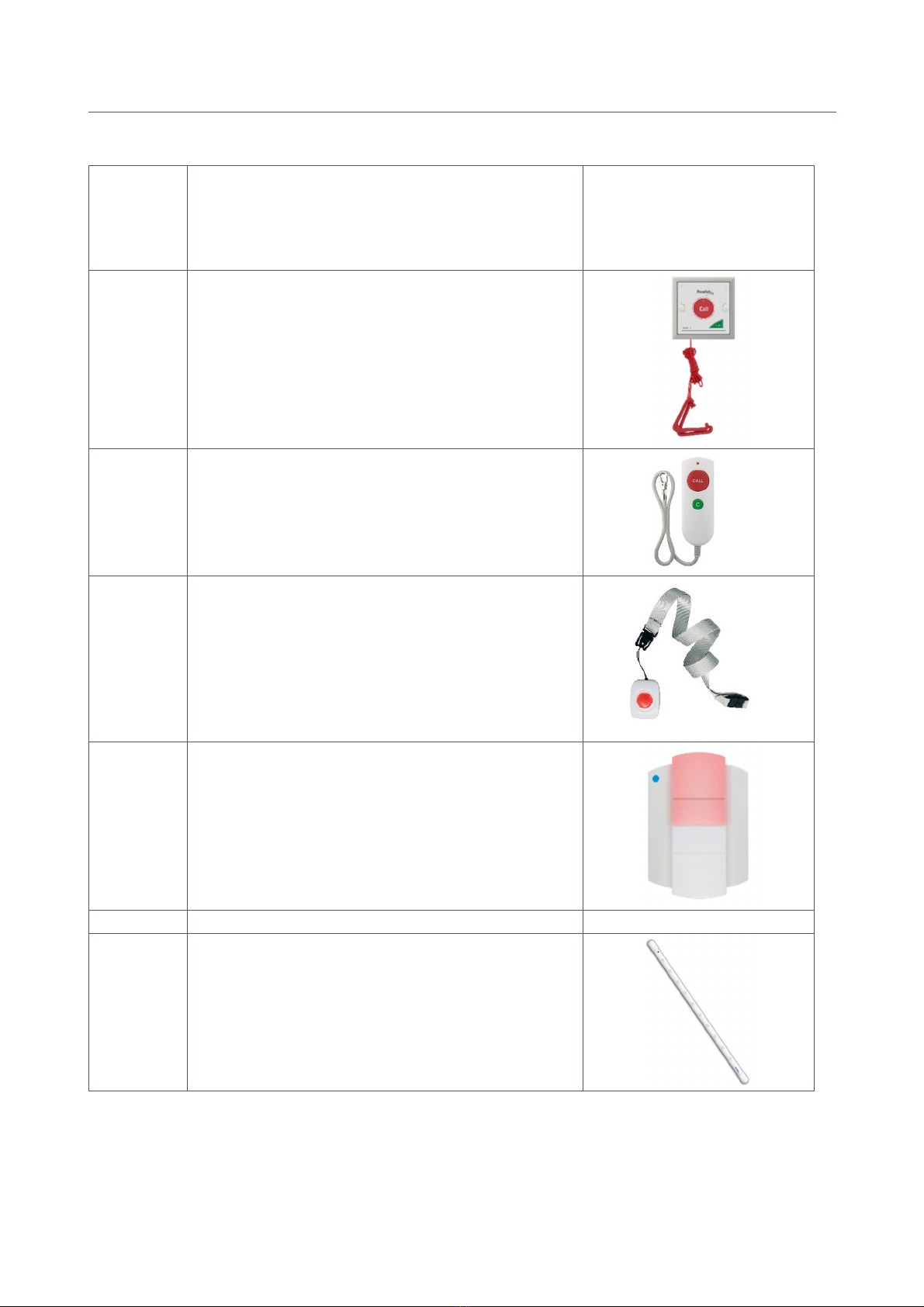
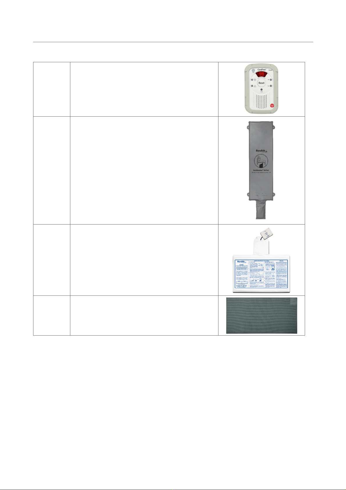
1.2 Co patible Equip ent .................................................................................................................. 6
1.3 General Operation .......................................................................................................................... 9
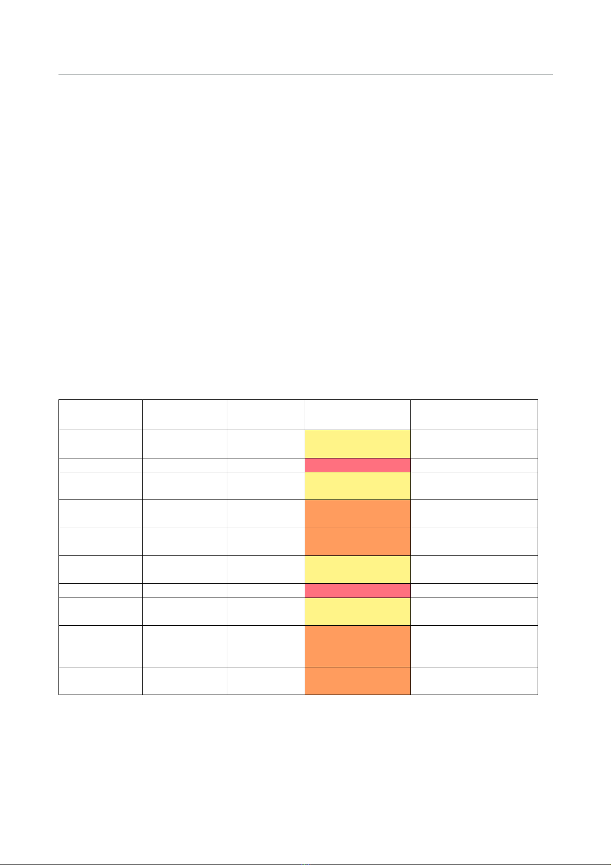
1.3.1 Nexus Behavior Table .............................................................................................................. 9
2. USER INTERFACE .................................................................................................................................... 10
2.1 Ho e Screen ................................................................................................................................. 10
2.2 Alar Screen ................................................................................................................................. 11
2.2.1 Display Details ........................................................................................................................ 11
2.2.2 Ad in Reset ........................................................................................................................... 12
2.2.3 Dongle Error ........................................................................................................................... 13
2.3 Device Manage ent .................................................................................................................... 13
2.3.1 Add New Device..................................................................................................................... 13
2.3.2 Device Location ...................................................................................................................... 15
2.3.3 Delete Device ........................................................................................................................... 16
2.4 Event Log ....................................................................................................................................... 16
2.5 Settings ............................................................................................................................................ 17
2.5.1 Change Settings ..................................................................................................................... 17
2.5.2 Backup/Restore ...................................................................................................................... 18
2.5.3 Export Log ............................................................................................................................... 18
3. INSTALLING NEXUS ................................................................................................................................ 19
3.1 Call Points ...................................................................................................................................... 19
3.2 Indication Lights ............................................................................................................................ 20
3.3 Bed Monitors ................................................................................................................................. 23
3.4 Door Monitors ............................................................................................................................... 23
3.5 Wall- ounting the Panel ............................................................................................................. 24
3.6 Maintaining Nexus ........................................................................................................................ 24
3.7 Updating Nexus ............................................................................................................................ 25

NEXUS CALL SYSTEM by Rondish
P3
4. TROUBLES OOTING .............................................................................................................................. 26
5. FCC & CE warning statements………………………………………………………………………………………………….…26-27

NEXUS CALL SYSTEM by Rondish
P4
1.
PRODUCT OVERVIEW
Nexus is a wireless nurse call syste designed for ease of progra ing, installation and use.
This allows rapid deploy ent of a low-cost call syste during influenza season when hospital
resources are stretched, or per anent installation for a long-ter care facility or hospital ward
looking for a reliable call solution.
Nexus works using a 10” Android tablet for the display – the tablet co es with a protective folio
for place ent on a desk, or can be wall- ounted with the use of an optional bracket.
Alternately, a TV Box running Nexus can be connected to a larger co puter onitor for a ore
visible display.
Up to three calls can be displayed on the screen, with higher priority calls auto atically oved
to the top of the alar display. Alar priority levels are E ergency, Bath, and standard Call. If
ore than three calls happen to be active at the sa e ti e, Nexus will display the three highest
priority events, and additional calls will display as the higher priority events are reset. All events
are logged with a record of event location, call type, ti e of trigger and duration before reset.
Indication lights placed throughout the ward or building show if there is an active call in the
area. Each light has an internal buzzer with adjustable volu e, and can repeat the signal to the
display panel to greatly extend range and i prove the reliability of wireless coverage.
1.1 Syste Layout

NEXUS CALL SYSTEM by Rondish
P5

NEXUS CALL SYSTEM by Rondish
P6
1.2 Co patible Equip ent
Model
Description
Image
NDP
-
11
10” Android Tablet with dongle (shown)
•Touch screen user interface
•Call, Bath, and E ergency priority levels
•Custo izable displays
•Event log with location, call type and response
ti e
•Includes folio for use on desktop
•US, EU, and UK power plugs included
DON
-
20
Receiver dongle for s aller areas (433MHz)
DON
-
30
Receiver dongle for large areas (LoRa)
MBKT
-
01
Wall- ount bracket for NDP-11
•Durable acrylic design
•Includes ounting screws
•Available in black or white
TVB
-
11
TV Box for corridor displays
•Allows Nexus software to run on a standard
co puter onitor
•Connect with paging receiver for a large
corridor display
GP2009TR
Paging trans itter
•Signals to re ote displays
•Signals to data pagers
•Allows wards to transfer or escalate calls to
different areas
WCP
-
11C
Bedhead call/reset point (shown)
•Call and reset buttons
•Double press sends E ergency call
•RJ10 input for NEC-12 handset (shown)
•Handset re ove alert
•Includes ounting screws
•Replaceable CR2477 lithiu batteries
•
Low battery indication
DON
-
3
0
NDP
-
1
1
NEC-12
WCP
-
11C

NEXUS CALL SYSTEM by Rondish
P7
NEC
-
12
Patient handset
•Call button for patient access fro the bed
•RJ10 plug connects with WCP-11C
•USB break connection
•
Includes wall- ount bracket and screws
WCP
-
11
Waterproof call/reset point
•Call and reset buttons
•Pull cord with dual triangles
•Includes ounting screws
•Replaceable CR2477 lithiu batteries
•Low battery alert
•
Rated IP65
NEC
-
05
Wireless patient handset
•Call and reset buttons
•Includes wall- ount bracket and screws
•Uses 2 x AAA alkaline batteries
•
Low battery alert
TXP
-
11
Patient lanyard with an-down alert
•Mobile call button for active residents
•Anti-ligature point
•Man-down alert in case of falls
•Uses CR2477 lithiu battery
•Low battery alert
•Rated IP65
ILB
-
2
1
Indication light with Signal Bu per
•Dual-color LED light – shows RED for nor al
call devices or WHITE for bath units
•Call forward function to extend range
•Includes wall- ount bracket and screws
•Uses 6 x C-type alkaline batteries
•
Low battery alert
DMS
-
0
2
Door Sensor
•Triggers audible and visual alert when an at-
risk patient approaches a protected doorway
•Configurable with door lock to restrict access
•Allows caregivers to escort patients

NEXUS CALL SYSTEM by Rondish
P8
NGM
-
21
Bed onitor
•Roo controller for integrated falls
anage ent syste
•Pause & Reset alar s
•Works with bed/chair/floor sensor ats
•Uses 3 x AA alkaline batteries
•Low battery alert
WMBP
-
20
CCP-01
CMAT-02
Sensorpads
•Triggers alar fro patient bed or chair exit.
Floor ats trigger when stepped upon
•Paired with NGM-21 onitor
•Durable and long-lasting
CCP
-
01
CMAT
-
02

NEXUS CALL SYSTEM by Rondish
P9
1.3 General Operation
Nexus follows generally accepted principles of a nurse call syste as described in the UL and
HTM-08 standards. Patient calls should be reset at location by the nurse or caregiver as soon as
can reasonably be achieved.
•Pressing a Call button on the bedhead unit triggers a Call
•Double pressing a wall- ount bedhead triggers an E ergency call
•Pressing Call on a bathroo unit triggers a Bath alar
•Pressing Reset will cancel the alar
•The RED seg ent of the indication light indicates a Call is active
•The WHITE seg ent of the indication light indicates a Bath alert is active
1.3.1 Nexus Behavior Table
The table below su arizes how Nexus interprets and displays signals fro various devices:
Device
Alarm
Trigger
Alarm Type
Display/Sound
Cancel y…
WCP-11C Single press Call Yellow, 10s beep
intervals
Reset on WCP-11C
WCP-11C Double press E ergency Red, Rapid beeping Reset on WCP-11C
NEC-12 Press button Call Yellow, 10s beep
intervals
Reset on WCP-11C
WCP-11 Press button Bath A ber, 4s beep
intervals
Reset on WCP-11
WCP-11 Pull cord Bath A ber, 4s beep
intervals
Reset on WCP-11
TXP-11 Press button Call Yellow, 10s beep
intervals
Magnetic fob on TXP-11
TXP-11 Patient fall E ergency Red, Rapid beeping Magnetic fob on TXP-11
NEC-05 Press button Call Yellow, 10s beep
intervals
“C” button on NEC-05
DMS-02 Door exit Door A ber, 4s beep
intervals
Magnetic fob on DMS-02
Press TXR-02 button
Press TTEST-01 button
NGM-21 Bed/Chair exit Bed exit/
Chair exit
A ber, 4s beep
intervals
Reset on NGM-21 or
Pad return

NEXUS CALL SYSTEM by Rondish
P10
Icons at show the Nexus screens
The organization na e can be
configured in Settings (Section 2.5)
Date and ti e will auto atically atch
your device
Software Version
Troubleshooting -
Tapping the icon
brings up a QR Code
Scan using a s artphone ca era
to download a FAQ docu ent
2. USER INTERFACE
Nexus was designed with a strea lined user interface for ease of use. The app is navigated
si ilar to how you use a s artphone, using taps and swipes for general option. A virtual
keyboard will pop up when entering text or an access PIN is required.
A co pany na e can be configured to display on the ho e screen, and alar displays are fully
custo izable according to user preferences. Nexus prioritizes alar s in three levels of
i portance, and there is a built-in record of events to aid anage ent if there is an adverse
event or response ti es are tracked over ti e.
2.1 Ho e Screen
This is the default view of the application, and Nexus will return to this screen after alar s have
been reset.

NEXUS CALL SYSTEM by Rondish
P11
2.2 Alar Screen
The alar screen will pop up when any event requires a response. If you tap on this icon when
no alar s are present, the screen will be greyed out, and auto atically return to the Ho e tab
after several seconds. Up to three alar s can be displayed on the screen at once, however
additional active alar s are indicated by the red arrow below and can be viewed by scrolling
down the screen.
Alar s are ordered top to botto by priority, with older alar s listed first.
2.2.1 Display Details
Includes ti e of the event with priority level, location, and type of alar . When all alar s have
been reset, Nexus will auto atically revert to the Ho e Screen after several seconds.
Color and – this indicates the alar priority, with a ti e sta p shown on the left side
•E ergency – RED band, rapid beeping
•Bathroo – AMBER band, 4s beep interval
•Standard Call – YELLOW band, 10s beep interval
Location 1 – this is typically a roo or ward nu ber, though is fully custo izable
Location 2 – this is typically a bed or bathroo nu ber, though it can be left blank
Call Types & Priority
E ergency
Priority 1
Emergency alarms display in RED, and
will automatically be moved to the top o
the queue.
Bath alarms display in AMBER, and have
higher priority than a standard call.
Normal Calls display in YELLOW, and will
be prioritized according to the irst call
received.
Double arrow acing downward indicates
additional calls are active

NEXUS CALL SYSTEM by Rondish
P12
Man-down
Priority 1
Bath
Priority 2
Monitor*
Priority 2
Bed
Priority 2
Chair
Priority 2
Sensor
Priority 2
Door
Priority 2
Pendant
Priority 3
Call point
Priority 3
Cord re oved
Priority 3
AC lost
Priority 3
Low battery
Priority 4
* A bed onitor displays when pairing the device to Nexus. During an alar Nexus will display
either a bed, chair, or floor type alar (refer to Section 2.3.1 for details)
2.2.2 Ad in Reset
There ay be ti es when an event needs to be cleared fro the central display panel. This can
be achieved by a long-press on the event and entering the Ad in PIN that has been assigned
for the syste .

NEXUS CALL SYSTEM by Rondish
P13
2.2.3 Dongle Error
An error essage will display if the receiver dongle is re oved or loses connection while Nexus
is active. Your syste cannot function without this receiver connected, so Nexus will pro pt
you to resolve this before any further action can be taken.
2.3 Device Manage ent
This tab is where you add/delete devices fro Nexus, and define how each should display when
an alar is triggered. Entering this tab requires inputting a 6-digit Ad in PIN to access. If you
have not set a PIN the default is 123456.
2.3.1 Add New Device
Fro this screen, triggering a device can have two effects:

NEXUS CALL SYSTEM by Rondish
P14
The device ID will show on the grey
color band at the top. This will
typically atch the serial label on the
back of a call point.
The device type icon will display on
the right
If Nexus does not already have this device in e ory it will create a new entry with the 6-digit
device ID, device type and notification that new hardware has been detected.
If Nexus already recognizes a device that is triggered while in Device Manage ent, it will exit to
the Alar Screen as if a patient has nor ally triggered an alar . This ensures the call syste
continues to function if a patient needs help.
Bed Alarms
To add a onitor for a bed or chair sensorpad, first configure a CordFree bed onitor (NGM-21)
to work with Nexus. It should be set to T1 and F1 for ost convenient operation (refer to
Section 3.3 for ore details). Fro the Device Manage ent tab, press Reset on the onitor to
pair it with Nexus, and then assign display details. It should appear si ilar to below:
Once the onitor has been paired, you can then synch either a bed or chair sensorpad with the
onitor, and Nexus will display the selected location with either a Bed or Chair type alar when
the patient exits.

NEXUS CALL SYSTEM by Rondish
P15
Device ID – usually atches the serial
label on back of call point.
Device Type icon
Location 1 – to be configured by user
( ust be defined)
Location 2 – to be configured by user
(optional)
Door Alarms
Fro the Device Manage ent tab, trigger a reset signal on the door sensor to add the device
into Nexus e ory. This can be done by applying a agnet over the blue dot on the side of
the door sensor. (refer to Section 3.4 for additional details)
2.3.2 Device Location
Tapping on the Device you have just added will bring up the screen below, pro pting you to
enter a Pri ary and Secondary location. The text you enter here will display when this device is
in alar state.
Click OK to confir the location details, and these will now display on the Device Manage ent
screen.
If you want to change how the alar is displayed you can just tap on the entry again to ake
a end ents.

NEXUS CALL SYSTEM by Rondish
P16
Event Types
•Call
•E ergency
•Presence
•Visit
•Low battery
•Signal lost
•Acknowledge
2.3.3 Delete Device
If you need to re ove so ething fro e ory, swipe left over the device.
Nexus will pro pt you to confir or cancel the device re oval
2.4 Event Log
The Event Log will show the location, event type, ti e of initiation and duration of all events
fro the previous 24 hours. Alar s prior to the previous 24 hours will be stored in a data file
that can be accessed by exporting and opening using Excel, or the co plete log can be
accessed by tapping the screen seven ti es.
Your response ti e is logged as the duration between an alar triggering and being reset.
Refer to Section 2.5.2 for instruction on how to export the data log.

NEXUS CALL SYSTEM by Rondish
P17
Co pany Na e – displays on Ho e
Screen
Ad in PIN – used to access Device
Manage ent and Settings
Network Settings – used if syste
repeaters are connected (Section 2.5.4)
•Network ID
•Channel
•Gateway ID
Update – akes changes take effect
2.5 Settings
The Settings tab is where you will set the default na e to display on the Ho e screen, change
the Ad in PIN, or export the data log. Pressing this tab requires inputting a 6-digit Ad in PIN
to access. If using Nexus for the first ti e the default code is 123456
2.5.1 Change Settings
This will allow you to add a co pany na e to display on the Ho e Screen or update the Ad in
PIN. Press the Update button to ake any changes take effect.

NEXUS CALL SYSTEM by Rondish
P18
2.5.2 Backup/Restore
After progra ing your syste , the settings and Event log can be saved on a USB drive. This
allows the progra ing to be restored on a second panel if the pri ary unit goes down. Nexus
will re ind you periodically to back-up the syste .
2.5.3 Export Log
This will allow you to transfer the Event Log to a CSV file that is openable using MS Excel. Insert
a USB storage device and tap the Export Log button.
Nexus will pro pt you to confir the data export. After inserting the USB drive into a PC, the
file will be stored in Android/data/Nexus/events_date.

NEXUS CALL SYSTEM by Rondish
P19
3. INSTALLING NEXUS
Nexus has been designed for a straightforward installation process that ini izes the ti e your
technician will spend on site. Following these steps will have your syste up and running in just
a few hours:
1. Switch on the tablet or control box and connect the receiver dongle – the application will
auto atically open to a splash screen displaying the version of Nexus installed on this
device
2. Change PIN and enter na e of organization (optional) in the Settings
3. Pair devices with Nexus and define how each should display during a call – refer to
Section 2.3 for details of adding and rena ing devices.
4. Pair devices with indication lights to extend wireless coverage (optional)
5. Mount indication lights (if used), call buttons and brackets for patient handsets
6. Mount display panel on a wall (wall ount bracket is optional)
7. Test all of the call points three ti es (call & reset) to ensure that signals are reliably
received by the panel. Refer to the Event Log to confir that each signal was received.
Dongle Status
•No LED – not connected properly
•Red LED – successfully connected
•Green LED – when receiving data
3.1 Call Points
Nexus call points have ini al progra ing and installation required for a functional call
syste . Follow the steps below to configure call points:
Step 0: Insert Batteries – Nexus call points co e with batteries pre-
installed. You will need to change these periodically based on usage. The
exception is the NEC-05 handset, which uses 2 x AAA alkaline cells.
Step 1: Add to Nexus – Refer to Section 2.3 for how to pair and rena e a
call point

NEXUS CALL SYSTEM by Rondish
P20
Step 2: Mounting – Use the call point to ark the position of the screw
holes on the wall. Drill guide holes before screwing the call point into place
Step 3: Connect Handsets – A si ilar process can be followed for the
handset ounting brackets
3.2 Indication Lights
Corridor lights provide a visual indication when a call is active in the area, have a buzzer with
adjustable volu e for audible indication, and will expand the wireless range of Nexus. Follow
the below steps to configure lights with your Nexus syste .
Step 1: Power the light – Insert 6 x C-type alkaline batteries into the ILB-
21. A lead is also provided to connect with a 12V power source if the alar
will be frequently used as a call light with ultiple calls a day. In this case
batteries ay only last weeks or onths, so connecting to a DC supply is
reco ended.
When used as a bathroo light with infrequent calls (e.g. 1 inute per day)
the batteries can last up to 1 year. Note: Standby battery life (no alar s) is
ore than 2 years.
Step 2: Select settings – Re ove front lens using a 2 flat-head
screwdriver and select light settings. The dip switches control whether the
ILB-11 will forward alar s to a central o nitor unit or as a night light. The
buzzer has axi u volu e pf 108dB, and can be silenced
Switch 1 – far left: Call Forward (On/Off)
•Controls whether alar s fro paired devices are forwarded
Switch 2 – left center: Signal B mp (On/Off)
•Controls whether signals fro devices that are not paired with this
light are forwarded. This setting allows use of obile devices such
as bed onitors or patient pendants that ove between roo s
Switch 3 – right center: Gro p Reset (On/Off)
Alternate Flashing
Group Reset
Signal Bu p
Call Forward
Volu e
Table of contents
Other Rondish Security System manuals