Ronix RMD-AH08 User manual

Real time Recording &
Full HD AHD2.0 DVR
Operating Instruction
Before installing and using this product,
please read the instruction fully and keep it handy for later use.
Preliminary
1080P


1. Safety Precaution
03
Real Time Recording & Full HD Display
CAUTION: TO REDUCE THE RISK OF ELECTRIC SHOCK,
DO NOT REMOVE COVER (OR BACK).
NO USER SERVICEABLE PARTS INSIDE.
REFER SERVICINGTO QUALIFIED SERVICE PERSONNEL.
To prevent fire or shock hazard, do not expose the device to rain or moisture.
To prevent electric shocks and risk of fire hazards, do NOT use other than specific power source.
The symbol is intended to alert the user to the presence of important operating and
maintenance(servicing) instructions in the literature accompanying the unit.
The symbol is intended to alert the user to the presence of uninsulated "dangerous voltage"
within the product's enclosure that may be of sufficient magnitude to constitute a risk of
electric shock to persons.
Warning :
This equipment has been tested and found to comply with the limits for a Class A digital device, pursuant
to part 15 of the FCC Rules. These limits are designed to provide reasonable protection against harmful
interference when the equipment is operated in a commercial environment. This equipment generates,
uses, and can radiate radio frequency energy and, if not installed and used in accordance with the
instruction manual, may cause harmful interference to radio communications.
Operation of this equipment in a residential area is likely to cause harmful interference in which case the
user will be required to correct the interference at his own expense.
Caution :
Any changes or modifications in construction of this device which are not expressly approved by the
party responsible for compliance could void the user's authority to operate the equipment.
Mains power quality should be that of a typical commercial environment. If the user of the model requires
continued operation during power mains interruptions, it is recommended that the model be powered
from an uninterruptible power supply (UPS) or a battery.
Notice :
• The image used in this instruction manual are processed to help comprehension and may differ from
actual video of the camera.
• Avoid installing areas where has shock or vibration which results in the problems.
• Pay attention to safety when laying the connection cable and observe that the cable is not subjected
to heavy loads, kinks or damage and no moisture can get in.
• Never open the device such as boards or lens.
• The warranty becomes void if repairs are undertaken by unauthorized persons.
• Maintenance and repair have to be carried out only by authorized service centers.
• Use only a mild detergent to clean the housing.
• The DVR should never be operated beyond the technical specifications.
• This can lead to destruction.
• The DVR should never be operated in water.

2. Table of Contents
04
Real Time Recording & Full HD Display
. . . . . . . . . . . . . . . . . . . . . . . . . . . . . . . . . . . . . . . . . . . . . . . . . . 10
. . . . . . . . . . . . . . . . . . . . . . . . . . . . . . . . . . . . . . . . . . . . . . . . . . . 10
. . . . . . . . . . . . . . . . . . . . . . . . . . . . . . . . . . . . . . . . . . . . . . . . . . . . . . . . . . . . . 11
. . . . . . . . . . . . . . . . . . . . . . . . . . . . . . . . . . . . . . . . . . . . . . . . . . . . . . . . . . . . 12
. . . . . . . . . . . . . . . . . . . . . . . . . . . . . . . . . . . . . . . . . . . . . . . . . . . . . . . . . . 13
. . . . . . . . . . . . . . . . . . . . . . . . . . . . . . . . . . . . . . . . . . . . . . . . . . . . . . . . . . . . 14
. . . . . . . . . . . . . . . . . . . . . . . . . . . . . . . . . . . . . . . . . . . . . . . . . . 14
. . . . . . . . . . . . . . . . . . . . . . . . . . . . . . . . . . . . . . . . . . . . . . . . . . . . . . . . . . . 18
. . . . . . . . . . . . . . . . . . . . . . . . . . . . . . . . . . . . . . . . . . . . . . . . . . . . . . . . . . . 21
. . . . . . . . . . . . . . . . . . . . . . . . . . . . . . . . . . . . . . . . . . . . . . . . . . . . . . . . . . . . 27
. . . . . . . . . . . . . . . . . . . . . . . . . . . . . . . . . . . . . . . . . . . . . . . . . . . . . 29
. . . . . . . . . . . . . . . . . . . . . . . . . . . . . . . . . . . . . . . . . . . . . . . . . . . . . . . . . . . . . 31
. . . . . . . . . . . . . . . . . . . . . . . . . . . . . . . . . . . . . . . . . . . . . . . . . . . . . . . . . . . 35
. . . . . . . . . . . . . . . . . . . . . . . . . . . . . . . . . . . . . . . . . . . . . . . . . . . . . . . . . . . 36
. . . . . . . . . . . . . . . . . . . . . . . . . . . . . . . . . . . . . . . . . . . . . . . . . . . . . . . . . 39
. . . . . . . . . . . . . . . . . . . . . . . . . . . . . . . . . . . . . . . . . . . . . . . . . . . . . . . . . . 40
. . . . . . . . . . . . . . . . . . . . . . . . . . . . . . . . . . . . . . . . . . . . . . . . 40
. . . . . . . . . . . . . . . . . . . . . . . . . . . . . . . . . . . . . . . . . . . . . . . . 40
. . . . . . . . . . . . . . . . . . . . . . . . . . . . . . . . . . . . . . . . . . . . . . . . . . . . . . . . . . . 41
. . . . . . . . . . . . . . . . . . . . . . . . . . . . . . . . . . . . . . . . . . . . . . . . . . . . . . . . . . 50
. . . . . . . . . . . . . . . . . . . . . . . . . . . . . . . . . . . . . . . . . . . . . . . . 50
. . . . . . . . . . . . . . . . . . . . . . . . . . . . . . . . . . . . . . . . . . . . . . . . . . . . . . . . . . . 50
. . . . . . . . . . . . . . . . . . . . . . . . . . . . . . . . . . . . . . . . . . . . . . . . . . . . . . . . . . 55
. . . . . . . . . . . . . . . . . . . . . . . . . . . . . . . . . . . . . . . . . . . . . . . . . . . . . . . . 55
. . . . . . . . . . . . . . . . . . . . . . . . . . . . . . . . . . . . . . . . . . . . . . . . . . . . . . . . . 55
1. Safety Precautions
. . . . . . . . . . . . . . . . . . . . . . . . . . . . . . . . . . . . . . . . . 03
2. Table of Contents
. . . . . . . . . . . . . . . . . . . . . . . . . . . . . . . . . . . . . . . . . . 04
3. Features
. . . . . . . . . . . . . . . . . . . . . . . . . . . . . . . . . . . . . . . . . . . . . . . . . . 05
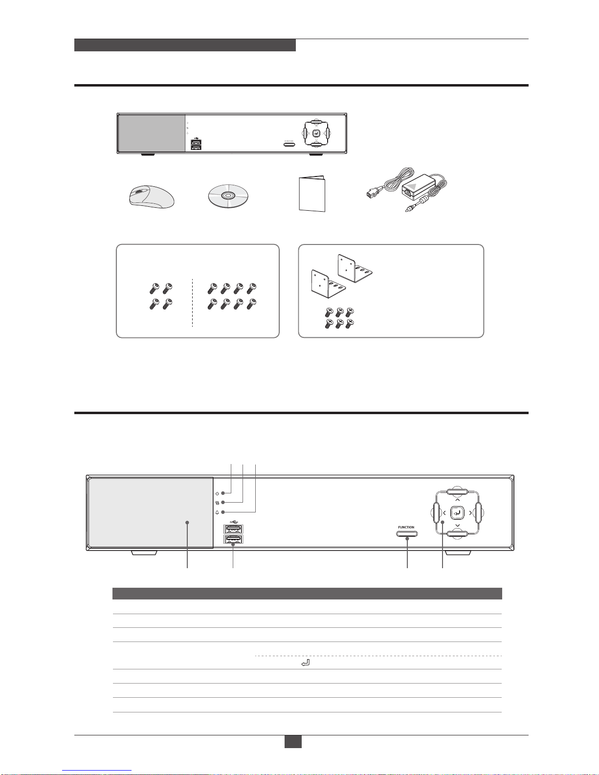
4. Components
. . . . . . . . . . . . . . . . . . . . . . . . . . . . . . . . . . . . . . . . . . . . . . 06
5. Name and Function of Each Part
. . . . . . . . . . . . . . . . . . . . . . . . . . . . 06
6. Specifications
. . . . . . . . . . . . . . . . . . . . . . . . . . . . . . . . . . . . . . . . . . . . . 09
7-1. Product Installation
7-2. System Operating
7-3. Setup
7-4. Search
7-5. Playback
7-6. Backup
7-7. Network Monitoring
7. Operation
. . . . . . . . . . . . . . . . . . . . . . . . . . . . . . . . . . . . . . . . . . . . . . . . . 10
8-1. System
8-2. Network
8-3. Record
8-4. Hard disk(HDD)
8-5. Event
8-6. Account
8-7. Camera
8-8. Information
8. Setup menu
. . . . . . . . . . . . . . . . . . . . . . . . . . . . . . . . . . . . . . . . . . . . . . . 15
9-1. Summary
9-2. System Requirements
9-3. Installing the Program
9-4. Program
9. CMS
. . . . . . . . . . . . . . . . . . . . . . . . . . . . . . . . . . . . . . . . . . . . . . . . . . . . . . 40
10-1. Summary
10-2. Installing the Program
10-3. Program
10. Mobile
. . . . . . . . . . . . . . . . . . . . . . . . . . . . . . . . . . . . . . . . . . . . . . . . . . . . 50
11-1. Summary
11-2. Preparation
11-3. Execution
11. Appendix-Emergency Recovery
. . . . . . . . . . . . . . . . . . . . . . . . . . . 55

3. Features
05
Real Time Recording & Full HD Display
• 4ch/8ch/16ch Stand-alone HD Display Real time DVRs (1080p)
• Camera menu control through Up-The-Coax.(UTC) communication.
• 4ch/8ch Stand-alone AHD2.0 FHD DVRs (1080p)
• 4ch DVR : 4 BNC inputs and 4 UTP inputs
8ch DVR : 8 BNC inputs and 8 UTP inputs
• Each UTP input delivers FHD video and Power from/to camera via UTP cable up to 200M.
It provides simple and cost saving installation with Cat.5e cable and just plug-and-play.
(No coax. cable and No extra power cabling /adapter)
• 4 BNC inputs cab be used for Non-UTP camera such like PTZ dome.
• Optional AHD2,0 Differential converter(a dongle) enables Non-UTP camera to deliver FHD
video through UTP cable.
BNC Input (Video Over Coaxial cable) only
Common Features
BNC/UTP Input (Video Over Cat.5e Unshield Twist Pair cable)
• AHD2,0(1080p FHD), AHD1.0(720p HD) and Analog(960H) cameras can be used with
any combination.
• Live video/Play back/Back up of Remote DVR can be accessed by DIRECT VIEW function
at DVR or Optional Optimized Remote Video Monitoring Unit(VMU) via network. (Up to 16ch)
• Mac Windows 100% compatible CMS.
• Free Mobile Viewers(Mobile phones and Tablets)support for iOS and Android.
[CAUTION]
- Good Heat Sinking -
◄ Where/How to place the power adaptors ► ◄ Minimum Distance between
UTP DVR and UTP Cameras ►
- Bad Heat Sinking -
over 10M
10cm

4.Composition
06
Real Time Recording & Full HD Display
5. Name and Function of Each Part
1. FRONT PANEL
②USB port
③Function button
④5 Commands buttons
①Window Display
⑤LED
⑥LED
⑦ LED
Power
Recording
Event
Enter the main menu setting
USB port
Built-in Staus LEDs, IR Receiver for remote control (option)
Move the cursor Up/Down, Left/Right
Select (Set ) mode in the menu
Name Function
①② ③ ④
⑤⑥ ⑦
DVR Set
Instruction CD
HDD mounting screws
Rack mount bracket
(2pcs)
Rack mounting screw
(6pcs)
(4ch: 4pcs) (8ch/16ch: 8pcs)
Adaptor & Power cableQuick GuideMouse
OPTION

5. Name and Function of Each Part
07
Real Time Recording & Full HD Display
2. REAR PANEL
②DC48V
③UTP Connector
④Video In
⑤HDMI
⑥Audio
⑦VGA
①Power
⑧Ethernet
⑨USB
⑩ RS485
⑪Alarm port
Ethernet Connector
USB port
RS485 communication connector
Sensor Input, Relay Output (Option)
Camera Video Input
UTP Connector
DC Power input connector (Adaptor)
Power On/Off switch
HD Output port
Audio Input, Output
VGA Output port
Name Function
2-2. UTP 8CH
2-1. UTP 4CH
⑩
⑨
POWER
DC48V
HD VIDEO
OUT
HD VIDEO
OUT
VGA
ETHERNET
1
2
3
4
RS485
POWER
DC48V
VGA
ETHERNET
RS485
①②④⑥ ⑦ ⑧
⑤
⑩
⑨
①②④⑥ ⑦ ⑧
⑤⑪
⑪
③
③

5. Name and Function of Each Part
08
Real Time Recording & Full HD Display
②HDMI
③Audio
④VGA
⑤Ethernet
⑥USB
⑦RS485
①Video In
⑧DC Power jack
⑨Alarm port
Ethernet Connector
USB port
RS485 communication connector
Sensor Input, Relay Output (Option)
DC Power input connector (Adaptor)
Camera Video Input
HD Output port
Audio Input, Output
VGA Output port
Name Function
2-3. BNC 4CH
2-5. BNC 16CH
2-4. BNC 8CH
HD VIDEO
OUT
VGA
ETHERNET
RS485
HD VIDEO
OUT
VGA
ETHERNET
RS485
1
2
3
4
HD VIDEO
OUT
VGA
ETHERNET
RS485
⑨⑦ ⑧① ② ③ ④ ⑥
⑤
⑨⑦ ⑧① ② ③ ④ ⑥⑤
⑨⑦ ⑧① ② ③ ④ ⑥⑤

6. Specifications
09
Real Time Recording & Full HD Display
ITEM 4CH 8CH 16CH
Video Input
4ch BNC 8ch BNC 16ch BNC
4ch UTP 8ch UTP -
1ch
SATA1 (4TB) SATA2 (4TB per each HDD)
1ch
1, 4ch 1, 4, 9ch 1, 4, 9, 16ch
1ch HD OUTPUT, 1ch Spot (Multi channel), 1ch VGA
1ch HD OUTPUT, 1ch VGA
Quadplex
H.264
UTP type: Up to 200m / BNC type: Up to 500m
Video Output
Transmission Distance
Monitor
UTP type
BNC type
UTP type
BNC type
Resolution
No. of Frame
Quality
Max.
Speed
(720p/
1080p)
NTSC
PAL
Mode
Max. Speed
Resolution
Mode
Speed
Multi Screen
No. of Input
No. of Output
Multitasking
Sensor Input
Alarm(Relay) Output
Motion Detection
Recording
Audio
PTZ Interface
No.of HDD(SATA)
Storage
Backup
Password Protection
Speed
Codec
Bandwidth Limit
Network
PTZ Control
Method
Blackout
Protection
Interface
SW Upgrade
Power
Consumption
Dimension (mm)
Operating Temperature
Display
Search
Playback
Video Compression 1920x1080, 1024x768, 1280x720, 1280x1024, 1440x900
1,2,3,4,5,6,7,10,15,30 (NTSC,10 Steps) / 1,2,3,4,5,6,7,9,12,25 (PAL,10 Steps)
4 Levels (Low, Medium, High, Super)
120fps @720p/960H/D1
100fps @720p/960H/D1
60fps @1080p
50fps @1080p
120fps @1080p
100fps @1080p
240fps @1080p
200fps @1080p
240fps @720p/960H/D1
200fps @720p/960H/D1
480fps @720p/960H/D1
400fps @720p/960H/D1
Schedule, Manual, Continuous, Continuous+Event
120fps (NTSC)
100fps (PAL) 240fps (NTSC)
200fps (PAL) 480fps (NTSC)
400fps (PAL)
Up to HD 1080p
Quick, Calendar, Bookmark, Event (Sensor, Motion Detection), USB
x1,x2,x4,x8,x16,x32,x64,x128,x256, Field by Field (Forward,Backward) x1/4,
x1/2 Slow Motion (Forward Only), Repeat A-B
Optional
Optional
10/100Base-T (Static, DHCP, E-mail ), DDNS server available
Dual Codec. (H.264)
Yes
22x15 (NTSC) / 22x18 (PAL), 8Level Sensitivity
HDD, USB Flash Memory, Network
101 Level (admin / 100 users)
RS-485
USB Flash Memory, Network
Yes
-
+5°C ~ +40°C
48VDC/ 2A 48VDC/ 2A
12VDC/ 3.5A12VDC/ 3A 12VDC/ 3.5A
340W) x 60(H) x 280(L)
NTSC
PAL
(*) Design and specifications are subject to change for product improvements without prior notice.
RS-485 Interface

7. Operation
10
Real Time Recording & Full HD Display
①SETUP
②4 SPLIT
③9 SPLIT
④16 SPLIT
⑤SEARCH
⑥BACKUP
⑦RECORD
⑧ POWER
Enter the setup menu
4-split screen
9-split screen
16-split screen
Enter the search menu
Enter the backup menu
Turning on and off the recording
Power off
Name Function
7-1. PRODUCT INSTALLATION
7-2. SYSTEM OPERATING
7-1-1. Harddisk installtion:
Install SATA harddisk drivers to the DVR, using the provied rack brackets.
7-1-2. Connecting the camera:
Connect the cameras.
7-1-3. Power supply:
Connect the power supply to operate the product.
7-1-4. Product configuration:
Using the default setting is sufficient, also the user can change the recording setting depending on the purpose,
the network setting for one's network environment.
7-2-1. The Boot Image:
During the booting time, boot image will be appeared.
Booting takes about one minute to complete.
User : admin
Password : 1234
Two methods are available in the start menu. The start menu that appears at the bottom of the screen and the
Mouse menu that appears when you click the right button of the mouse.
7-2-1. Start MENU:
① ② ③ ④ ⑥ ⑦ ⑧
⑤
■Quick Menu
system loading ...

7. Operation
11
Real Time Recording & Full HD Display
①View 1
②View 4
③View 9
④View 16
⑤SEQ
⑥PTZ
⑦Freeze
⑧ Zoom
Single screen selection menu
4-split screen selection menu
9-split screen selection menu
16-split screen selection menu
Running the sequence mode
PTZ menu (only single screen mode)
Runnning freeze
Running zoom (only single xcreen mode)
⑨Record
⑩Menu
⑪Search
⑫Backup
⑬Remote DVR
⑭Log off
⑮Power off
Turning on and off the recording
Enter the main setup menu
Enter the search menu
Enter the backup menu
View a Remote DVR
Log off
Power off
Name Function
■Mouse menu
②
③
④
⑥
⑦
⑧
⑨
⑤
①
⑪
⑫
⑬
⑭
⑩
⑮
7-3. SETUP
DVR setup menu. For more information, see the setup menu chapter.
Name
Time Format 1
DVR
Network Record HDD Event Camera Info
Language
SW Upgrade
Configuration
Buzzer
Display
Auto Reboot
AccountSystem
Time Date
Name ID
Apply

7. Operation
12
Real Time Recording & Full HD Display
7-4. SEARCH
Search menu displays as shown above . Depending on search method,
Quick, Calendar, Bookmark, Event, USB search options are available.
7-4-1. Quick SEARCH
Search menu window appeares as shown above. Select the playback
start time.
• 2 minutes ago : Playback the video just two minutes ago from the
current time.
• 10 minutes ago : Playback the video just 10 minutes ago from the
current time.
• 1 hour ago : Playback the video just 1 hour ago from the current time.
• 6 hours ago : Play the video just 6 hours ago from the current time.
• 1 day ago : Playback the video just 1 day ago from the current time.
7-4-2. Calendar SEARCH
Calendar search function is supported.
Identifying the presence of recorded
video per channel is easy.
The time zone which the recording
data exists is displayed with different
colors. Red (Manual or Continuous
record), Green(Motion record).
Search
Quick
Calendar
Bookmark
USB
Event
Exit
Quick
2 minutes ago
10 minutes ago
1 hour ago
1 day ago
6 hours ago
Exit
Calendar
HOUR
MIN
CH 01
CH 02
CH 03
CH 04
CH 05
CH 06
CH 07
CH 08
CH 09
CH 10
CH 11
CH 12
CH 13
CH 14
CH 15
CH 16
00 02 04 06 08 10
00 05 10 15 20 25 30 35 45 50 55
14 16 18 20 22
12
40
2015/02/21 12:40:00
SUN MON TUE WED THU FRI SAT
Play Cancel
1 2
8 96543 7
15 1613121110 14
22 2320191817 21
29 3027262524 28
2015 02

7. Operation
13
Real Time Recording & Full HD Display
①Time
②Playback Speed
③Stop
④Reverse
Display Playback time
Display Playback speed
Stop of Playback
Reverse Playback
⑤Playback
⑥Pause
⑦Slow Playback
⑧Fast Playback
Playback
Pause
Slow playback (x1/4~x1/2)
Fast playback (x2 ~ x256)
Name Function Name Function
■Playback Menu Bar
7-4-3. BOOKMARK to PLAY
Bookmark search function is supported.
The list of bookmarks are displayed.
It is convenient to use bookmarks on
the plaback buckup.
7-4-4. EVENT
Event search is supported. Select start
time, end time and channels that you
want to search in the event search menu,
then event lists that occurred during that
time period are displayed.
7-5. PLAYBACK
Split-screen seletion, playback related buttons are displayed.
① ② ③ ④ ⑥ ⑦ ⑧
⑤
Bookmark
Exit
No.10 2015/02/14 12:52:28 MULTI_16
No. 9 2015/02/14 12:50:18 MULTI_16
No. 8 2015/02/14 12:48:24 MULTI_16
No. 7 2015/02/14 12:45:18 MULTI_16
No. 6 2015/02/14 12:40:39 MULTI_16
No. 5 2015/02/14 12:38:20 MULTI_16
No. 4 2015/02/14 12:37:00 MULTI_16
No. 3 2015/02/14 12:32:13 MULTI_16
No. 2 2015/02/14 12:30:04 MULTI_16
No. 1 2015/02/14 12:37:45 MULTI_16
Start
2015/04/17 04:18PM
2015/04/17 05:18PMEnd
Event
Search Cancel
All
Ch 1
Ch 5
Ch 9
Ch 13
Ch 2
Ch 6
Ch 10
Ch 14
Ch 3
Ch 7
Ch 11
Ch 15
Ch 4
Ch 8
Ch 12
Ch 16

7. Operation
14
Real Time Recording & Full HD Display
■PLAYBACK Mouse menu
7-7-1. CMS
Network monitoring program is provided. It supports Windows PC and Mac PC.
7-6. BACKUP
7-7. NETWORK MONITORING
• Device : Select the device you want to back up. USB memory is available.
• File Format : Select the file format to back up. HAV, AVI can be selected. EZPlayer will be stored together
when HAV format is selected. The backed up data is displayed using EZPlayer without an additional program
installation. The backed up files usingAVI format can be playbacked as a normal media player.
• Time Setting : Select the time to back up. Start and end time of backup can be set by time or bookmarks.
• Channel Selection : All channel or individual channel can be selected. After selecting the channel, you can
backup by pressing the Backup button. During backup, the progress bar is displayed for noticing the status.
User can select the playback screen mode which is single, 4-split, 9-split, 16-split
support zoom fuction at display mode. User can set a bookmark during playback.
The saved bookmarks are used A-B repeat during playback.
Device
USB
HAVFile Format
Time Setting Time
Backup
Backup Cancel
All
Start
2015/02/14 13:32
2015/02/14 14:32
End
Ch 1
Ch 5
Ch 9
Ch 13
Ch 2
Ch 6
Ch 10
Ch 14
Ch 3
Ch 7
Ch 11
Ch 15
Ch 4
Ch 8
Ch 12
Ch 16

7. Operation
15
Real Time Recording & Full HD Display
8. Setup Menu
LEVEL 1 LEVEL 2 LEVEL 3 LEVEL 4
SYSTEM
Name
ID
Date Format
Time Format
Time Zone
NTP
Date
Time
Type
Factory default
Conf.file export
Conf.file import
Motion
Video Loss
Record Fail
Record Warning
Camera Name
Motion Icon
Sensor Icon
Record Icon
Status Bar
Application, Kernel
Name ID
Time Date
Language
S/W Upgrade
Configuration
Buzzer
Display
■SETUP Menu Table
7-7-2. Mobile
Smart Phone application is also supported. iPhone, iPAD, Android
smartphones are supported.
• Android App: Search ‘ronix’ and install the application ‘RVIEW’
• iPhone / iPad App: Search ‘rview’ and install the application ‘RVIEW’

8. Setup Menu
16
Real Time Recording & Full HD Display
SYSTEM
NETWORK
RECORD
EVENT
DISK
(Hard disk)
Resolution
HD OUTPUT/VGA
VGA only
IPAddress
EXT. IP Address
Network Test
UPnP Test
DNS Test
DDNS Test
Channel
Resolution
Quality
Framerate
Mode
Number
Record
Channel
Start Point
Audio Play
Mode
Forced Deletion
Auto UPnP
Static
DHCP
Off, Everyday, Sun ~ Sat.
00:00 ~ 23:00
ALL, CH1~CH16
1CH~16CH, ALL
First Data, 2 minutes ago,
10 minutes ago, 1 hour ago,
6 hours ago, 1 day ago
Low, Medium, High, Super
Manual, Continuous, Motion,
Continuous+Event, Schedule
0~30
1~4
Audio Record
Time Overlay
Overwrite, Once
On, Off
Cont., 5sec, 10sec, 30sec
Sender, Receiver
Sensitivity
Detection Zone
Pop Up
Off, 0~99
On, Off
6hours, 12hours, 24hours
25%, 50%, 100%
Display
Auto Reboot
TCP/IP
DDNS
Stream
Status
Client Info
Remote DVR
Channel
Schedule
Misc
Playback
Mode
S.M.A.R.T
Format
Information1
Information2
Record Time
Motion
E-mail
S.M.A.R.T
Check Interval
Model, Usage
Channel
Pop Down
Address
Available Record Time
Model, Temperature,
SMART Test result
Type
Day
Time
Channel, Resolution, Quality, Frame rate
Default
Hostname

8. Setup Menu
17
Real Time Recording & Full HD Display
EVENT
ACCOUNT
CAMERA
INFO
(Information)
SMTP
Condition Period, Prohibition
Motion, Video Loss,
Record Status, SystemAccess
30sec, 1min,3min, 5min, 10min
CH1~CH16, M1~4, M5~8,
M9~12, M13~16, M1~9,
M8~16, M1~16
1sec, 2sec, 4sec, 5sec, 8sec,
10sec, 15sec, 30sec
Hardware, Kernel, Software
1200, 2400, 4800, 9600,
19200, 38400, 57600, 115200
CH1~CH16
Pelco-D
0~255
Pan, Tilt, Zoom, Focus
CH1~CH16
On, Off
Setup
CH1~CH16
Contents
Post Alarm Record None, 10~60sec
CH1~CH16, PTZ, Playback,
Backup, Network,
Network Timeout
Address, Port, ID,
Password, SSL, MIME
E-mail
Post Record
Admin
Name
Covert
Adjustment
PTZ
Sequence
Information
Privacy
UTC (16ch only)
Event Log
System Log
User
Log Off
Password
Permission
Baudrate
Name
Password
Auto
Wait Time
Contrast, Brightness, Saturation,
H-Sharpness, V-Sharpness, Sharpness
Channel
Dwell Time
Model
Video Type
Version
MAC Address
Channel
Model
ID
Reverse Control
Channel
Enable
Zone
Channel

8. Setup Menu
18
Real Time Recording & Full HD Display
8-1. SYSTEM
■SETUP Menu Instructions
8-1-1. Name and ID
1) Name:
Set the name of the DVR. When keyboard button is clicked, the keyboard input window opens.
Set the name you want. Press the CapsLock button for switching input mode of the letters. OK button
saves the information you entered and CANCEL button exits to the previous menu without saving.
8-1-2. Time and Date
8-1-3. Language
1) Date Format:
Select date format. YYYY/MM/DD, MM/DD/YYYY, DD/MM/YYYY three options are available.
1) Language: Select the language to use.
English, Korean, Polish, Turkish, German, French, Chinese, Japanese
2) Time Format: Select time format. 24 hours / 12 hours method is possible.
3) Time Zone:
Select a time zone where the DVR is installed. Daylight saving time is set by the time zone.
4) NTP:
Select whether to use NTP. When it is ON states, it takes time from network time server and applys to
DVR. Depending on the selected time zone, daylight saving time will be applied automatically. Only ON
condition, an NTP server address can be entered. The address of the default NTP server is pool.ntp.org.
5) Date: Date of DVR is manually selected.
6) Time: Time of DVR is manually selected.
2) ID:
IDs are used to distinguish DVR when several DVR's are controlled by a remote controller or RS-485
controller. You must click the Apply button to save your selections.
Name
Time Format 1
DVR
Network Record HDD Event Camera Info
Language
SW Upgrade
Configuration
Buzzer
Display
Auto Reboot
AccountSystem
Time Date
Name ID
Apply

19
Real Time Recording & Full HD Display
8. Setup Menu
8-1-4. Upgrade Software
Application or kernel of the DVR can be upgraded by USB memory. After receiving an upgrade file from
homepage, you can copy it to a USB memory.
8-1-5. Setup
1) Factory Default: DVR setting is initialized to the factory default.
2) Export a configuration file: The current DVR's setting is stored in USB memory.
3) Import a configuration file:
Read the setting stored in the USB memory and apply to the DVR. After inserting
the USB memory, press
the refresh button to read files in the USB and select a file. Pressing Import button
applies the setting values to the DVR.
1) Type: Select the program to upgrad. Application, kernel two options are available.
2) File: Press refresh button after inserting a USB memory to the USB port of the DVR. Upgrade will be
in progress when upgrade button is pressed after selecting the upgrade file. Be careful not to turn off
during the upgrade DVR. If the power outage occurs during the upgrade, the emergency recovery method
using USB memory will recover the DVR. Please refer to the emergency recovery mathod on the appendix.
Type
File
me3016app_restore.bin
Application
Network Record HDD Event Camera Info
Language
Configuration
Buzzer
Display
Auto Reboot
SW Upgrade
AccountSystem
Time Date
Name ID
Refresh Upgrade
Factory Default
Configuration file export
Configuration file import
DVR_20150219_170222.conf
Network Record HDD Event Camera Info
Language
Buzzer
Display
Auto Reboot
SW Upgrade
Configuration
AccountSystem
Time Date
Name ID
Refresh Import
Export
OK

8. Setup Menu
20
Real Time Recording & Full HD Display
8-1-6. Buzzer
The operation of the buzzer is depending on the status of the DVR.
8-1-7. Display
Select whether to display information on the screen.
1) Motion : Select whether to operate the buzzer when motions are detected.
2) Video Loss : Select whether to operate the buzzer when video loss is detected.
3) Record Fail : Select whether to operate the buzzer when record fail is occurred.
4) Record Warning : Select whether to operate the buzzer when recording warning is occurred.
1) Camera Name : Select whether to display camera name on the screen.
2) Motion Icon : Select whether to display motion detection icon on the screen.
3) Sensor Icon : Select whether to display sensor detection icon on the screen.
4) Record Icon : Select whether to display recording status icon on the screen.
5) Status Bar : Select whether to display status bar on the screen.
Motion
Video Loss
Off
Off
Network Record HDD Event Camera Info
Language
Configuration
Display
Auto Reboot
SW Upgrade
Buzzer
AccountSystem
Time Date
Name ID
Apply
Record Fail
Record Warning
Off
Off
Camera Name
Motion Icon
On
On
Network Record HDD Event Camera Info
Language
Configuration
Auto Reboot
SW Upgrade
Buzzer
Display
AccountSystem
Time Date
Name ID
Apply
Adjustment
Adjustment
Sensor Icon
Record Icon
On
On
Status Bar
On
Resolution
HDMI VGA
VGA Only
1280x720
This manual suits for next models
2
Table of contents
Other Ronix DVR manuals