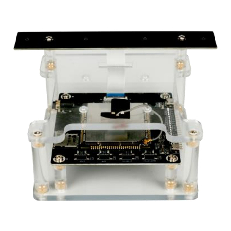
Roobo DDK2C7M1 User manual

ROOBO Smart Audio Dev Kit 2 DDK2C7M1
User Guide

COPYRIGHT © 2019 Beijing ROOBO Technology Co., Ltd.
All rights reserved. No part of this document may be modified, transmitted, transcribed, or
translated into any language in any form or by any means without the written permission of
Beijing ROOBO Technology Co., Ltd.
TRADEMARKS
ROOBO is a trademark of Beijing ROOBO Technology Co., Ltd. All other trademarks and
registered trademarks are property of their respective companies.
DISCLAIMER
Beijing ROOBO Technology Co., Ltd. owns the right to make improvements and/or changes
in this document at any time.
ROOBO provides this product to help accelerate the development of customizable in-home
assistants, in-car assistants, smart speaker, IoT devices, or other voice-enabled devices, but
not for other purposes.
Figures, photos, schematics and other information are included in this document to show
the technical specifications and/or tools instructions. If interested in mass production,
please contact ROOBO to obtain additional documents that require an NDA. ROOBO makes
no representations or warranties with respect to the accuracy or completeness of the
contents presented in this document.

Content
1.Introduction ................................................................................................................3
1.1 In the Box .........................................................................................................3
1.2 Dev Kit2 Specification ......................................................................................4
1.3 Circular 7-Mic Array .........................................................................................5
1.3.1 Mic Array Specs.....................................................................................5
1.3.2 Mic Array Board Sample and layout .....................................................6
1.4 Core Board Sample and Layout........................................................................7
1.5 Audio Data Path ...............................................................................................8
2. Development Environment........................................................................................9
2.1 Install SDK.........................................................................................................9
2.2 Compile environment configuration................................................................9
3. Filesystem operations ..............................................................................................13
4. Program guide..........................................................................................................13
4.1 Mic LEDs program ..........................................................................................13
4.2 Key..................................................................................................................14
4.3 I2C program....................................................................................................15
4.4 GPIO program.................................................................................................15
4.5 Audio operating programming.......................................................................15
5 SDK Multi-media function.........................................................................................16
1.Introduction
This Dev kit 2 (referred to as “DDK2” later in this document) is designed For Microsoft
Speech Services Complete, end-to-end system reference design.
This Circular 7-Mic array Dev Kit is a pre-tuned end-to-end reference design that enables the
commercial device manufacturers to efficiently build high-quality speech enabled devices
using Microsoft Speech Services. Developers can integrate the Microsoft Speech
Services into smart speakers, set-top boxes, and other IoT devices with this kit and leverage
premium Microsoft voice recognition technology. It can also be easily configured into a Star
4-Mic array by disabling 3 mics, for evaluating it as a lower cost device.
With the Microsoft Speech Devices SDK, it enables a range of advanced features such as
- Multi-mic array, beam forming, noise suppression, echo cancellation.
- Customizable Key Word Spotting.
- Integration with the world-class Microsoft Speech Services and Bot Framework, and more.
1.1 In the Box

•1x 6+1 digital microphone array board
•1x mainboards held by acrylic stand
•1x USB Power cable
1.2 Dev Kit2 Specification
Items
Specs
CPU
MTK MT8516AAAA/B Quad core A35 1.3GHz CPU
OS
Linux 4.4
WIFI
802.11b/g/n
Bluetooth
4.0+HS
RAM
DDR3L+NAND Flash, 1Gb(64M x 16) + 1Gb
MIC Array
7 circular array (6+1)
Audio Line out
1 x 3.5mm Line out
Data Interface
1 x Micro USB Interface
Power Interface
1 x Micro USB Interface

UART
1 x UART
I²C
1 x I²C
GPIO
3 x GPIOs
TF Card
Support, up to 32GB(FAT32)
Key
5 x Keys(Reset, Mute, Volume Up, Volume Down,
play/pause)
Power Indicator
Support Power Indicator
Mic Array Indicator
12xRGB LEDs
Work Temperature
-4~131℉(-20~55℃)
Certification
FCC ID
1.3 Circular 7-Mic Array
1.3.1 Mic Array Specs
Items
Performance

Array Type
7 circular array (6+1)
Mic Quantity
7 Analog microphone
Dimension
Mics are placed horizontally and evenly in a circle and
microphone ports face upward
Array Distance
42.5mm
Wakeup Distance
<10m
Listening Range
<5m (Room environment)
Signal to Noise Ratio
65dBA
Sampling Rate
16K
Sensitivity
-38±1 dBV @1kHz ref 1V/Pa
1.3.2 Mic Array Board Sample and layout
Items
Description
Analog MEMS Microphone
Pick up the audio from bottom,Sensitivity:-38dBV
ADC
TDM interface, 24bit ADC
Audio output
Pin pitch 0.5mm, 24 pins, Connected to core board
LED Driver
Driver RGBx12 LED
RGB LED
12xRGB LED

1.4 Core Board Sample and Layout
Items
Description
Antenna Terminal
2.4GHz Wi-Fi antenna terminal
Line out
3.5mm Audio interface
USB Debug Interface
USB 2.0 Device
Audio input
Pin pitch 0.5mm, 24 pins, Connected to mic array board

TF card socket
Insert TF card
AP
MT8516AAAA/B
DDR3L
M15T1G1664A-DEBG2CS,ESMT
NAND Flash
F59L1G81MB,ESMT
Reset key
Press and hold the button for 2 Seconds for reset
Mute key
Key for mute
Volume up key
Key for system volume up
Volume down key
Key for system volume down
Power supply
Micro USB 5V 2A supply(at least 5V 1A)
User interface
Io,uart,i2c,power interface
Notes:
We strongly recommend using high quality speakers for a better experience. If you have
noticed any static noise when the speaker is connected to the dev kit’s AUX interface, please
switch to a higher quality speaker or use the USB port of the computer to power the dev kit.
The static noise generally occurs when an adapter is used to power the dev kit, and the
quality of the speaker is low. If you want recommendations for speakers, please contact us
at rooboddk@roobo.com.
1.5 Audio Data Path
ADC
ADC
AP
Analog Mic1
Analog Mic4
Analog Mic5
Analog Mic7
.
.
.
.
.
.
TDM 16KHz
Codec
Ref Signal Channel

2. Development Environment
2.1 Install SDK
Execute the installation script for the installation.
$ sh oecore-x86_64-aarch64-toolchain-nodistro.0.sh
You can enter the installation path or select the default installation path
/usr/local/oecore-x86_64
Extracting SDK.....................
Setting it up ......done
Indicates that the compile chain was successfully installed.
2.2 Compile environment configuration
Step1- Install the USB driver
To decompress the USB driver package, double-click “DriverInstall.exe” to install it.
After installation, " android_winusb.inf " will be generated in the " C:\Program
Files\MediaTek\SP Driver\drv\Android " path.
Open“android_winusb.inf”,
add information under[MediaTek.NTx86]and [MediaTek.NTamd64] as below:
%SingleAdbInterface% = USB_Install, USB\VID_18D1&PID_D002
Please replace the " VID_18D1&PID_D002" section according to your actual device ID.
Example:
[MediaTek.NTx86]
... ...
%SingleAdbInterface% = USB_Install, USB\VID_18D1&PID_D002
[MediaTek.NTamd64]
... ...
%SingleAdbInterface% = USB_Install, USB\VID_18D1&PID_D002
After this step, if the device can be connected to the Windows PC but cannot be recognized,
please refer to the following picture to get the Device ID information.

Input the actual Device ID information into the " android_winusb.inf " file.
[MediaTek.NTx86]
... ...
%SingleAdbInterface% = USB_Install, <The ID actually identified>
[MediaTek.NTamd64]
... ...
%SingleAdbInterface% = USB_Install, < The ID actually identified >
Step2-install Python2.7.5
Decompress python2.7.5 installer and install it, add the installation path to the environment
variable after the installation is finished.
When finished, close the current CMD window, reopen a Windows console program, and
enter the following code:
python --version
Verify that version 2.7.5 is currently in use.
Step3-install pySerial
Decompress the pySerial installer and run "setup.bat" to install the pySerial tool to ensure
that no errors are reported during installation.
Step4-install ADB

Decompress the ADB toolkit, add the path to the system environment variable:
Add the dynamic link library for ADB running to the system environment,
The dynamic link library is stored under the adb directory:
AdbWinApi.dll, AdbWinUsbApi.dll
Place it in the following two directories:
C:\Windows\System32
C:\Windows\SysWOW64
Notes:
You’ll need to have the adb tool installed on your computer and make sure the adb
tool is usable.
Step5-upgrade software
Please note the directory where the image is placed in the Windows system environment. Do
not include Chinese characters and Spaces, or you will get an error.
Power off the device (unplug the power cord or plug in the cable to disconnect the power
supply), insert the small port of the Debug USB cable into the Micro USB interface of the
device, and connect the other end to your PC.
On a Windows PC, open a CMD window, go to the directory where image is stored, run
python flashimage.py, and enter into the device monitoring state.
Press and hold DDK2 Volume+ button, connect the device to PC with power USB cable. After
the device is powered on, wait for the device to be recognized to automatically start the

upgrade program and release the Volume+ button.
After the upgrade is completed, a prompt message will be displayed telling you that the
upgrade is successful. After the upgrade is successful, you will see success prompt and the
platform system will be automatically restarted.

3. Filesystem operations
1, Set filesystem access authority
The device rootfs access is read-only, so if you want to pass app or lib into the file system,
you need to modify rootfs access after logging in to the device: # mount -o remount, rw /
Change the”/”directory to read-write
Push files to devices or pull files from devices
PC push files to devices: #adb push filename dev_path
PC pull files from device: #adb pull filename local_path
4. Program guide
4.1 Mic LEDs program
You can use the APIs of libfl3236.so to control the LEDs. Wealso offer a DLL named
libfl3236.so can be used to configure LED effects.
The head file libfl3236.so declares the APIs,
sysroots/aarch64-poky-linux/usr/include/fl3236_manager.h
The sample code is as follows:
#include <stdio.h>
#include <stdlib.h>
#include <unistd.h>
#include <fcntl.h>
#include <fl3236/fl3236_manager.h>
int main(int argc, char const *argv[])
{
fl3236_init();
fl3236_set_light(FL3236_ID_ALL, FL3236_WHITE, 0xFF, CURRENT_MAX_4);
sleep(5);
fl3236_deinit();
return 0;
}
Or you can refer to the FL3236 manual to directly operate the I2C0 bus to configure the
FL3236 register.

4.2 Key
There’re five keys in DDK, these all can be configured as a normal key. The key driver reports
key events to the input subsystem, you can get key events through the standard input event
framework, and can also use libinputevent.so to get the events reported by the key driver.
The input event reported by libinputevent.so needs to be used to realize the key-press event
and the combination of key-press events。
About API,you can refer to the head file of libinputevent.so:
sysroots/aarch64-poky-linux/usr/include/input_manager.h
The sample code is as follows:
#include <stdio.h>
#include <stdlib.h>
#include <linux/input.h>
#include <inputevent/input_manager.h>
#define KEYPAD_DEV_NAME "gpio-keys"
static void key_evt_callback(struct input_event evt)
{
if ((evt.type == EV_KEY) && (evt.value == 0 || evt.value == 1)) {
printf( "key %d %s\n", evt.code, (evt.value) ? "Pressed" : "Released");
}
}
int main(int argc, char const *argv[])
{
int ret = 0;
ret = input_evt_register((char*)KEYPAD_DEV_NAME, key_evt_callback);
if (ret) {
printf( "Failed reguster key input event\n");
return -1;
}
for (;;) {
}
return 0;
}

4.3 I2C program
DDK2 leads to the i2c0 bus share reserved for developers. You can read and write from the
device node /dev/i2c0.
1. Open i2c device.
2. Set slave station address (7-bit address)
3. read/write
The sample code is as follows:
#include <stdio.h>
#include <stdlib.h>
#include <unistd.h>
#include <fcntl.h>
#include <sys/ioctl.h>
#define I2C_DEV_ADDR 0x3e
int main(int argc, char const *argv[])
{
int fd = -1;
char data[32] = {0};
fd = open("/dev/i2c-0", O_WRONLY);
ioctl(fd, I2C_SLAVE, I2C_DEV_ADDR);
write(fd, (char*)data, sizeof(data));
close(fd);
return 0;
}
4.4 GPIO program
Operate GPIO in user space, you can refer to MTK SampleCode.
4.5 Audio operating programming
Audio operations can be performed directly using the standard ALSA framework. DDK2
operates on ALSA in the following ways:
1, Use the arecord that come with ALSA
arecord -D hw:0,1 -r 16000 -c 8 -f S32_LE -d 3 /tmp/16k_8ch_32bit.wav

2, Refer to the MTK SampleCode
3, Refer to ROOBO’s package on ALSA, use libasndaudio. so to record \ play \ audio
continuous reading
About API,you can refer to the head file of libasndaudio.so:
sysroots/aarch64-poky-linux/usr/include/asndaudio.h
The sample code is as follows:
#include <stdio.h>
#include <stdlib.h>
#include <asndaudio/asndaudio.h>
int main(int argc, char const *argv[])
{
asnd_audio_record_wav(“/tmp/record.wav”,”hw:0,1”, 3, 16000, 8, SND_PCM_FORMAT_S32_LE);
asnd_audio_play_wav(“/tmp/record.wav”);
return 0;
}
5 SDK Multi-media function
MT8516 platform system runs appmainprog process in the background,Integrated audio
player function and other important peripheral functions, such as WIFI, Bluetooth, OTA, etc.
Appmainprog could be available as an application development kit, it provides an interface
layer for docking applications.
·Use Domain Socket mode to communicate with other application commands.
·The communication command is in cJson format.
· Assistant Stub thread is responsible for receiving the cJson instruction, parsing it, and
distributing it. Meanwhile, it is also responsible for packaging cJson instructions and sending
them to other applications.
As for the sending of instructions, you don't need the user to assemble the json-formatted
command package, you just need to link to libcjson.so and use the API of
libAssistantCenter.so to send the corresponding instructions.

include the head file:
sysroots/aarch64-poky-linux/usr/include/AssistantDef.h
sysroots/aarch64-poky-linux/usr/include/AssistantCmd.h
sysroots/aarch64-poky-linux/usr/include/CmdHubApi.h
The list of instructions is as follows:
typedef enum
{
//Assistant Center send to appmainprog
ASSISTANT_CMD_PLAY = 0,
ASSISTANT_CMD_PLAY_VOICE_PROMPT,
ASSISTANT_CMD_PLAY_VOICE_LOCAL,
ASSISTANT_CMD_PLAY_TTS,
ASSISTANT_CMD_PLAY_PREV_AUDIO,
ASSISTANT_CMD_PLAY_NEXT_AUDIO,
ASSISTANT_CMD_SET_VOLUME,
ASSISTANT_CMD_SET_SYSTEM_STATUS,
ASSISTANT_CMD_SET_BT_NAME,
ASSISTANT_CMD_BT_MODE_SWITCH,
ASSISTANT_CMD_BT_STOP_INQUIRY,
ASSISTANT_CMD_BT_CONNECT,
ASSISTANT_CMD_BT_UNPAIR,
ASSISTANT_CMD_BT_PAIRED_LIST_UPDATE,
ASSISTANT_CMD_BT_INQUIRY,
ASSISTANT_CMD_START_BT_PAIR,
ASSISTANT_CMD_DEL_BT_PAIRED,
ASSISTANT_CMD_OPEN_BLE,
ASSISTANT_CMD_CLOSE_BLE,
ASSISTANT_CMD_BT_POWER_ON,
ASSISTANT_CMD_BT_POWER_OFF,
ASSISTANT_CMD_PLAY_BT_MUSIC,
ASSISTANT_CMD_BT_DISCONNECT,
ASSISTANT_CMD_GET_AP_LIST,
ASSISTANT_CMD_WIFI_CONNECT,
ASSISTANT_CMD_WIFI_CONNECT_OVER,
ASSISTANT_CMD_WIFI_SETUP_RESULT,
ASSISTANT_CMD_WIFI_START_SMARTLINK,
ASSISTANT_CMD_SPEECH_START,
ASSISTANT_CMD_SPEECH_PROCESS,
ASSISTANT_CMD_SPEECH_FEEDBACK,
ASSISTANT_CMD_SPEECH_FINISH,
ASSISTANT_CMD_GET_SPEAKER_STATUS,
ASSISTANT_CMD_PAUSE,
ASSISTANT_CMD_RESUME,

ASSISTANT_CMD_OTA_UPGRADE,
ASSISTANT_CMD_ADJUST_PROGRESS,
ASSISTANT_CMD_STOP,
ASSISTANT_CMD_FACTORY_RESET_RESULT,
ASSISTANT_CMD_HFP_FREE_MIC_RESULT,
//appmainprog send to Assistant Center
ASSISTANT_CMD_PLAY_DONE,
ASSISTANT_CMD_PLAY_TTS_DONE,
ASSISTANT_CMD_SYSTEM_STATUS_CHANGE,
ASSISTANT_CMD_PLAYER_STATUS_CHANGE,
ASSISTANT_CMD_NETWORK_STATUS_CHANGE,
ASSISTANT_CMD_BLUETOOTH_STATUS_CHANGE,
ASSISTANT_CMD_BUTTON,
ASSISTANT_CMD_OTA_PROGRESS,
ASSISTANT_CMD_HFP_STATUS_CHANGE,
ASSISTANT_CMD_BT_SRC_AVRCP_CMD,
ASSISTANT_CMD_BT_BLE_MESH_STATUS_CHANGE,
ASSISTANT_CMD_KEY,
ASSISTANT_CMD_MAX
} ASSISTANT_CMD_E;
Each instruction corresponds to a different json command. You can learn the details and
implications of each command through <Appmainprog_Communication_Protocol.pdf> .
Programming reference routines or MTK SampleCode
#include "AssistantDef.h"
#include "AssistantCmd.h"
#include "CmdHubApi.h"
#include <unistd.h>
#include <fcntl.h>
static void player_callback(ASSISTANT_CMD_E cmd, char *msg, void *data)
{
printf("Monk %s recive feedback cmd[%d], msg: %s\n", __func__, cmd, msg);
if (ASSISTANT_CMD_PLAYER_STATUS_CHANGE == cmd) {
ASSISTANT_CMD_PLAYER_STATUS_CHANGE_T *play_status =
(ASSISTANT_CMD_PLAYER_STATUS_CHANGE_T *) msg;
printf("get player status change:");
printf("volume: %d", play_status->player.volume);

printf("status: %s", play_status->player.status);
printf("source: %s", play_status->player.source);
printf("audioId: %s", play_status->player.audioId);
printf("audioUid: %s", play_status->player.audioUid);
printf("audioSource:%s", play_status->player.audioSource);
printf("audioName: %s", play_status->player.audioName);
printf("audioAnchor:%s", play_status->player.audioAnchor);
printf("audioAlbum: %s", play_status->player.audioAlbum);
printf("progress: %d", play_status->player.progress);
printf("audioExt: %s", play_status->player.audioExt);
}
}
int main(int argc, char const *argv[])
{
handle_t assistant_handler = CmdHubInit(player_callback);
ASSISTANT_CMD_PLAY_VOICE_PROMPT_T voice_prompt;
memset(&voice_prompt, 0, sizeof(voice_prompt));
voice_prompt.volume = 87;
voice_prompt.feedback = true;
strncpy(voice_prompt.uri, “/tmp/test.mp3”, ASSISTANT_CMD_URI_MAX_LENGTH);
strncpy(voice_prompt.type, "normal", ASSISTANT_CMD_TYPE_LENGTH);
CmdHubSendCmd(assistant_handler, ASSISTANT_CMD_PLAY_VOICE_PROMPT,
(char *)&voice_prompt, sizeof(voice_prompt));
CmdHubDeInit(assistant_handler);
}
This device complies with part 15 of the FCC Rules. Operation is subject to the condition that
this device does not cause harmful interference (1) this device may not cause harmful
interference, and (2) this device must accept any interference received, including interference
that may cause undesired operation.
Any changes or modifications not expressly approved by the party responsible for compliance
could void the user's authority to operate the equipment.
NOTE: This equipment has been tested and found to comply with the limits for a Class B
digital device, pursuant to Part 15 of the FCC Rules. These limits are designed to provide
reasonable protection against harmful interference in a residential installation. This equipment
generates, uses and can radiate radio frequency energy and, if not installed and used in
accordance with the instructions, may cause harmful interference to radio communications.
However, there is no guarantee that interference will not occur in a particular installation.
If this equipment does cause harmful interference to radio or television reception,
which can be determined by turning the equipment off and on, the user is encouraged to try to
correct the interference by one or more of the following measures:
-- Reorient or relocate the receiving antenna.

-- Increase the separation between the equipment and receiver.
-- Connect the equipment into an outlet on a circuit different
from that to which the receiver is connected.
-- Consult the dealer or an experienced radio/TV technician for help.
To maintain compliance with FCC’s RF Exposure guidelines, This equipment should be
installed and operated with minimum distance between 20cm the radiator your body: Use only
the supplied antenna.
FCC ID: 2ASEF-DDK2C7M1
Table of contents
Other Roobo Microcontroller manuals