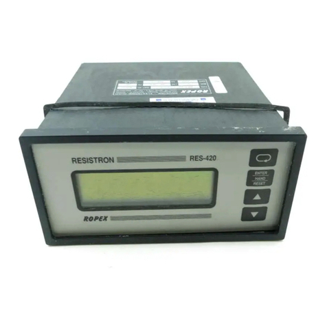
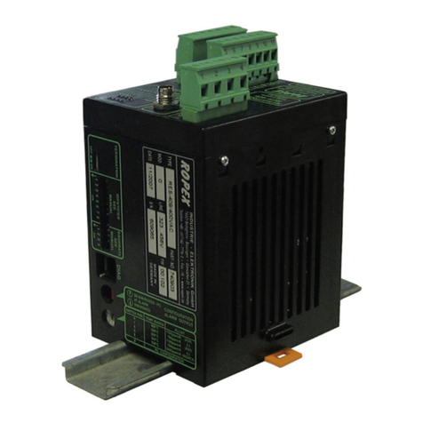
Ropex Resistron RES-242 User manual

Industrie - Elektronik GmbH .Gansäcker 21 .D-74321 Bietigheim-Bissingen
Telefon (07142) 7776-0 .Telefax (07142) 7776-19 .
ROPE X
ROPE X
ROPE X
ROPE X
INDUSTRIE
-
ELEKTRONIK
TEMPERATURE CONTROLLER
FOR HEATSEAL BANDS
TO SEAL PLASTIC FILMS
Designed for Easy Mounting on the Control Panel
Analog Temperature Meter
Integrated Heat Sealing and Cooling Programs
Numerous Programming Functions
Easy Installation and Operation
Built in Timers
Preferred for General Applications
FEATURES
TABLE OF CONTENTS
1. APPLICATION AND SHORT DESCRIPTION
2. FUNCTIONS OF THE RES-241/242
2.1 Control Function
2.2 Zero Calibration
2.3 Start-Function
2.4 Cycle Timing
2.5 Alarm Function
2.5.1 Alarm Signal
2.5.2 Reset
3. CONTROLS AND INDICATORS
4. PROGRAMMING OF THE TIMING FUNCTIONS
5. EXAMPLE
6. WIRING DIAGRAM
7. OPERATING INSTRUCTIONS
8. HEATSEAL ELEMENT
9. HEATING IMPULSE, TIMING
10. OUTLINE DIMENSIONS
11. SPECIFICATIONS
12. GENERAL INSTALLATION INSTRUCTIONS
with Alarm
RES-242RES-242
without Alarm
RES-241RES-241
RESISTRONRESISTRON
09.02

ROPE X
ROPE X
ROPE X
ROPE X
INDUSTRIE - ELEKTRONIK GmbH
Page 2
1. APPLICATION AND SHORT DESCRIPTION
As all other , this unit is used to control
the temperature of heating elements (heatseal bands,
beaded bands, cutting wires, etc.) by monitoring the
resistivity of the heating elements. Precision
measurement together with high response produces
perfect temperature control during the film sealing
processes. With a correctly installed system, the
temperature is controlled with an accuracy of ±3%.
By changing settings, this controller can be used to
control heating elements with a range of resistances from
a few milliohms to several ohms. Therefore, this universal
controller may be used in a variety of general applications
for controlling the heatseal elements in:
vertical and horizontal f/f/s machines
pouch filling and sealing machines
film wrapping machines
pouch making machines
group packaging machines, etc.
The controller, have all the known
functions of the RES-200 series, plus two digital timers,
sealing time and cooling time. This eliminates additional
external usage of timers to control heat impulse timing
and jaw action.
This additional feature makes the controller very suitable
for use in:
hand operated and table top machines
heatsealing sealing presses
L-sealers
RES controllers
RES-241 / 242,
As shown in Section 5, a complete sealing station can be
controlled with this controller without using additional
electrical components.
All parameters related to the sealing phase, like time and
temperature, can easily be selected by use of the digital
switches on the front panel of the unit.
The desired values are entered according to the
appropriate units, i.e. and/or .
Numerous functional sequences can be programmed
with the dip switches mounted on side of the controller.
This allows the user to select the best program for any
specific heatsealing process.
Processes that are primarily temperature dependent can
be programmed, e.g. closing of the jaw only after full
sealing temperature has been reached; or opening of the
jaws only after the cooling to a pre-determined
temperature has been reached.
(see Section 4: Timing Functions Programming).
The cycle sequence can be observed during operation by
means of the analog temperature meter and the LED´s
for heating and cooling.
Both the and controllers are identical
with the exception of the "alarm function" that is contained
only in the Model RES-242.
°C sec
RES-241 RES-242
2. FUNCTIONS OF THE RES-241 / 242
CONTROL FUNCTIONS
The controller operates in two different modes: monito-
ring or controlling.
If there is , the controller will only
monitor the resistance of the heating element without
raising the temperature. Resistance monitoring is
accomplished by means of short low power pulses every
10 cycles of the line frequency. It is in this mode that the
"Z" calibration is performed. In the monitoring mode, the
"ON" LED blinks red. When a START signal is applied,
LED "ON" becomes steady state red.
no START signal
The controller then goes into the regulating mode and
increases the temperature of the heating element to the
desired set point as rapidly as possible.
The maximum secondary voltage is initially supplied to
the heating element and then subsequently reduced by
the phase control as the preset maximum temperature is
approached.
A high sampling rate together with virtually instant
feedback gives the controller an instantaneous response
capability.
2.1

ROPE X
ROPE X
ROPE X
ROPE X
INDUSTRIE - ELEKTRONIK GmbH
Proper operation depends upon the accurate calibra-tion
of the system. Because the resistance of the heatseal
element may very depending upon its precise length and
cross-section, the calibration ("Z" point) must be checked
and reset after each change or replacement of the
heatseal element.
(see Sect. 8, "Heatseal Element" and Sect. 7, "Operating
Instructions")
A feature prevents the overheating of the
heating element when the controller is improperly
calibrated, set below the "Z" point.
Should this occur, the RES-241 controller will not accept
the START signal, while the RES-242 will go into "ALARM"
and shut down.
"START-Lock"
Page 3
ZERO CALIBRATION
ZERO calibration is the adjustment of the controller to the
resistance of the cold heatseal element.
This calibration must be performed with the heatseal
band at room temperature. The hand of the analog
temperature meter is set to "Z" by turning the "ZERO"
adjustment trimmer with the heatseal element at ambient
temperature and the controller in the monitoring mode.
("Z" = 20°C/68°F). After calibration the hand should rest
quietly at "Z".
START-FUNCTION
A heating cycle is initiated with the start function. The
controller then switches from the monitoring mode to the
regulating mode, and concurrently starts the timing
cycles. The START signal can be given in three different
ways:
NOTE - When using new heating elements:
After a few temperature cycles the resistance of the
element will be reduced, the calibration may no longer be
correct. When this occurs, allow the heating element to
return to ambient temperature and reset the meter to "Z"
by using the Zero Trimmer.
100 200
300
0
Z
°C
Mechanical zero adjustment. Do not move!
START ENABLE
when needle is
below zero
2.2
2.3
by pressing "HAND" on the front panel
by closing the circuit between terminals 2 and 7,
with potential free contact.
by supplying 24VDC to Terminals 3 and 4
Control Function (Continuation)
full
heat current
reduced
heat current
temperature display
controller
sampling sampling
OFF OFF Start
ON
20°C
set point
Current
Temp.
Start regulating mode
sampling
pulses
actual
temperature

ROPE X
ROPE X
ROPE X
ROPE X
INDUSTRIE - ELEKTRONIK GmbH
Page 4
ALARM FUNCTION (RES-242 only)
ALARM SIGNAL
To increase the reliability of operation and to assure
adequate seals, the RES-242 controller contains a
comprehensive monitoring system that will send an
alarm signal (LED "ALARM" will turn red) and activate the
alarm relay when:
a) the heatseal element breaks, or any discontinuity in
the secondary circuit occurs.
b) ONE of the heatseal elements breaks when two
bands are mounted parallel.
c) A short circuit occurs at the heatseal element
d) Any discontinuity occurs in the monitoring wiring of
the heatseal element or the current transformer.
e) Any overheating of the heatseal element by 20%
above the controller´s operating temperature range
f) "Z" point is incorrectly set.
(see "START Function" and "Start Block")
To assure a trouble free "ZERO" calibration, functions e)
and f) will only activate after the start signal is given.
Other reasons for an ALARM signal are:
RESET
The controller can be reset - after the cause of the alarm
has been corrected - by pushing the "RESET" button or
by turning off the main power by at least 1 second.
Functions of the RES-241/242 (Continuation)
CYCLING TIMING
Heating and cooling cycle time follow each other.
Depending upon the program selected by use of the DIP
switch, the either starts with the "START"
signal or when the heating element reaches the pre-set
temperature.
(see Section 4 "Timing Functions Programming").
The always starts at the end of the
heating cycle. The maximum time duration for heating or
cooling is 9.9 seconds. Depending upon the program
selected, the duration of the cooling cycle may be set to
heating time
cooling cycle time
be a funtion of time or temperature. The cooling cycle may
be set to end when a pre-set temperature is reached, that
means that the relay K1 will drop out when the temperatu-
re drops below the pre-select level. The selection is done
by means of the 2 position digital selector switch in °C x 10
in increments of 10 degrees.
Selection 08 = 80 °C
Selection 12 = 120 °C
EXAMPLE:
2.4
2.5
2.5.1
2.5.2
Taste "RESET" oder Abschalten der Netzspannung
für mind. 1 sec und Wiedereinschalten.
incorrect programming of DIP switches in the
for U voltage selection.
improper position of the frequency jumper.
improper power supply voltage.
internal malfunction.
2
In the case of an alarm, the LED "ALARM" will turn red, the
controller output will be disabled, and the ALARM relay
will close between terminals 5 and 6.

ROPE X
ROPE X
ROPE X
ROPE X
INDUSTRIE - ELEKTRONIK GmbH
Page 5
Temperature Meter
in °C
"Z" pt. is at 20 °C
Preset Temperature
Digital Switch in °C
max.299°C
Select Sealing
Time
in sec x 0,1
Select Cooling
Time
in Sec. x 0,1.
max.9,9sec
or depending upon
the DIP switch
programming
Select Cooling
Jumper for
Frequency Selection
LED GREEN for
Cooling Time
LED RED for
Sealing Time
DIP Switch
to select U2
DIP Switches
for Programming of
Sealing Process
12345 678910
ON
10 Turn "ZERO" Trimmer
for
setting Calibration to "Z"
LED is RED when
START "HAND" BUTTON
will start controller with a
full timing cycle
LED RED, blinks in
monitoring mode,
remains when
controller starts
(heating cycle)
LED YELLOW
Indicates status of
K1 Output Relay;
ON when relay is
closed
315 18910
11
13
12
5
4
6
7
2
14
3. CONTROLS AND INDICATORS
on RES-242 only

ROPE X
ROPE X
ROPE X
ROPE X
INDUSTRIE - ELEKTRONIK GmbH
Page 6
Relay K1 will activate concurrently with the
start signal to the controller, and release after
The heating cycle time begins with the start
Relay K1 will activate when the heatseal band
reaches the pre-set temperature, and release
after the cooling cycle times out.
The heating cycle starting time begins when
the heatseal band reaches the pre-set
temperature.
Relay K1 activates to produce a "signal pulse"
( .5 sec.) after the completion of the cooling
cycle.
Relay K1 activates concurrently with the start
signal to the controller and releases when the
preset cooling temperature of the heatseal
band has been reached.
Relay K1 will activate when the heatseal band
reaches the pre-set temperature, and release
after the pre-set cooling temperature has
been reached.
12345 678910
ON
12345 678910
ON
A
F
12345 678910
ON
12345 678910
ON
B
G
12345 678910
ON
C
12345 678910
ON
D
12345 678910
ON
E
12345 678910
ON
H
4.1 PROGRAMMING THE OUTPUT RELAY
tK= Cooling Time tH= Heating Time K1 = Relay
4.2 PROGRAMMING THE HEATING TIME
4.3 PROGRAMMING FOR CONSTANT HEAT
At the initial start signal the controller will be
activated to heat and control the heatseal
band temperature until the power supply to
the controller is disabled. The K1 timer
sequence is independent of this and can be
START
TEMP
K1
K1
K1
K1
K1
tH
tH
TEMP
TIME
tHtK
0,5
4. TIMING FUNCTIONS PROGRAMMING
(LED: Green ) (LED: Red ) (LED: Yellow)
The output relay may be programmed for 5 different modes of timing sequence,
for activating the seal jaws or other functions, by setting the DIP switches on the
side of the controller.
The heating time can be programmed for 2 different modes by using the DIP
switches on the side of the controller.

ROPE X
ROPE X
ROPE X
ROPE X
INDUSTRIE - ELEKTRONIK GmbH
Page 7
Magnetic Valve
Sealing jaw
Heatseal band
Cylinder
Plastic film
Plastic film
Opposing jaw
Foot switch
5. EXAMPLE
PNEUMATICALLY OPERATED PLASTIC FILM HEATSEALING DEVICE WITH RES-242
CONTROLLER, MAGNETIC VALVE AND IMPULSE START BY FOOT PEDAL.
The foot pedal provides the start signal to the controller, the heating cycle of the element starts.
After reaching the pre-set temperature relay K1 closes, the magnetic valve is activated and the
sealing jaw closes. Simultaneously, the heating cycle time is started.
When the heating cycle ends, power to the heating element is disabled, and the
begins (jaws remain closed). At the end of the , relay K1 opens, the valve is
deactivated and the jaws open.The sealing cycle is complete.
cooling cycle
cooling cycle time
This program is the same as example 1 until the end of the heating cycle. At the end of the heating
cycle, the cooling cycle starts and ends only when the has drop below the
temperature pre-selected on the "COOL" digital selector switch (digits x 10 in °C).
Only then, the relay K1 opens and allows the jaw to open.
This means, the complete sealing cycle does not end at a preset but with a pre-
selected .
This program is advantageous when the jaws heat and cool slowly. The cooling time is
automatically prolonged and the seal is consistently good.
cooling temperature
cooling time
cooling temperature
12345 678910
ON
12345 678910
ON
EXAMPLE 1: Controller Program B
EXAMPLE 2: Controller Program E
Sequence:
Sequence:
Start
Controller Relay K1

ROPE X
ROPE X
ROPE X
ROPE X
INDUSTRIE - ELEKTRONIK GmbH
Page 8
12 11198765431213141516 17 18
START
SWITCH
+
-
START 24VDC
ALARM
INTERNAL ALARM RELAY
RES-242 ONLY
(Normally open)
max.
50V/0,2A
U
IRR
R
CURRENT
TRANSFORMER
HEATSEAL
BAND
U
U1
2
PRI.
SEC.
LINE
RELAY - TERMINALS
100 VDC / 1,5A
240 VAC / 1,5A
0
K1
2x 47nF/560R
POWER
TRANSFORMER
6. WIRING DIAGRAM
twisted
FILTER

Programming switch 14 must be set to achieve the desired program
sequence. (see Section 4)
Set the DIP switch 15 to select the secondary voltage range that will
be used. With extreme low resistance heatseal elements (less than
100mOhm) or with extremely high secondary currents (larger than
80A) switch No. 5 .must also be ON
ROPE X
ROPE X
ROPE X
ROPE X
INDUSTRIE - ELEKTRONIK GmbH
Connect power.
LED "ON" 5 will blink and LED "ALARM" 7 must be
off (only on the RES-242).
: If the controller goes immediately intoNOTE
Page 9
7. OPERATING INSTRUCTIONS
7.1
7.2
7.3
7.4
7.5
7.6
Examine the controller and determine that the power to be supplied to the
controller is in agreement with the controller specification.
50Hz
50Hz
60Hz
60Hz
50Hz
60Hz
Jumper 13 for the frequency
option (50/60Hz) must be set
into its proper position.
12345
ON
12345 678910
ON
Connect the controller as shown in the wiring
diagram. No special attention must be given to
the polarity of the measuring wires for current
and voltage as well as the transformer´s primary
or secondary.
(Section 12).
Make sure that there is "START" signal at
See General Installation Instructions
VERY IMPORTANT
NO
"ALARM" and LED "ALARM" is red, all wiring system
must be rechecked for correct and tight connections.
If ALARM continues also refer to Section 2.5
"ALARM FUNCTION".
12345
Switch
No.
20-603- 10 8- 30 50-80
U2V
()
12 13 14 15
U
U1
2
PRIM.
SEK.
NETZ
SCHWEISSTRAFO
LINE
V
Hz
50/60
(see Section 3)
12345
ON
Example: for 42V secondary voltage and an expected initial current of 120A (I = U / R ),
DIP SWITCH 3 5 must be ON.
2MAX 2 SEALBAND
and
1x
12 11198765431213141516 17 18
START
SWITCH
+
-
START 24VDC
ALARM
INTERNAL ALARM RELAY
RES-242 ONLY
(Normally open)
max.
50V/0,2A
U
IRR
R
CURRENT
TRANSFORMER
HEATSEAL
BAND
U
U1
2
PRI.
SEC.
RELAY - TERMINALS
100 VDC / 1,5A
240 VAC / 1,5A
0
K1
2x 47nF/560R
POWER
TRANSFORMER
twisted
LINE
FILTER

ROPE X
ROPE X
ROPE X
ROPE X
INDUSTRIE - ELEKTRONIK GmbH
Within this cycle the yellow LED 12 is on depending
upon the program setting of the DIP switches 14 and
indicates the switching action of the relay K1. Also refer to
Section 4.1 "Programming of the Output Relay".
The Analog Meter hand movements must be steady and
rhythmical, indicating the temperature increase and
decrease of the heatseal element temperature during the
heating the cooling cycles.
After several heating cycles, let the heatseal element cool
down completely and check the "Z" calibration; some
adjustment might be needed.
Now the controller is ready for full operation.
Once started, a timing sequence cannot be interrupted
nor delayed. A new sequence can only be started with a
new signal after completion of the previous sequence
When turning on the controller, follow the correct
sequence. - power, the signal.
both together or in reverse sequence. However,
the temperature may be pre-set before turning on the
NOTE:
FIRST THEN START
NEVER
LED 5 "ON" changes from blinking to constantly on;
heating cycle starts.
depending upon the programming, the LED "HEAT"
8 can be on simultaneously with LED 5 , or only after
the preset temperature has been reached.
starting with the heating process the hand should
show a steady temperature rise to the preset level
where it should stop until the sealing time is lapsed.
at the end of the sealing time the LED 8 will turn off
and the green LED "COOL" 10 is illuminated
(beginning of the cooling time). At the same time the
LED 5 "ON" will return to blinking. The hand on the
meter will decline indicating the cooling of the heatseal
element.
after the cooling time, or when the preset cooling
temperature (digital selector switch 11 has been
reached, LED 10 ) turns off.
Page 10
Turn the "ZERO" Trimmer 2 so that the meter hand rests
on "Z"
.
Which way to turn?
If the hand is on the left side, turn the trimmer clockwise; if
the hand is on the right side, turn the trimmer counter
clockwise. If the "ZERO" calibration is not possible, the
meter hand remains on the right side, pass the wire
-only with the heatseal element at ambient
temperature
through the current transformer a second
time; in extreme cases a third pass might
be necessary. This situation might occur
when the heatseal element is very long
and thin (high resistance).
after trying each pass
through the current transformer.
RECALIBRATE
7.7
7.8
- Select any temperature (example 150°C) on the digital
selector switch 3
- Select the sealing time (example 3.0sec) on the digital
selector switch 9
- Select the cooling time (example 5.0sec) on the digital
selector switch 11
- Press "HAND" button 4 ,and the following cycle
begins:
Operating Instructions (Continuation)
8. HEATSEAL ELEMENT
The heatseal element is an important component of the
control system since it is simultaneously the sealing
element and the temperature sensor. There are so many
different shapes and size of heatseal elements that we
cannot discuss them all here, however, some very
important physical and electrical characteristics are
emphasized here.
is reduced by approx. 2 or 3%. This rather small
change in resistance however results in a zero point
discrepancy of 20 - 30°. Therefore, it is necessary to re-
adjust the zero point after a few heating cycles.
An overheated (burned out) heatseal element cannot
be used and must be replace because of an irreversi-
ble change in metallurgy at high temperatures.
A very important option is to copper plate or c/a coat
the ends of the heatseal elements.
This will result in better temperature control and
extended "life" of the heatseal element as well as of the
Teflon cover or coating
NOTE: When heatseal bands are replaced the system must be recalibrated as described in 7.7
HEATSEAL BAND REPLACEMENT
The controlling principle of the system demands that
only Alloy-20 heatseal elements be used.
During the first heat up to 200 - 250°C the heatseal
element will experience a one time change in resistan-
ce (burn in effect). The resistance of the cold element
8.1
2x
Stand by mode. Monitoring pulses.
Under certain conditions, sealing is also possible with the
so-called procedure. In this mode, the
remaining heat in a sealing element is calculated to be
just enough for the sealing process. This means that in
the timing process, the temperature drops in phase 4 .
The current is cut off when the jaws touch. The heat flows
into the film and "unloads" the heat stored in the heatseal
element, which results in a faster cooling. For this method
to be effective the thickness, therefore the mass, of the
heatseal element must be great enough to hold the
required total heat.
rest-heat
The pre-set temperature should always be attained
before the sealing jaws make contact. This allows the
sealing element to expand without constraint and
eliminates stressing of the heatseal element ends
(phase 2 ).
ROPE X
ROPE X
ROPE X
ROPE X
INDUSTRIE - ELEKTRONIK GmbH
Page 11
9. IMPULSE SEALING
When the impulse sealing method is employed the start
signal is synchronized with the operating cycles of the
machine. Every heating cycle is followed by a cooling
cycle . It is Important that the cooling is
effected with jaws closed so that the seal can set and
gain strength and good appearance befor the jaws are
opened. This method is preferred if adequate sealing
time is availabel because the strength and appearance
of the seal are optimized.
Since the heat sealing is a thermodynamically reversible
procedure and is often influenced by time constraints, it
is very important that the relevant parameters; tempera-
ture, time and pressure are very carefully synchronized.
The following diagram shows an example of the timely
setting of each parameter.
Basic rules for Impulse Heatsealing:
A.
with jaws closed
B.
PRECISION TIMING FOR PERFECT HEATSEALS
High performance productivity with perfection
requires coordinated timing between the heatseal
impulse and the jaw action.
The timing chart below describes the relationship of (A) Heating and cooling
cycles. (B) Heatseal Band temperature. (C) Heatseal Jaw action. (D) Power Output.
START
HEATING CYCLE TIME
COOLING CYCLE TIME
TEMP.
SET POINT
COOLING
Phase
1
1
2
2
3
3
4
4
4
5
5
6
6
t
t
t
JAW ACTION
S
S
OPEN OPEN
CLOSING
CLOSED
OPENING
CURRENT
(= LED OUTPUT)
I2
IMAX
MONITORING
PULSE
MONITORING
PULSE
A
B
C
D
Phase :
Jaws are opening.
Cooling phase:
set-up
Start of cooling time. Time must be allowed for the
seal to befor jaws are opened.
Power output is . Temperature remains at set point.controlled
While jaws are closing, the heatseal band temperature rises to the set
point so that full temperature is reached befor the jaws closed.
START is "OFF" open. Jaws are and the heatseal band is cooling
from the previous cycle. (Monitoring Mode)
Diagram D shows the rate of current flow during a sealing phase.
This can also be measured with an amp-meter.
Phase :1
Phase :2
Phase :3
Phase :4
Phase
und :
Phase
5
6
Heatseal process: Start of sealing time. Time must be allowed for the
heat to full penetrate the material to be sealed.
9.1
The system should be designed to drive the heatseal
element to the preset temperature in minimum time.
The total system, principally the secondary voltage,
must be optimized to achieve the best result.
.
C.
Our application service will give you the necessary
data for your special application
The cool down of the heatseal element while still
under the force of the jaws is the main advantage of
impulse sealing (phase 5 ). At the completion of the
heatseal cycle, most of the excess heat will be
absorbed by the jaws. Cooling of the jaws is
sometimes recommended so that they can absorb
enough heat from the heatseal element quickly.
Contrary to the constant heat mode, good thermal
conductivity between the sealing element and the
jaws must be assured by using a thin backup material
behind the heatseal element.
Notice that it is possible to energize the heatseal band
prior to jaw closing because the temperature controller
eliminates the risk of overheating.
Controller "ON" heating up with full secondary voltage,
maximum power.
Controller "ON" and regulating to maintain the preset
temperature while the jaws are still open.
Controller "ON" and regulating. Increased power is
being supplied to maintain the preset temperature
during the sealing process.
Controller "OFF" and the heatseal band is cooling,

ROPE X
ROPE X
ROPE X
ROPE X
INDUSTRIE - ELEKTRONIK GmbH
Page 12
30,0
11,8
38,0
10,0
45,0
60,0
22,0
68,0
2x Quick Connect
Terminals
6,3 x 0,8mm
Snap-on base for DIN-rail 35 x 7,5mm oder 35 x 15mm nach DIN EN 50022
10. OUTLINE DIMENSIONS
147
75
60Hz 50Hz
*)
130
43
32
30
136
147
PANEL JUMPER FOR LINE FREQUENCY
*) 20mm = TYPE RES-XXX - 0
45mm = TYPE RES-XXX - 1
CLEAR COVER GASKET MOUNTING BRACKET TERMINAL BLOCKS
OUTLINE DIMENSIONS CLEAR COVER
138 x 68
+1,0
-0 -0
+0,7
DIP SWITCH
to select U2
PANEL CUTOUT CURRENT TRANSFORMER

ROPE X
ROPE X
ROPE X
ROPE X
INDUSTRIE - ELEKTRONIK GmbH
Housing, with clear cover, designed for mounting into the control panel
DIN-Format: 72 x 144 mm
Standard 230 VAC
Option 115 VAC or 400 VAC
+10% / -15%
50Hz or 60Hz, selected with jumper
±1Hz
Set with 3 digit selector switch, Range 0...299 °C [or 0...499 °C ]
Resolution 1K
2 digit selector switch, Range 0...9,9 sec
Resolution 0,1 sec
Set with 2 digit selector switch, Range 0...300 °C [or 0...500 °C ]
Resolution 10K
OFF: 0... 2 VDC, ON : 5...30 VDC; typ. 8 mA at 24V
OFF: Contacts open, ON: Contacts closed; typ. 0,13mA
Potential free contact, max. 50V / 0,2A; Contact closed upon Alarm
Potential free switching contact
with R/C safety switch, max. 100VDC / 1,5A or 240VAC / 1,5A
In monitoring mode: Every tenth cycle 200 msec at 50Hz
or 166 msec at 60Hz
In controlling mode: Every voltage cycle 20 msec at 50Hz
or 16,6 msec at 60Hz
Calibrated for heating elements with T = +10 x 10 K
+5 °C bis +45 °C
Terminal Blocks, with plug in connectors
IP 20
Controller 1,2 kg (2,64 Ibs.), Current Transformer 0,15 kg (0,33 Ibs.)
K
-4 -1
Page 13
11. TECHNICAL SPECIFICATIONS
Type of Construction:
Operating Range:
of Line Voltage
Line Frequency:
Operating Range:
of Line Frequency
Sealing Temperature:
Sealing- and Cooling Time:
Cooling Temperature Set Point:
Start Signal, Terminals 3 and 4:
or
Terminals 2 and 7:
Alarm Output:
(RES-242 only)
Output Relay K1:
Sampling Rate:
Calibration:
=primary current of the
heatseal transformer
Ambient Temperature:
Electrical Connections:
Protective Cathegory:
Line Voltage:
Maximum Load Current: Operating
Mode
Constant
(average)
Impulse
20% duty cycle
TYPE
RES-24X-0
(Standard) RES-24X-1
5A
25A
15A
20A Main Application

ROPE X
ROPE X
ROPE X
ROPE X
INDUSTRIE - ELEKTRONIK GmbH
Page 14
11.1 HOW TO ORDER
EXAMPLE:
RES-24X-X-X/230V-50/60 Hz
Line Voltage
Standard: 230 VAC
Option: 115 VAC oder 400VAC
Temperature Range
X = 3 = 0 - 300°C
X = 5 = 0 - 500°C
X= 0
X= 1
Maximum Load Current
(see Technical Specifications)
X = 1 = Alarm
X = 2 = Alarm
without
with
SERIES "RESISTRON"
Supply : Controller with clear front panel, gasket and mounting brackets
Current transformer
^
^
^
^

INSTALLATION - INSTRUCTIONS
Line
Transformer
Current transformer
U1
Prim.
Heatseal band R= f (T)
U2
Sec.
A
F
Avoid long
cable length
Sufficient wire
cross section
Heatseal element
with coppered ends
Use heatseal bands with appropiate
temperature coefficient
No additional
resistances in the
secondary circuit
Observe the
number of
passes
twisted
No push
on
connectors
Current measuring wires I
R
Correct dimensions of transformer
- secondary voltage
- power
- duty cycle
Controller
Set DIP-Switch
into correct
position
Set jumper for
line frequency
into proper
position
Voltage measuring
wire U connected
directly to the ends
of heatseal elements
R
INDUSTRIE - ELEKTRONIK GmbH
This manual suits for next models
1
Table of contents
Other Ropex Controllers manuals

Ropex
Ropex Resistron RES-220 Quick start guide

Ropex
Ropex RESISTRON RES-408 User manual

Ropex
Ropex Resistron RES-5011 User manual

Ropex
Ropex CIRUS UPT-6010 User manual

Ropex
Ropex RESISTRON RES-409 User manual

Ropex
Ropex RESISTRON RES-406 User manual

Ropex
Ropex RESISTRON RES-5010 User manual

Ropex
Ropex RES-225 User manual

Ropex
Ropex RESISTRON PD-3 User manual

Ropex
Ropex Resistron RES-430 Series User manual