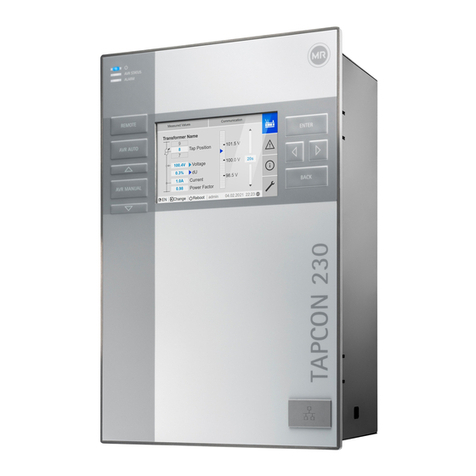
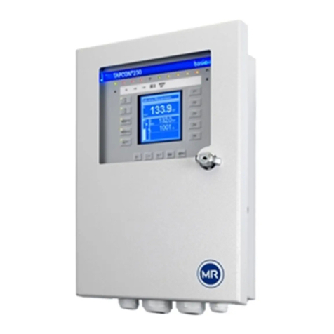
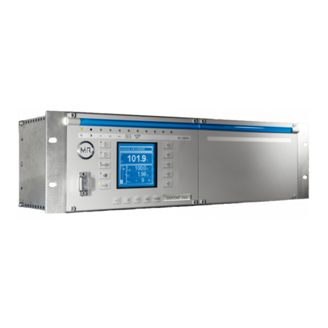
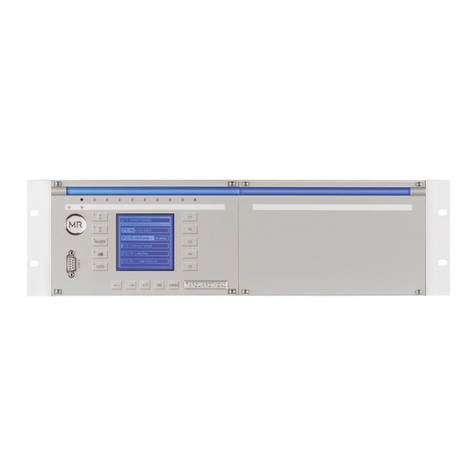
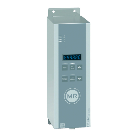
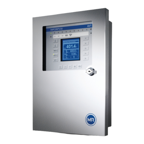
MR TAPCON 230 basic User manual

Voltage Regulator
TAPCON®230 basic
Operating Instructions
2117246/05 EN

© All rights reserved by Maschinenfabrik Reinhausen
Dissemination and reproduction of this document and use and disclosure of its content are strictly prohibited
unless expressly permitted.
Infringements will result in liability for compensation. All rights reserved in the event of the granting of patents,
utility models or designs.
The product may have been altered since this document was published.
We reserve the right to change the technical data, design and scope of supply.
Generally the information provided and agreements made when processing the individual quotations and orders
are binding.
The original operating instructions were written in German.

Table of contents
Maschinenfabrik Reinhausen GmbH 2019 32117246/05 EN TAPCON®230 basic
Table of contents
1 Introduction......................................................................................................................... 7
1.1 Manufacturer....................................................................................................................................... 7
1.2 Subject to change without notice........................................................................................................ 7
1.3 Completeness..................................................................................................................................... 7
1.4 Safekeeping........................................................................................................................................ 7
1.5 Notation conventions .......................................................................................................................... 7
1.5.1 Hazard communication system .............................................................................................................................8
1.5.2 Information system................................................................................................................................................9
1.5.3 Instruction system .................................................................................................................................................9
1.5.4 Typographic conventions ....................................................................................................................................10
2 Safety................................................................................................................................. 11
2.1 General safety information................................................................................................................ 11
2.2 Appropriate use ................................................................................................................................ 11
2.3 Inappropriate use.............................................................................................................................. 11
2.4 Personnel qualification...................................................................................................................... 11
2.5 Operator's duty of care ..................................................................................................................... 12
3 IT security.......................................................................................................................... 13
4 Product description.......................................................................................................... 14
4.1 Scope of delivery .............................................................................................................................. 14
4.2 Function description of the voltage regulation .................................................................................. 15
4.3 Performance features ....................................................................................................................... 16
4.4 Operating modes .............................................................................................................................. 17
4.5 Hardware .......................................................................................................................................... 17
4.5.1 Name plate..........................................................................................................................................................18
4.5.2 Operating controls...............................................................................................................................................19
4.5.3 Display elements.................................................................................................................................................20
4.5.4 Serial interface ....................................................................................................................................................22
4.5.5 MIO card module.................................................................................................................................................23
5 Packaging, transport and storage .................................................................................. 24
5.1 Packaging......................................................................................................................................... 24
5.1.1 Purpose...............................................................................................................................................................24
5.1.2 Suitability, structure and production ...................................................................................................................24

Table of contents
Maschinenfabrik Reinhausen GmbH 201942117246/05 ENTAPCON®230 basic
5.1.3 Markings..............................................................................................................................................................24
5.2 Transportation, receipt and handling of shipments........................................................................... 24
5.3 Storage of shipments........................................................................................................................ 26
6 Mounting ........................................................................................................................... 27
6.1 Preparation ....................................................................................................................................... 27
6.2 Mounting device................................................................................................................................ 27
6.2.1 Flush panel mounting..........................................................................................................................................29
6.2.2 Wall mounting with mounting brackets................................................................................................................30
6.2.3 Cap rail mounting ................................................................................................................................................31
6.2.4 Wall mounting .....................................................................................................................................................32
6.2.5 Removing the door..............................................................................................................................................33
6.3 Connecting device ............................................................................................................................ 34
6.3.1 Cable recommendation .......................................................................................................................................35
6.3.2 Information about laying fiber-optic cable ...........................................................................................................35
6.3.3 Electromagnetic compatibility..............................................................................................................................36
6.3.4 Connecting cables to the system periphery ........................................................................................................39
6.3.5 Supplying the voltage regulator using auxiliary voltage ......................................................................................40
6.3.6 Wiring device.......................................................................................................................................................40
6.3.7 Checking functional reliability..............................................................................................................................41
7 Commissioning................................................................................................................. 42
7.1 Setting the display contrast............................................................................................................... 42
7.2 Setting parameters ........................................................................................................................... 42
7.2.1 Setting the language ...........................................................................................................................................43
7.2.2 Setting further parameters ..................................................................................................................................43
7.3 Function tests ................................................................................................................................... 44
7.3.1 Checking control functions ..................................................................................................................................44
7.3.2 Checking additional functions .............................................................................................................................45
8 Operation........................................................................................................................... 49
8.1 Key lock ............................................................................................................................................ 49
8.2 General............................................................................................................................................. 49
8.2.1 Setting device ID .................................................................................................................................................49
8.2.2 Setting the baud rate...........................................................................................................................................50
8.2.3 Setting the switching pulse time..........................................................................................................................50
8.2.4 Setting operations counter ..................................................................................................................................52
8.2.5 Dimming display..................................................................................................................................................53

Table of contents
Maschinenfabrik Reinhausen GmbH 2019 52117246/05 EN TAPCON®230 basic
8.2.6 Activating/deactivating the automatic key lock....................................................................................................53
8.2.7 "Function monitoring" message for monitoring messages <30 V........................................................................54
8.2.8 Setting motor runtime monitoring ........................................................................................................................55
8.2.9 Activate manual mode/auto mode.......................................................................................................................57
8.2.10 Activating Local/Remote .....................................................................................................................................58
8.2.11 Setting the COM1 password ...............................................................................................................................58
8.2.12 Setting the password duration.............................................................................................................................59
8.3 NORMset.......................................................................................................................................... 59
8.4 Control parameters........................................................................................................................... 61
8.4.1 Setting desired value 1...3...................................................................................................................................63
8.4.2 Selecting a desired value ....................................................................................................................................64
8.4.3 Bandwidth ...........................................................................................................................................................65
8.4.4 Setting delay time T1 ..........................................................................................................................................66
8.4.5 Setting control response T1 ................................................................................................................................67
8.4.6 Setting delay time T2 ..........................................................................................................................................68
8.5 Limit values....................................................................................................................................... 69
8.5.1 Setting undervoltage monitoring U<....................................................................................................................69
8.5.2 Setting overvoltage monitoring U>......................................................................................................................72
8.5.3 Setting overcurrent monitoring I>........................................................................................................................74
8.5.4 Set undercurrent monitoring I<............................................................................................................................75
8.5.5 Activate/deactivate active power monitoring .......................................................................................................76
8.6 Compensation................................................................................................................................... 76
8.6.1 Line drop compensation......................................................................................................................................76
8.6.2 Z compensation...................................................................................................................................................79
8.7 Transformer data .............................................................................................................................. 81
8.7.1 Setting the primary transformer voltage ..............................................................................................................82
8.7.2 Setting the secondary transformer voltage .........................................................................................................82
8.7.3 Setting primary transformer current ....................................................................................................................83
8.7.4 Setting the current transformer connection .........................................................................................................84
8.7.5 Setting the phase difference for the current transformer/voltage transformer.....................................................84
8.8 Configurable inputs and outputs....................................................................................................... 88
8.8.1 Linking inputs with functions ...............................................................................................................................88
8.8.2 Linking outputs with functions .............................................................................................................................90
8.9 LED selection.................................................................................................................................... 91
8.10 Information about device .................................................................................................................. 93
8.10.1 Displaying info screen .........................................................................................................................................93

Table of contents
Maschinenfabrik Reinhausen GmbH 201962117246/05 ENTAPCON®230 basic
8.10.2 Displaying measured values ...............................................................................................................................93
8.10.3 Display calculated values....................................................................................................................................94
8.10.4 Carrying out LED test..........................................................................................................................................95
8.10.5 Displaying status of the MIO card .......................................................................................................................95
8.10.6 Resetting parameters..........................................................................................................................................96
8.10.7 Displaying memory overview ..............................................................................................................................97
8.10.8 Displaying event overview...................................................................................................................................97
9 Fault elimination ............................................................................................................... 98
9.1 No regulation in AUTO mode............................................................................................................ 98
9.2 Unexplained tap change................................................................................................................... 98
9.3 Man-machine interface ..................................................................................................................... 99
9.4 Incorrect measured values ............................................................................................................... 99
9.5 Customized GPIs/GPOs................................................................................................................. 100
9.6 General faults ................................................................................................................................. 100
9.7 Other faults ..................................................................................................................................... 101
10 Messages ........................................................................................................................ 102
11 Disposal........................................................................................................................... 104
12 Overview of parameters................................................................................................. 105
13 Technical data................................................................................................................. 108
13.1 Display elements ............................................................................................................................ 108
13.2 Electrical data ................................................................................................................................. 108
13.3 Dimensions and weight................................................................................................................... 108
13.4 Ambient conditions ......................................................................................................................... 110
13.5 Electrical safety............................................................................................................................... 110
13.6 Electromagnetic compatibility ......................................................................................................... 110
13.7 Environmental durability tests......................................................................................................... 111
13.8 Mechanical stability......................................................................................................................... 111
Glossary .......................................................................................................................... 112
List of key words ............................................................................................................ 113

1 Introduction
Maschinenfabrik Reinhausen GmbH 2019 72117246/05 EN TAPCON®230 basic
1 Introduction
This technical file contains detailed descriptions on the safe and proper in-
stallation, connection, commissioning and monitoring of the product.
It also includes safety instructions and general information about the prod-
uct.
This technical file is intended solely for specially trained and authorized per-
sonnel.
1.1 Manufacturer
The product is manufactured by:
Maschinenfabrik Reinhausen GmbH
Falkensteinstraße 8
93059 Regensburg, Germany
Tel.: (+49) 9 41/40 90-0
Fax: (+49) 9 41/40 90-7001
E-mail: [email protected]
Further information on the product and copies of this technical file are avail-
able from this address if required.
1.2 Subject to change without notice
The information contained in this technical file comprises the technical speci-
fications approved at the time of printing. Significant modifications will be in-
cluded in a new edition of the technical file.
The document number and version number of this technical file are shown in
the footer.
1.3 Completeness
This technical file is incomplete without the supporting documentation.
1.4 Safekeeping
Keep this technical file and all supporting documents ready at hand and ac-
cessible for future use at all times.
1.5 Notation conventions
This section contains an overview of the symbols and textual emphasis
used.

1 Introduction
Maschinenfabrik Reinhausen GmbH 201982117246/05 ENTAPCON®230 basic
1.5.1 Hazard communication system
Warnings in this technical file are displayed as follows.
1.5.1.1 Warning relating to section
Warnings relating to sections refer to entire chapters or sections, sub-sec-
tions or several paragraphs within this technical file. Warnings relating to
sections use the following format:
WARNING Type of danger!
Source of the danger and outcome.
► Action
► Action
1.5.1.2 Embedded warning information
Embedded warnings refer to a particular part within a section. These warn-
ings apply to smaller units of information than the warnings relating to sec-
tions. Embedded warnings use the following format:
DANGER! Instruction for avoiding a dangerous situation.
1.5.1.3 Signal words and pictograms
The following signal words are used:
Signal word Meaning
DANGER Indicates a hazardous situation which, if not avoided, will result in
death or serious injury.
WARNING Indicates a hazardous situation which, if not avoided, could result
in death or serious injury.
CAUTION Indicates a hazardous situation which, if not avoided, could result
in injury.
NOTICE Indicates measures to be taken to prevent damage to property.
Table1: Signal words in warning notices

1 Introduction
Maschinenfabrik Reinhausen GmbH 2019 92117246/05 EN TAPCON®230 basic
Pictograms warn of dangers:
Pictogram Meaning
Warning of a danger point
Warning of dangerous electrical voltage
Warning of combustible substances
Warning of danger of tipping
Table2: Pictograms used in warning notices
1.5.2 Information system
Information is designed to simplify and improve understanding of particular
procedures. In this technical file it is laid out as follows:
Important information.
1.5.3 Instruction system
This technical file contains single-step and multi-step instructions.
Single-step instructions
Instructions which consist of only a single process step are structured as fol-
lows:
Aim of action
üRequirements (optional).
► Step 1 of 1.
ðResult of step (optional).
ðResult of action (optional).

1 Introduction
Maschinenfabrik Reinhausen GmbH 201910 2117246/05 ENTAPCON®230 basic
Multi-step instructions
Instructions which consist of several process steps are structured as follows:
Aim of action
üRequirements (optional).
1. Step 1.
ðResult of step (optional).
2. Step 2.
ðResult of step (optional).
ðResult of action (optional).
1.5.4 Typographic conventions
The following typographic conventions are used in this technical file:
Typographic convention Purpose Example
UPPERCASE Operating controls, switches ON/OFF
[Brackets] PC keyboard [Ctrl] + [Alt]
Bold Software operating controls Press Continue button
…>…>… Menu paths Parameter > Control parameter
Italics System messages, error messages,
signals
Function monitoring alarm triggered
[► Number of pages]. Cross reference [► 41].
Table3: Typographic conventions

2 Safety
Maschinenfabrik Reinhausen GmbH 2019 112117246/05 EN TAPCON®230 basic
2 Safety
2.1 General safety information
The technical file contains detailed descriptions on the safe and proper in-
stallation, connection, commissioning and monitoring of the product.
▪ Read this technical file through carefully to familiarize yourself with the
product.
▪ Particular attention should be paid to the information given in this chapter.
2.2 Appropriate use
If used as intended and in compliance with the requirements and conditions
specified in this technical document as well as with the warnings in this tech-
nical document and attached to the product, then the product does not
present any danger to people, property or the environment. This applies
throughout the product's entire life, from delivery through installation and op-
eration to disassembly and disposal.
The operational quality-assurance system ensures a consistently high qual-
ity standard, particularly in regard to the observance of health and safety re-
quirements.
The following is considered appropriate use
▪ The product must be operated in accordance with this technical file and
the agreed delivery conditions and technical data
▪ The equipment and special tools supplied must be used solely for the in-
tended purpose and in accordance with the specifications of this technical
file
2.3 Inappropriate use
Use is considered to be inappropriate if the product is used other than as de-
scribed in the Appropriate use section. Please also note the following:
▪ Risk of explosion and fire from highly flammable or explosive gases, va-
pors, or dusts. Do not operate product in areas at risk of explosion.
▪ Unauthorized or inappropriate changes to the product may lead to per-
sonal injury, material damage, and operational faults. Only modify product
following discussion with Maschinenfabrik Reinhausen GmbH.
2.4 Personnel qualification
The product is designed solely for use in electrical energy systems and facili-
ties operated by appropriately trained staff. This staff comprises people who
are familiar with the installation, assembly, commissioning and operation of
such products.

2 Safety
Maschinenfabrik Reinhausen GmbH 201912 2117246/05 ENTAPCON®230 basic
2.5 Operator's duty of care
To prevent accidents, disruptions and damage as well as unacceptable ad-
verse effects on the environment, those responsible for transport, installa-
tion, operation, maintenance and disposal of the product or parts of the prod-
uct must ensure the following:
▪ All warning and hazard notices are complied with.
▪ Personnel are instructed regularly in all relevant aspects of operational
safety, the operating instructions and particularly the safety instructions
contained therein.
▪ Regulations and operating instructions for safe working as well as the rel-
evant instructions for staff procedures in the case of accidents and fires
are kept on hand at all times and are displayed in the workplace where
applicable.
▪ The product is only used when in a sound operational condition and safety
equipment in particular is checked regularly for operational reliability.
▪ Only replacement parts, lubricants and auxiliary materials which are au-
thorized by the manufacturer are used.
▪ The specified operating conditions and requirements of the installation lo-
cation are complied with.
▪ All necessary devices and personal protective equipment for the specific
activity are made available.
▪ The prescribed maintenance intervals and the relevant regulations are
complied with.
▪ Installation, electrical connection and commissioning of the product may
only be carried out by qualified and trained personnel in accordance with
this technical file.
▪ The operator must ensure appropriate use of the product.

3 IT security
Maschinenfabrik Reinhausen GmbH 2019 132117246/05 EN TAPCON®230 basic
3 IT security
Observe the following recommendations to operate the product safely.
General
▪ Ensure that only authorized personnel have access to the device. Use the
device door lock for this purpose.
▪ Only use the device within an ESP (electronic security perimeter). Do not
connect the device to the Internet in an unprotected state.
▪ Ensure that the device is only operated by trained personnel who are fa-
miliar with IT security.
▪ Do not assign any passwords that are easy to guess. The password
should consist of upper-case letters, lower-case letters and numbers and
should be 8 characters long.
Commissioning
Observe the following recommendations for device commissioning:
▪ Set the password duration to 5 minutes or less [►Section 8.2.12, Page
59].
▪ Assign a password for the COM1 front interface [►Section 8.2.11, Page
58].
Operation
Observe the following recommendations during device operation:
▪ Do not leave the device unattended when the entered password is active.
The password entered is active if the Parallel operation LED flashes.
▪ Change the password at regular intervals.

4 Product description
Maschinenfabrik Reinhausen GmbH 201914 2117246/05 ENTAPCON®230 basic
4 Product description
This chapter contains an overview of the design and function of the product.
4.1 Scope of delivery
The following components are included in the delivery:
▪ Voltage Regulator TAPCON® 230 basic
▪ Folder with all device documentation
▪ Quick reference guide (in the inside door of the device)
▪ Door key
▪ 3mm Allen key
▪ 2 countersunk head screws
▪ Control panel bracket pre-mounted on device's housing
Figure1: Control panel bracket
▪ Mounting bracket for wall mounting
Figure2: Mounting bracket
▪ Covering strip for door
Figure3: Covering strip
Optional:
▪ Cap rail clip

4 Product description
Maschinenfabrik Reinhausen GmbH 2019 152117246/05 EN TAPCON®230 basic
Figure4: Cap rail clip
Please note the following:
▪ Check the shipment for completeness on the basis of the shipping docu-
ments.
▪ Store the parts in a dry place until installation.
4.2 Function description of the voltage regulation
The TAPCON® serves to keep constant the output voltage of a transformer
with an on-load tap-changer.
The TAPCON® compares the transformer's measured voltage (Uactual) with a
defined reference voltage (Udesired). The difference between Uactual and Udesired
is the control deviation (dU).
The TAPCON® parameters can be optimally adjusted to the line voltage re-
sponse to achieve a balanced control response with a small number of tap-
change operations.
The following diagram shows an overview of voltage regulation.

4 Product description
Maschinenfabrik Reinhausen GmbH 201916 2117246/05 ENTAPCON®230 basic
Regulation section
regulating transformer
Summer Winter
Load profile of grid
Control variable for
line voltage
Automatic voltage regulator
TAPCON® 230 basic
Measurement
transformer
Line voltage
Desired value
Inputs,
digital and analog
I
V
Figure5: Overview of voltage regulation
4.3 Performance features
The TAPCON® is responsible for controlling tapped transformers.
Apart from control tasks, the TAPCON® provides additional functions such
as:
▪ Integrated monitoring functions:
– Undervoltage blocking and overvoltage blocking
– Overvoltage detection with high-speed return
▪ Compensation for voltage drops on the line (line drop compensation)
▪ Compensation for voltage fluctuations in the meshed grid (Z compensa-
tion)
▪ Digital inputs and outputs can be individually programmed on-site by the
customer
▪ Additional indicators using LEDs outside the display for freely selectable
functions
▪ Display of all measured values such as voltage, current, active power, ap-
parent power or reactive power, power factor (cosφ)
▪ Selection of 3 different desired values

4 Product description
Maschinenfabrik Reinhausen GmbH 2019 172117246/05 EN TAPCON®230 basic
4.4 Operating modes
The device can be operated in the following operating modes:
Auto mode (AUTO)
In auto mode, the voltage is automatically controlled in accordance with the
set parameters. You cannot change further device settings in auto mode.
There is no active management by a higher level control system in this oper-
ating mode.
Manual mode (MANUAL)
In manual mode, there is no automatic control. The motor-drive unit can be
controlled via the device's operating panel. You can change the device set-
tings.
Local mode (LOCAL)
There is no active management by a superordinate control system in this op-
erating mode.
Remote mode (REMOTE)
In remote mode, you can perform commands using an external control level.
In this case, manual operation of the , , and keys is dis-
abled.
+ LOCAL + REMOTE + LOCAL + REMOTE
Automatic regulation Yes Yes No No
Tap-change operation using operating
controls
No No Yes No
Tap-change operation using inputs No No No Yes
Table4: Overview of operating modes
4.5 Hardware

4 Product description
Maschinenfabrik Reinhausen GmbH 201918 2117246/05 ENTAPCON®230 basic
Figure6: Hardware
1 Operating panel with display and
LEDs
3 Door
2 Door lock 4 Metric cable glands
4.5.1 Name plate
The name plate is on the outside of the device:
Figure7: Name plate

4 Product description
Maschinenfabrik Reinhausen GmbH 2019 192117246/05 EN TAPCON®230 basic
4.5.2 Operating controls
The device has 15 pushbuttons. The illustration below is an overview of all
the device's operating controls.
Figure8: Operating controls
RAISE key: Sends control command for raise tap-change to the motor-
drive unit in manual mode.
LOWER key: Sends control command for lower tap-change to the motor-
drive unit in manual mode.
REMOTE key: Activate/deactivate "Remote" operating mode. When you
deactivate this operating mode, the "Local" operating mode is automati-
cally activated.
MANUAL key: Activate "Manual mode" operating mode.
AUTO key: Activate "Auto mode" operating mode.
PREV key: Change measured value display and switch to previous param-
eters.
NEXT key: Change measured value display and switch to next parame-
ters.
ENTER key: Confirm selection and save modified parameters.
ESC key: Escape current menu and select previous menu levels.

4 Product description
Maschinenfabrik Reinhausen GmbH 201920 2117246/05 ENTAPCON®230 basic
MENU key: Select main menu.
F1 to F5 function keys: Select functions displayed on the screen.
4.5.3 Display elements
The device has a graphics display and 15 LEDs , which indicate the various
operating statuses or events.
Figure9: Indicator elements
1Operating status LED, green 9 LED 3, function can be freely as-
signed, yellow/green
2Overcurrent blocking LED, red 10 LED 4, function can be freely as-
signed, yellow/red
3Undervoltage blocking LED, red 11 Graphics display
4Overvoltage blocking LED, red 12 Auto operating mode active LED
5Parallel operation active LED,
green
13 Manual operating mode active
LED
6NORMset active LED , green 14 Remote operating mode active
LED
7 LED 1, function can be freely as-
signed, yellow
15 Lower tap-change active LED
8 LED 2, function can be freely as-
signed, yellow
16 Raise tap-change active LED
Other manuals for TAPCON 230 basic
2
Table of contents
Other MR Controllers manuals