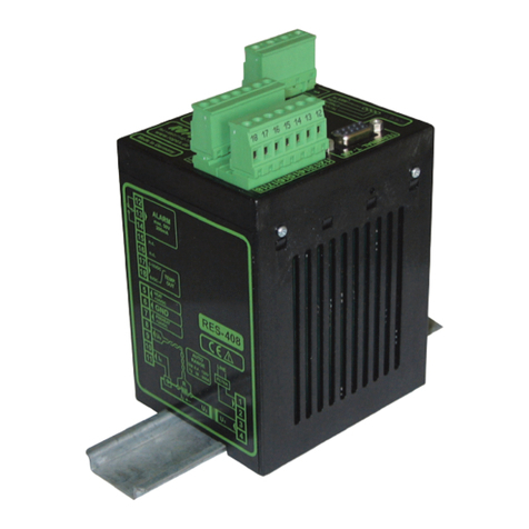
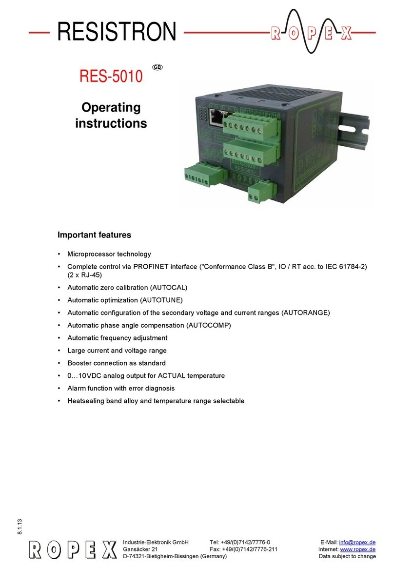
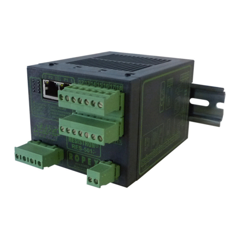
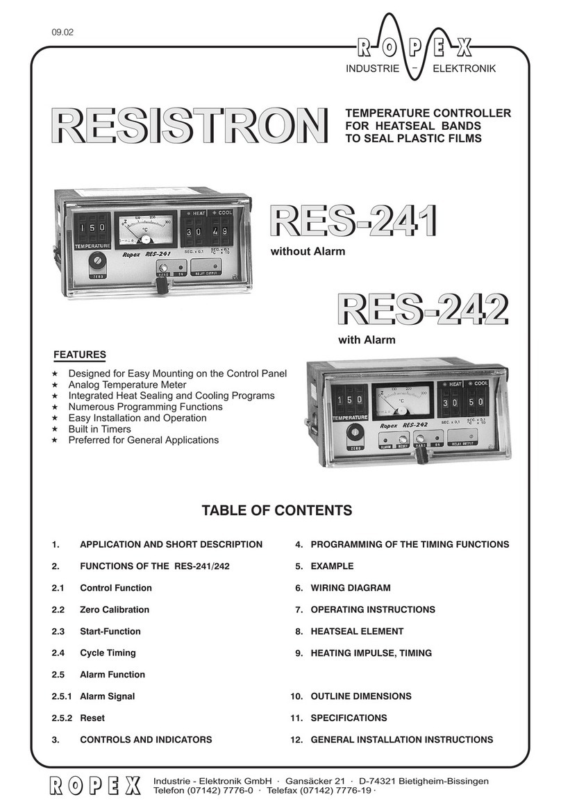
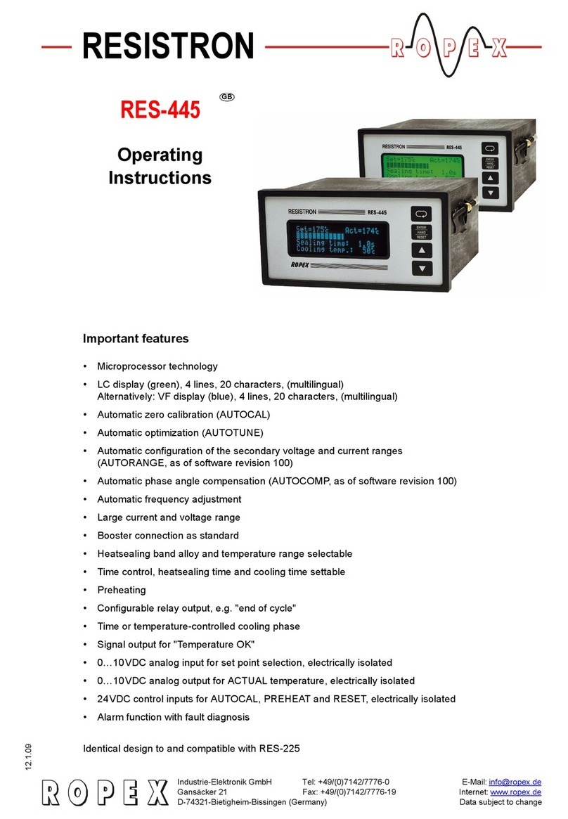
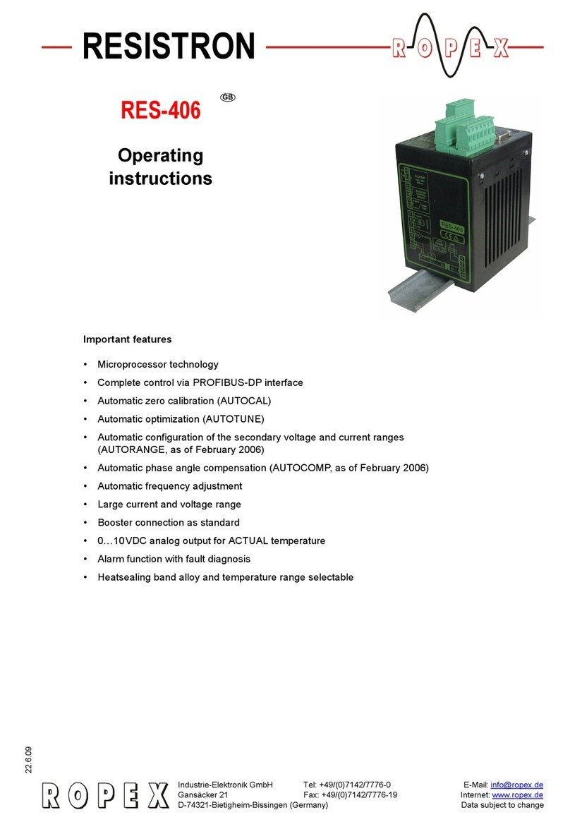
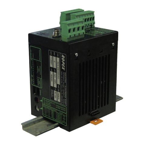
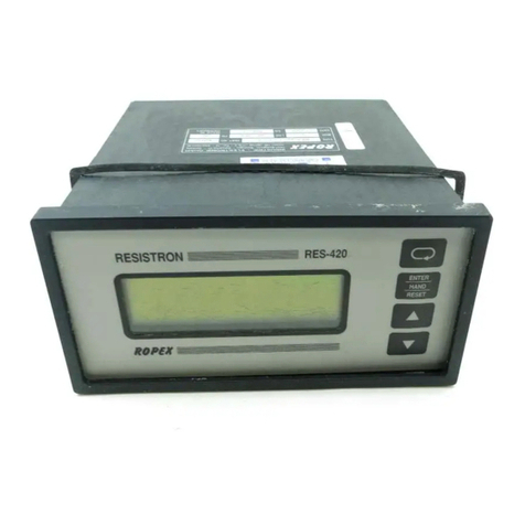
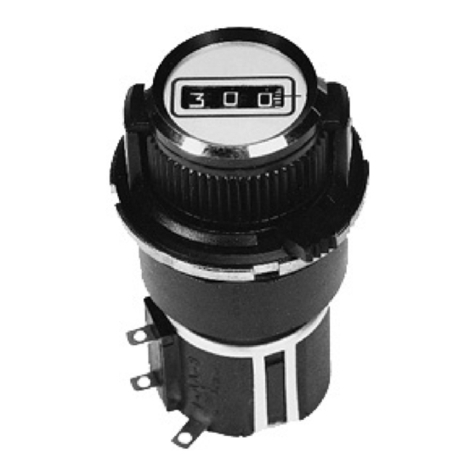
Ropex RESISTRON RES-5009 User manual

Adolf-Heim-Str. 4 Fax: +49 (0)7142-7776-211 Internet: https://ropex.de
74321 Bietigheim-Bissingen (Germany) Data subject to change
04.03.2021 Version 1
RESISTRON
RES-5009
Important features
• CAN interface CAN 2.0A as per ISO 11898 for complete regulator control
• CANopen®1 Protocol (as per CiA®1 profile 301 in version 4.2.0)
• ROPEX CAN protocol
• Automatic zero calibration (AUTOCAL)
• Automatic optimisation (AUTOTUNE)
• Automatic configuration of the secondary voltage and current range (AUTORANGE)
• Automatic phase correction (AUTOCOMP)
• Automatic frequency adaptation
• Booster output standard
• Analogue output 0…10 VDC for ACTUAL temperature
• Additional 24 VDC control signals for START 0 (setpoint 0) and START 1 (setpoint 1)
• Alarm function with error diagnosis
• Heating element alloy and temperature range can be selected
• Wide voltage range for the use of 110…480 V
• Eight channels for administration of various calibration values
• Micro-USB interface for ROPEXvisual®
• cULus approval
1. CiA® and CANopen® are European Union trade marks of CiA e.V.
User Guide

Page 2 RES-5009 Version 1
Contents
1 Revision list . . . . . . . . . . . . . . . . . . . . . . . . . 5
2 General information . . . . . . . . . . . . . . . . . . 5
2.1 Use of the operating instructions . . . . . 5
2.2 Drawings and illustrations . . . . . . . . . . 5
2.3 Copyright . . . . . . . . . . . . . . . . . . . . . . . 5
3 Safety . . . . . . . . . . . . . . . . . . . . . . . . . . . . . . 5
3.1 Warning notices in the operating
instructions . . . . . . . . . . . . . . . . . . . . . 5
3.2 General safety information . . . . . . . . . 7
3.3 Intended Use . . . . . . . . . . . . . . . . . . . . 7
3.4 User qualifications . . . . . . . . . . . . . . . . 7
3.5 DECLARATION OF CONFORMITY . . 8
4 Requirements for the functioning of the con-
trol system . . . . . . . . . . . . . . . . . . . . . . . . . . 9
4.1 Heating element . . . . . . . . . . . . . . . . . 9
4.2 Impulse transformer . . . . . . . . . . . . . 10
4.3 Current transformer . . . . . . . . . . . . . . 10
4.4 Line filter . . . . . . . . . . . . . . . . . . . . . . 10
4.5 Application report . . . . . . . . . . . . . . . 10
5 Product description . . . . . . . . . . . . . . . . . . 11
5.1 Use . . . . . . . . . . . . . . . . . . . . . . . . . . 11
5.2 Functional principle . . . . . . . . . . . . . . 12
5.3 Controller features . . . . . . . . . . . . . . . 12
6 Transport and Storage . . . . . . . . . . . . . . . 13
6.1 Scope of Delivery . . . . . . . . . . . . . . . 13
6.2 Transport and Storage . . . . . . . . . . . 13
7 Mounting and Installation . . . . . . . . . . . . . 13
7.1 Installation sequence . . . . . . . . . . . . . 13
7.2 Installation notes . . . . . . . . . . . . . . . . 15
7.3 Mains connection . . . . . . . . . . . . . . . 16
7.4 Line filter . . . . . . . . . . . . . . . . . . . . . . 17
7.5 Current transformer . . . . . . . . . . . . . . 17
7.6 Wiring diagram (standard) . . . . . . . . . 19
7.7 Wiring diagram with booster
connection . . . . . . . . . . . . . . . . . . . . . 20
8 Startup and operation . . . . . . . . . . . . . . . . 21
8.1 Device view . . . . . . . . . . . . . . . . . . . . 21
8.2 Device configuration . . . . . . . . . . . . . 21
8.3 Switch for activating the CAN terminating
resistor . . . . . . . . . . . . . . . . . . . . . . . . 24
8.4 Selection of CAN protocol . . . . . . . . . 24
8.5 Burning in and changing the heating
element . . . . . . . . . . . . . . . . . . . . . . . 25
8.6 Startup procedure . . . . . . . . . . . . . . . 26
9 Device functions . . . . . . . . . . . . . . . . . . . . 29
9.1 Display elements and operating
elements . . . . . . . . . . . . . . . . . . . . . . 29
9.2 Input data . . . . . . . . . . . . . . . . . . . . . . 30
9.3 Output data . . . . . . . . . . . . . . . . . . . . 34
9.4 Parameter data . . . . . . . . . . . . . . . . . 37
9.5 Undervoltage detection . . . . . . . . . . . 43
9.6 Temperature display (actual value
output) . . . . . . . . . . . . . . . . . . . . . . . . 44
9.7 Booster connection . . . . . . . . . . . . . . 45
9.8 USB interface for visualisation software
ROPEXvisual®. . . . . . . . . . . . . . . . . . 45
9.9 AUX interface . . . . . . . . . . . . . . . . . . 46
9.10 Total cycles counter . . . . . . . . . . . . . . 46
9.11 Operating hours counter . . . . . . . . . . 47
9.12 Data storage for error messages and
AUTOCAL . . . . . . . . . . . . . . . . . . . . . 47
9.13 Integrated clock (date and time) . . . . 47
9.14 System monitoring/alarm output . . . . 48
9.15 Error messages . . . . . . . . . . . . . . . . . 49
9.16 Error ranges and causes . . . . . . . . . . 54
9.17 Measures in the event of an error . . . 55
Version 1 RES-5009 Page 3
10 CANopen . . . . . . . . . . . . . . . . . . . . . . . . . . 56
10.1 Electronic Data Sheet (EDS) . . . . . . . 56
10.2 Setting the baud rate . . . . . . . . . . . . . 56
10.3 Setting the CANopen node address . 58
10.4 LSS . . . . . . . . . . . . . . . . . . . . . . . . . . 59
10.5 CANopen® LEDs . . . . . . . . . . . . . . . 59
10.6 Heartbeat . . . . . . . . . . . . . . . . . . . . . . 60
10.7 Object directory . . . . . . . . . . . . . . . . . 61
10.8 PDO mapping . . . . . . . . . . . . . . . . . . 69
10.9 Emergency messages . . . . . . . . . . . . 70
10.10 Store and restore functionality . . . . . . 71
10.11 START command . . . . . . . . . . . . . . . 71
10.12 Heating time limit . . . . . . . . . . . . . . . . 71
10.13 Master AUTOCAL (MA) . . . . . . . . . . . 72
10.14 Temperature range and alloy . . . . . . 72
10.15 TCR calculator . . . . . . . . . . . . . . . . . . 72
10.16 Signals START 0 and START 1 . . . . 73
10.17 Date and time in CANopen . . . . . . . . 73
10.18 CANopen Time stamp object . . . . . . 74
10.19 CANopen states . . . . . . . . . . . . . . . . 74
10.20 Transmission of multi-byte elements with
CANopen . . . . . . . . . . . . . . . . . . . . . . 74
10.21 CANopen Timing values . . . . . . . . . . 74
11 ROPEX CAN . . . . . . . . . . . . . . . . . . . . . . . . 75
11.1 Setting the baud rate . . . . . . . . . . . . . 75
11.2 Setting the CAN identifier . . . . . . . . . 76
11.3 ROPEX CAN LEDs . . . . . . . . . . . . . . 76
11.4 ROPEX CAN protocol . . . . . . . . . . . . 77
11.5 Receiving CAN messages . . . . . . . . . 77
11.6 Sending CAN messages . . . . . . . . . . 83
11.7 Reading and setting the internal clock 89
12 Factory settings . . . . . . . . . . . . . . . . . . . . . 89
13 Maintenance . . . . . . . . . . . . . . . . . . . . . . . . 90
14 Disposal . . . . . . . . . . . . . . . . . . . . . . . . . . . 90
15 Technical data . . . . . . . . . . . . . . . . . . . . . . 91
16 Dimensions . . . . . . . . . . . . . . . . . . . . . . . . 93
17 Modifications (MODs) . . . . . . . . . . . . . . . . 94
18 How to order . . . . . . . . . . . . . . . . . . . . . . . . 95
19 Index . . . . . . . . . . . . . . . . . . . . . . . . . . . . . . 97

Page 4 RES-5009 Version 1

Revision list
Version 1 RES-5009 Page 5
1 Revision list
2 General information
This RESISTRON® Temperature Controller has been developed and manufactured as per EN 61010-1 and is
checked and monitored several times during manufacture as part of quality assurance. The device is leaving our
factory in perfect condition.
2.1 Use of the operating instructions
These operating instructions are part of the product and describe the installation, start-up, operation, trouble-
shooting and maintenance of the RESISTRON® Temperature Controller.
Please ready the operating instructions carefully before using the RESISTRON® Temperature Controller. Keep
the operating instructions safe, for future reference. Please ensure that the important information and the functions
are always available to the user in the vicinity of the RESISTRON® Temperature Controller.
In order to ensure safe operation, please observe the safety and warning information included in the operating
instructions.
2.2 Drawings and illustrations
The drawings and illustrations in these operating instructions are exemplary. Many details are presented in a sim-
plified manner.
2.3 Copyright
All contents, in particular texts, photographs and graphics, are protected by copyright. All rights, including to rep-
lication, publication, editing and translation, are reserved.
3 Safety
3.1 Warning notices in the operating instructions
These operating instructions contain warning notices if there is a risk of personal injury or property damage. The
signal words in the warning notices draw attention to the particular dangers and indicate the severity of the danger.
The warning notices contained in the operating instructions must be observed in order to ensure safe operation.
Version Modification
1 • Preparation of documentation

Safety
Page 6 RES-5009 Version 1
3.1.1 Meaning of the signal words
The following signal words indicate the risk of personal injury and property damage:
3.1.2 Structure of section-related warnings
Section-related warnings apply to a section, a course of action or a specific procedure. They don't just apply to
a specific act. The hazard symbols used indicate a general or specific hazard.
Section-related warnings are structured as follows:
3.1.3 Structure of embedded warnings
Embedded warnings refer to a specific part within a paragraph. These warning notices apply to information units
smaller than the section-related warning notices.
Embedded warnings are structured as follows:
SIGNAL WORD
Instructions to avoid a dangerous situation
3.1.4 Meaning of the hazard symbols
The hazard symbols in the warning notices have the following meanings:
Signal word Importance
Imminent danger
Consequence: Death or serious injuries
Possibly imminent danger
Consequence: Death or serious injuries
Possibly imminent danger
Consequence: Slight or minor injuries
Possibly imminent danger
Consequence: Damage to property
or environment
Hazard
symbol
SIGNAL WORD
Type of danger and possible consequences
Measures to avert the danger
Warning of a danger point or dangerous situation
Warning of electrical voltage
DANGER
WARNING
CAUTION
ATTENTION

Safety
Version 1 RES-5009 Page 7
3.1.5 Information code
The following symbol indicates important information:
3.2 General safety information
3.3 Intended Use
RESISTRON® Temperature Controllers may be used only for heating and temperature control of heating elements
that are expressly suitable for this purpose, in compliance with the regulations, notes and warnings listed in these
instructions.
3.4 User qualifications
Only qualified specialists are allowed to carry out work such as assembly, installation, start-up and operation as
well as troubleshooting and maintenance of the RESISTRON® Temperature Controller. Qualified specialists are
persons who have been instructed in electrical engineering and who have the minimum qualifications required for
their work. These persons are familiar with the dangers and the guarantee provisions and they have read and
understood the operating instructions.
important information on the correct handling of the product
WARNING
Danger to life and danger of serious physical injuries as well as property damage if all warnings,
regulations and information are not followed.
Strictly follow all warnings, regulations and information in these operating instructions!
WARNING
Danger to life and risk of serious physical injuries as well as property damage if the work is not
carried out in a professional and professional manner.
Installation, electrical connection, start-up and maintenance of the RESISTRON® Temperature
Controller may be carried out only by qualified, trained personnel in accordance with these
operating instructions. Unauthorized and improperly carried out work during installation and
reconstruction, electrical connection, start-up and maintenance is prohibited for safety reasons!
NOTE
In case of non-compliance or improper use, there is a risk of impairment of safety or
overheating of heating elements, electrical lines, transformers, etc. This is the user's own
responsibility.

Safety
Page 8 RES-5009 Version 1
3.5 DECLARATION OF CONFORMITY
We hereby declare that the following device has been developed and manufactured in conformance with the direc-
tives cited below:
Compliant with following standards and directives:
Note:
This declaration of conformity certifies that the device/electronic itself complies with the above-mentioned direc-
tives. The CE mark on the device/electronic does not relieve the machinery manufacturer of his duty to verify the
conformity of the completely installed, wired and operationally ready system in the machine with the EMC directive.
Comments:
RESISTRON/CIRUS temperature controllers are not independently operable devices. They are used by the
machinery manufacturer to form a sealing system by adding EMC-relevant components such as filters, trans-
formers, heatsealing bands and wiring. The final configuration may vary significantly in terms of performance and
physical dimensions. All information provided by us in connection with the line filter is merely intended as a guide
and is based on a typical measuring setup. It serves to demonstrate that compliance with the EMC directive can
be achieved by using a line filter that is suitable for the overall system. The line filter and current transformer must,
however, be determined on the basis of the respective application. We also wish to point out that the transformer
which is used must be designed in accordance with VDE 0551/EN 61558 or UL 5058 for safety reasons.
ROPEX Industrie-Elektronik GmbH
Adolf-Heim-Str. 4
74321 Bietigheim-Bissingen (Germany)
Designation: RESISTRON/CIRUS temperature controller with accessories
Type: With line filter and current transformer
Operating principle: Impulse sealing of films and plastics
EN 61010-1 Safety requirements for electrical equipment, control, and laboratory use
2014/35/EU Low voltage directive
2014/30/EU Electromagnetic compatibility directive
2011/65/EU RoHS directive
July 12, 2020
J. Kühner (CEO)

Requirements for the functioning of the control system
Version 1 RES-5009 Page 9
4 Requirements for the functioning of the control system
4.1 Heating element
The resistance of the heating element used must have a positive temperature coefficient for the proper functioning
of the RESISTRON® Temperature Controller.
In order to achieve an optimal sealing result, the heating element and the type of connection must be adapted to
the sealing application. The geometry of the heating element cannot be discussed here due to its diversity.
Accordingly, only some important physical and electrical characteristics are pointed out here:
The measurement principle used here requires a suitable temperature coefficient TCR from the heating element
alloy. The RESISTRON® Temperature Controller is suitable for temperature coefficients in the range
400…4000 ppm/K.
As the heating element heats up, the resistance value increases, through which the control is made possible. If
the temperature coefficient of the heating element is below the range, the control circuit oscillates or the heating
element overheats.
The temperature coefficient must be given as follows:
E.g. Alloy A20: TCR = 1100 ppm/K
Alloy L: TCR = 780 ppm/K
LEX3500: TCR = 3500 ppm/K
Vacodil: TCR = 1100 ppm/K
The setting or coding of the RESISTRON® Temperature Controller has to be carried out according to the temper-
ature coefficient of the heating element used.
The temperature coefficient must be taken from the ROPEX application report and must be set accordingly.
More information:
• High-resistance heating elements, such as NiCr 80/20, are not suitable for an operation with a RESISTRON®
Temperature Controller.
•Parallel wiring: In order to achieve an uniform temperature of both the heating elements, symmetrical cabling
must be taken into account in case of parallel wiring of heating elements.
•Series wiring: When heating elements are connected in series, it must be ensured that the heating elements
do not touch each other when they are heated on both sides. This would lead to an overcurrent and conse-
quently to a selective increase in temperature.
NOTE
If the temperature coefficient of the heating element is greater than the set value, the real tem-
perature is lower than the displayed temperature. However, if the temperature coefficient of
the heating element is greater than the set value, the real temperature is higher than the dis-
played temperature.
WARNING
The use of the wrong alloys with a temperature coefficient, which is too low, or the wrong coding
of the RESISTRON® Temperature Controller leads to uncontrolled heating and possibly to
the burning up of the heating element!
TCR 10x10 4– K1– or K 1– or ppm/K=

Requirements for the functioning of the control system
Page 10 RES-5009 Version 1
• A very important design measure is copper-coating or silver-coating of the heating element ends. The thermal
characteristics change in this range through coating of the heating element ends. As a result, the ends remain
cold, which permits exact temperature control and increases the useful life of the heating element and the wear
materials (e.g. silicone underlayment, heating band cover).
4.2 Impulse transformer
A suitable impulse transformer is required for the control loop to function properly. The power and the secondary
voltage must be laid out for the control loop. According to EN 61558 or UL 5058, the transformer must be laid out
as an isolating transformer with reinforced insulation and have a single-chamber structure. Adequate protection
against accidental contact must be provided when assembling the impulse transformer. The relevant national
installation and construction regulations must be observed, while doing so. Water, cleaning solutions and / or con-
ductive liquids may not come into contact with the impulse transformer.
The cable cross-sections must be designed as per the ROPEX application report.
Incorrect assembly and installation of the impulse transformer impair electrical safety.
The terminals on the pulse transformer must be checked and tightened regularly.
4.3 Current transformer
The current transformer appropriate for RESISTRON® Temperature Controller is part of the control system.
In order to avoid malfunctions, only the original ROPEX current transformers or ROPEX monitoring current trans-
formers may be used.
The current transformer may be operated only if it is correctly connected to the RESISTRON® Temperature Con-
troller (See Chapter “Start-up”). The safety-related information in the “Mains connection” chapter must be
observed. External monitoring modules can be used to increase operational safety furthermore. Monitoring mod-
ules are not part of the standard control system and are described in separate documentation.
4.4 Line filter
ROPEX offers line filters in various performance classes. The ROPEX Application Report lists the suitable line
filter, which can be ordered.
For fulfilling the guidelines mentioned in the section 1.5 "DECLARATION OF CONFORMITY" on page 6, it has
been stipulated to use an original ROPEX line filter. Installation and connection must be carried out in accordance
with the instructions in the "Mains connection" chapter or the separate documentation for the respective line filter.
4.5 Application report
The ROPEX application report contains all the important technical information on your sealing applications. If you
have several applications in a system, these are displayed in the application report on different pages and col-
umns. This allows you to easily differentiate between them. The application report is created individually by
the ROPEX application team and is the basis for the electro-technical design of your sealing applications.
The ROPEX application report contains the following information among other things:
• List of the different heating element dimensions
• Specification of the necessary temperature coefficient

Product description
Version 1 RES-5009 Page 11
• Electro-technical data as the basis for the electrical components
• Parts list and schematic diagram for the necessary components
• Instructions and recommendations for mechanical design
• Instructions for installing the cables and components
To receive a ROPEX application report, please fill out our questionnaire completely. When you send the completed
questionnaire, a new window opens with a reference number (e.g. AR1234) and a link to the questionnaire you
created. This link enables you to reopen the questionnaire for your next inquiry. We therefore recommend that you
save the link and the reference number.
Subsequently, you will have the opportunity to send us further information on this questionnaire, such as for
example, technical descriptions or pictures.
The ROPEX application team then creates the application report based on the data you have entered. If relevant
data is missing, we will contact you to clarify the open points. As soon as the application report has been created,
you will receive it by email. We will then send you an offer for the components listed in the application report.
If you cannot judge whether your material can be sealed or what cycle rate is possible, we can also create sealing
samples for you. We will then use our system and your material to check the possibility for sealing and incorporate
the findings into the application report.
In this case you are welcome to contact [email protected]. Your request will then be passed on to the application
team to coordinate the next steps.
5 Product description
5.1 Use
This RESISTRON® Temperature Controller RES-5009 is part of “Series 5000” with microprocessor technology as
its main characteristic. All RESISTRON® Temperature Controller are used for controlling the temperature of
heating elements. Heating elements are used in a wide variety of film sealing processes.
The most common heating elements include:
• ribbon cables (straight and contoured)
• tapered bands
• beaded bands
• cutting wires (straight and contoured)
• heated sealing and cutting knives
• soldering bows
The main application area is sealing or cutting of thermoplastics using the thermal impulse process.
The most common application areas are:
• vertical and horizontal flow wrapping machines (VFFS and HFFS)
• bagging, filling and sealing machines
• film-wrapping machines
• bag-production machines
• group packaging machines
• film welding devices
• spout and tube sealing
• and much more.

Product description
Page 12 RES-5009 Version 1
5.2 Functional principle
The resistance of the heating element, which changes with temperature, is measured by means of current and
voltage measurement, displayed and compared with the specified setpoint value. Measurements are made 50
times per second in a 50 Hz line, 60 times per second in a 60 Hz line.
The primary voltage of the impulse transformer is adjusted following the leading edge principle if the measured
values deviate from the setpoint value. The related current change in the heating element results in a rise in tem-
perature and change of resistance. This change in resistance measured and evaluated by the RESISTRON® Tem-
perature Controller RES-5009. The temperature controller adjusts the control variables according to the change
and the established setpoint.
Even the smallest thermal loads on the heating element are recorded and can be quickly and precisely corrected.
Measurement of pure electric variables, together with the high measurement rate, result in a highly dynamic ther-
moelectric control circuit. The principle of primary-side transformer control proves to be especially advantageous
as it permits a very large secondary current range with low power loss. This permits an optimal adjustment to the
load and thus the desired dynamics with extremely compact device measurements.
5.3 Controller features
The RESISTRON® Temperature Controller RES-5009 is equipped with a CAN interface. Through this CAN inter-
face, all functions and parameters can be parameterised by means of the higher level machine controller. In addi-
tion, important controller information is queried and can be processed accordingly. CANopen and the
ROPEX CAN protocol are supported.
The ACTUAL temperature of the heating element is output through the CAN interface and through an analogue
output 0…10 VDC. The real heating element temperature can be visualised on an external display instrument
(e. g. ATR-x) or via the operating unit of the machine controller.
The RESISTRON® Temperature Controller RES-5009 has an integrated error diagnosis, which checks both the
external system (heating element, wiring, etc.) and the internal electronics. A differentiated error message is
output through the CAN interface in case of a fault.
To increase operational security and immunity to interference, all CAN signals from the controller and heating cir-
cuit are electrically isolated.
Adjustment for different heating element alloys (alloy A20, Vacodil, etc.) and setting of the temperature range to
be used (0…300 °C or 0…500 °C) can be made through coding switches on the temperature controller itself or
through the CAN interface.
The compact design of the RESISTRON® Temperature Controller RES-5009 as well as the plug-in connecting
terminals make mounting and installation easier.
An overview of the most important features and functions:
• AUTOCAL - Easy calibration of the heating element by automatic zero-point setting.
• Eight channels permit switching of the calibration parameters during tool change.
• AUTOTUNE - high control dynamics by automatic adaptation to the control path.
• AUTORANGE - automatic configuration of the secondary voltage range and current range, high flexibility due
to the coverage of a secondary voltage range from 0.4 V to 120 V and a current range from 30 A to 500 A.
• Automatic adjustment to the line frequency in the range of 47 Hz to 63 Hz.
• Wide voltage range for flexible use from 110 VAC to 480 VAC
• Easy and convenient system diagnosis and process visualisation through the free, downloadable software
ROPEXvisual®
• Comprehensive error diagnosis over the CAN interface
• Booster output available for connecting a switching amplifier

Transport and Storage
Version 1 RES-5009 Page 13
• High process security through comprehensive options for evaluating the parameter data (e. g. temperature
diagnosis or heat-up time monitoring)
6 Transport and Storage
6.1 Scope of Delivery
After receipt of the delivery, immediately check the completeness of the scope of delivery on the basis of the
accompanying documents.
After receipt of the delivery, perform a visual inspection for possible damage.
6.2 Transport and Storage
Transport and store the device in its original box. For the ambient conditions, please refer to the technical data
(section 15 "Technical data" on page 91). After a longer period of storage of the RESISTRON® Temperature
Controller RES-5009, ROPEX Industrie-Elektronik GmbH will handle the functionality testing for a fee.
7 Mounting and Installation
See also section 4 "Requirements for the functioning of the control system" on page 9.
7.1 Installation sequence
Proceed as follows during mounting and installation of the RESISTRON® Temperature Controller RES-5009:
1. Switch off line voltage and 24 VDC power supply; verify lack of voltage.
2. Installation of the RESISTRON® Temperature Controller in the switching cabinet on a TS35 top-hat rail (in
accordance with EN 60715). If several devices are mounted, the minimum distance specified in section 15
"Technical data" on page 91 must be maintained.
NOTE
ROPEX Industrie-Elektronik GmbH does not assume any guarantee for defects that are sub-
sequently claimed.
WARNING
The assembly, installation and startup may be performed only by technically trained and com-
petent persons. The persons must be familiar with the associated dangers and guarantee pro-
visions.
CAUTION
The supply voltage to the machine side must lie within the permitted voltage and frequency
range of the temperature controller. Otherwise, there is the danger of a defect.

Mounting and Installation
Page 14 RES-5009 Version 1
3. Wiring of the system in accordance with the regulations in section 7.3 "Mains connection" on page 16,
section 7.6 "Wiring diagram (standard)" on page 19 and the ROPEX application report. The specifications in
section 7.2 "Installation notes" on page 15 must also be observed.
Cables that are connected to control or measurement connections may only run within the building.
4. During installation, a circuit breaker with max. 10 A must be provided, e. g.:
- circuit breaker in accordance with EN 60898 (characteristic B, C, D, K or Z)
- circuit breaker in accordance with UL489 (*) (characteristic B, C, D, K or Z)
- protective fuse gG in accordance with IEC 60269
- protective fuse “Class CC” or “Class J” in accordance with UL 248 (*)
The circuit breakers marked with (*) must be used in installations falling under the UL regulations.
If the specified circuit breaker is not sufficient for the welding application, two separate circuit breakers must be
provided for the controller and the welding application (ROPEX application report).
The circuit breaker must be located in the immediate vicinity of the device.
In the ROPEX application report, the smallest possible specification for this circuit breaker is specified based
on the calculated currents. If the protective device is dimensioned differently, the current carrying capacity of
the components used (e. g. cable, impulse transformer, etc.) must be adjusted accordingly.
5. A disconnect device must be provided during installation. The disconnect device must be properly marked as
part of the system and attached in an easily accessible position.
If a circuit breaker is used, it can take over the function of the disconnect device.
6. Connect the RESISTRON® Temperature Controller RES-5009 to the CAN network with a SUB-D9 connection
cable according to specification CANopen CiA 303/1.
CAUTION
Check all connection terminals of the system and the terminals for the coil wires on the impulse
transformer – that they are seated firmly.
7. Check the wiring in accordance with the applicable national and international installation and setup require-
ments.

Mounting and Installation
Version 1 RES-5009 Page 15
7.2 Installation notes
NOTE
The correct dimensioning of the system components is crucial for the correct functioning of the
control loop. Please take this data from the ROPEX application report.
NOTE
In order to enable a good and stable control, additional resistances (fuses, long lines, plug con-
nections, ...) must be avoided in the secondary circuit.
Additional resistances influence the control and can make the system prone to errors, in the
long term.
Line
Impulse
transformer
Current transformer
PEX-W4 / W5
U (prim.)
1
Heatsealing band R= f (T)
U (sec.)
2
A
F
Avoid long
cables
Heatseal element
with coppered ends
Use heatseal bands with
suitable temperature coefficient
20 mm clearance if several
controllers installed on
one top hat rail
No additional
resistance
in secondary
circuit
Dimension
transformer correctly
- Secondary voltage
- Power
- Duty cycle
Sufficient wire
cross-section
No
push-on
connectors
Twisted
Current measuring
wires IR
R
Connect U measuring
wires directly to
heatsealing band ends
Line filter
LF-xxxxx
Note
number
of turns

Mounting and Installation
Page 16 RES-5009 Version 1
7.3 Mains connection
Line
To avoid disturbances while measuring, place several con-
trol loops on the same phase if possible.
Overcurrent device
2-Pole circuit breaker or fuses,
(ROPEX application report).
ATTENTION - protection only in the event of
a short circuit.
No protection of the RESISTRON®
Temperature Controller.
Contactor Ka
For all-pole disconnection, EMERGENCY OFF or EMER-
GENCY STOP.
Dimensioning ROPEX application report
Line filter
Filter type and filter size must be based on load, trans-
former and machine cabling (ROPEX application
report).
CAUTION Do not lay filter supply lines (mains
side) parallel to filter output lines (load side).
RESISTRON® Temperature Controller
Contactor Kb
CAUTION To increase machine safety by
switching off the load on all poles in the event
of a fault, e.g. in combination with the ALARM
output of the RESISTRON® Temperature Controller.
Dimensioning ROPEX application report I1max
(for Ka and Kb)
Impulsetransformer
Design according to EN 61558 or UL 5058 (isolating trans-
former with reinforced insulation). Ground core.
CAUTION Use only single-chamber design.
Power, ED number and voltage values must be
determined individually depending on
the application (ROPEX application report).
Wiring
Cable cross-sections depend on the application
(ROPEX application report).
Make sure to twist (min. 20 beats/meter,
Accessories “twisted measuring line”)
Twisting (min. 20 beats/meter) necessary if
several control loops are laid together
(“Crosstalk”).
Twisting (min. 20 beats/meter) recommended to
improve EMC properties.
ROPEX
temperature
controller
UR
IR
R
PRIM.
U1
Kb
Ka
SEC.
U2
LINE
I
>
I
>
GND/
Earth
N(L2)
L1 (L1)
LINE
FILTER
ON
OFF
Kc
3
3
3
1
Short wires
2
2

Mounting and Installation
Version 1 RES-5009 Page 17
7.4 Line filter
In order to comply with the EMC directive, RESISTRON control loops must be operated with earthed line filters.
The earthed line filters serve to attenuate the effect of the phase-anglecontrol on the line and to protect the con-
troller against line disturbances.
CAUTION
The use of a suitable line filter is part of compliance with the standards and a prerequisite for CE
marking.
ROPEX line filters are specially optimized for use in RESISTRON control loops and guarantee compliance with
the EMC limit values when installed and wired correctly. The specification of the line filter can be found in the
ROPEX-application report created for your sealing application.
Further technical information: Documentation “line filter”.
The supply of several control loops via a line filter is permitted if the total current does not exceed the maximum
current of the filter.
The instructions in the section 7.3 "Mains connection" on page 16 with regard to cabling must be complied with.
Example drawing for LF-06480:
7.5 Current transformer
The current transformer PEX-W4/-W5 appropriate for RESISTRON® Temperature Controller is part of the control
system. The current transformer may be operated only if it is correctly connected to the temperature controller
(section 7.3 "Mains connection" on page 16).
If several heating elements are operated with one control circuit, the installation can be found in the ROPEX appli-
cation report. In special applications with RESISTRON® Temperature Controller it is necessary that a short circuit
between the heating element and earth/housing is detected and the control system is switched off immediately.
The MSW-2 monitoring current transformer can be used for this.
Further technical information can be found in the separate documentation for the current transformer and moni-
toring current transformer.
LINE
PE
Large cross-section
wire to ground
Large cross-section
wire to ground
Large frame contact surface
Do not lay parallel Mounting plate (galvanized)
max. 1 m
ROPEX
temperature
controller

Mounting and Installation
Page 18 RES-5009 Version 1
7.5.1 PEX-W4
7.5.2 PEX-W5
The current transformer is mounted on a hat rail measuring 35 x 7.5 mm or 35 x 15 mm in accordance with
EN 60715.
If the high-current line cannot be conducted through the opening provided due to the diameter, an HCB-1 high-
current rail must be used.
Snap-on for DIN-rail 35 x 7,5mm or 35 x 15mm (EN 60715)
terminal
block
terminal
wires
14
60
24 75 14
23 28
26
39
12

Mounting and Installation
Version 1 RES-5009 Page 19
7.6 Wiring diagram (standard)
RES-5009
9
8
7
6
5
4
3
2
1
7
CAN Bus plug
SUB-D / 9-pole
5
CAN Bus
Controller
electricaly
isolated
+24 VDC
GND
NC
NC
CAN_GND
CAN_SHLD
NC
CAN_GND
NC
SUPPLY
CAN_H
CAN_L
R
Current
transformer
Impulse
transformer
LINE
11
9
10
8
4
3
2
1
IR
UR
15
Heatsealing
element
sec.
U2
prim.
U1
twisted
Line filter
ALARM OUTPUT
max. 30 V
Ground
Must be grounded
externally to
prevent electro-
static charging!
17
°C
ATR
_
+
ANALOG OUTPUT
+0...10 VDC
14
13
12
6
Shield
START 1 (Setpoint 1)
with 24 VDC signal
START 0 (Setpoint 0)
with 24 VDC signal 716
18
BOOSTER
OUTPUT

Mounting and Installation
Page 20 RES-5009 Version 1
7.7 Wiring diagram with booster connection
RES-5009
9
8
7
6
5
4
3
2
1
7
CAN Bus plug
SUB-D / 9-pole
5
CAN Bus
Controller
electrically
isolated
+24 VDC
GND
NC
NC
CAN_GND
CAN_SHLD
NC
CAN_GND
NC
SUPPLY
CAN_H
CAN_L
R
Current
transformer
Impulse
transformer
LINE
11
9
10
8
4
3
2
1
IR
UR
15
Heatsealing
element
sec.
U2
prim.
U1
twisted
Booster
24
IN OUT
13
Line filter
twisted
Length: max. 1 m
NC
NC
ALARM OUTPUT
max. 30 V
Ground
Must be grounded
externally to
prevent electro-
static charging!
17
°C
ATR
_
+
ANALOG OUTPUT
+0...10 VDC
14
13
12
6
Shield
START 1 (Setpoint 1)
with 24 VDC signal
START 0 (Setpoint 0)
with 24 VDC signal 716
18
7
Table of contents
Other Ropex Controllers manuals

Ropex
Ropex Resistron RES-5011 User manual

Ropex
Ropex RESISTRON RES-409 User manual

Ropex
Ropex RESISTRON RES-408 User manual

Ropex
Ropex RESISTRON RES-409 User manual

Ropex
Ropex RES-225 User manual

Ropex
Ropex Resistron RES-430 Series User manual

Ropex
Ropex Resistron RES-242 User manual

Ropex
Ropex CIRUS UPT-6010 User manual

Ropex
Ropex RESISTRON RES-406 User manual

Ropex
Ropex Resistron RES-220 Quick start guide