Ropox FlexiPlus User manual

TF 200.01.0020_ENG
Ropox Flexi+
User manual
This manual should always be in close proximity to the
product
TF 200.01.0020 / Date 04-10-2021

Page | 2
TF 200.01.0020_ENG
Table of Contents
1. Symbols used in this manual............................................................................................................. 3
2. General safety..................................................................................................................................... 3
2.1 Product Unit label.................................................................................................................. 5
3. General requirements......................................................................................................................... 6
3.1 Product information............................................................................................................... 6
3.2 Product description............................................................................................................... 6
3.3 Intended use......................................................................................................................... 6
3.4 Intended population .............................................................................................................. 6
3.5 Intended operator.................................................................................................................. 6
3.6 Basic safety.......................................................................................................................... 6
3.7 Non-clinical functions............................................................................................................ 6
3.8 Product dimensions .............................................................................................................. 7
3.9 Complaints and adverse events ............................................................................................ 7
4. Instructions for use............................................................................................................................. 8
4.1 Installation of product............................................................................................................ 8
4.2 Installation of countertop......................................................................................................12
4.3 Electrical component diagram..............................................................................................13
4.4 Operating the product ..........................................................................................................13
5. Accessories .......................................................................................................................................14
5.1 Installation of accessories....................................................................................................14
6. Troubleshooting.................................................................................................................................20
7. Cleaning .............................................................................................................................................20
8. Maintenance.......................................................................................................................................20
8.1 Periodic maintenance...........................................................................................................20
8.2 Calibration of actuator..........................................................................................................20
9. Component part list...........................................................................................................................21
10. Spare parts list...................................................................................................................................24
11. Environmental protection..................................................................................................................25
12. Electromagnetic compatibility...........................................................................................................25
12.1 Suitable Environments .....................................................................................................25
12.2 Adjacent and stacked use................................................................................................25
12.3 Cables .............................................................................................................................25
12.4 RF portable equipment.....................................................................................................26
12.5 Compliance for emission and immunity standard..............................................................26
Page | 3
TF 200.01.0020_ENG
1. Symbols used in this manual
Warning Symbol
Indication of potentially hazardous situation. If not avoided, it can
result in serious injury or death.
Caution Symbol
Indication of potentially hazardous situation which may result in
minor or moderate injury.
It may also be used to alert against unsafe practices.
Notice Symbol
This symbol is used to notify correct use and handling of the
product.
2. General safety
This manual must be read and understood before use.
Always keep this manual in close proximity of the product.
The use, installation and service of this product must follow
this manual to avoid accidents and serious personal injury.
Never use or handle this product in other ways specified in
this manual as it can result in personal safety hazards and/or
cause damage to the product.
Anyone installing and/or using this product either as operator
or user should have the necessary safety information and
access to this manual.
If the supply cord is damaged, it must be replaced by the
manufacturer, its service agent, or similarly qualified
designated person to avoid a hazard.

Page | 4
TF 200.01.0020_ENG
Do not perform repairs, disassembly, or assembly operations,
add-ons, re-adjustments, or modification of the product
beyond what is described in this manual. These must be
carried out by Ropox or Ropox authorized personnel. Do not
perform service while in use.
This appliance can be used by children aged from 8 years
and above and people with reduced physical, sensory, or
mental capabilities, or lack of experience and knowledge if
they have been given supervision, or instruction concerning
use of the appliance in a safe way and understand the
hazards involved. Children shall not play with the appliance.
Cleaning and user maintenance shall not be made by
children without supervision.
Do not use the product if it has defects or has become
damaged before being repaired or replaced.
If the control box makes unusual noise, or smells, switch off
the mains voltage immediately.
Take care that the cables are not damaged.
Unplug the mains cable on mobile equipment before it is
moved.
The products must only be used in an environment that
corresponds to their IP protection.
The information in this manual is based on correct installation
in accordance with installation instructions for this product.
Ropox cannot be held liable if the product is used in any way,
that differs from stated in this manual and/or installation
instruction.
Ropox reserve the right to amend this manual and reference
documents without prior notice.

Page | 5
TF 200.01.0020_ENG
2.1 Product Unit label
This product is CE-marked in accordance with:
Council Directive 2006/42/EC on machinery
Council Directive 2011/65/EU, RoHS
Manufacturer name and address
Date of production
Stock number
Serial number
Consult manual before use
Operating interval of electrically operated equipment. The use of electrical
height adjustable equipment can run at maximum 1 minute, followed by a 9
minute break.
Consult manual for important safety related information, warnings, and
safety precautions.
Do not dispose as unsorted municipal waste. Product must be returned to a
designated recycling station.
Operating temperatures may not exceed +10°C - +40°C
Transport and storage temperatures may not exceed -10°C - +50°C

Page | 6
TF 200.01.0020_ENG
3. General requirements
3.1 Product information
Manufacturer
Ropox A/S
Ringstedgade 221, DK-4700 Naestved
+45 55 75 05 00
Email: Info@ropox.com
Product models
Part number
Model
Configuration
30-90xxx-x
60 –300 cm
Electrical
Maximum user weight
according to DS/EN 12182:2012
150kg evenly distributed
max load includes weight of tabletop and other installations
Power supply
100-240V ~50/60Hz
I in
3A
Standby power
0,1 W
Intermittence
1min use / 9min break
Height adjustment
300mm
Speed of actuation
≈36mm/s
IP rating
IPX20
Ambient temperature range
-10 °C to +50 °C Transport and storage
+10 °C to +40 °C Operation
3.2 Product description
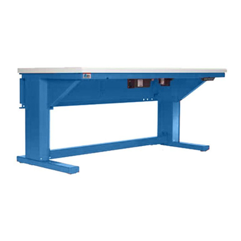
Ropox Flexi+ is a height-adjustable system for tabletops or workstations. The product can be
adjusted in height electrically.
3.3 Intended use
The product is intended for height adjustment of a tabletop or workstation for easier and more
comfortable use by people with differing heights and statures. Standard stroke length –300mm,
but with an option to customize stroke length between 0mm - 660mm.
3.4 Intended population
Anyone who can find use in having a tabletop or workstation with an adjustable height.
3.5 Intended operator
Anyone who has read and understood this manual can use the product. Only children over the age
of 8 may use the product, however, only under the supervision of an adult.
3.6 Basic safety
Ropox Flexi+ has a built-in anti-collision system called Ropox Sicuro, where, if the product
registers an increase in resistance during operation, either up or down, the legs will retract (approx.
50mm).
Additionally, it’s possible to buy what’s called a safety-stop. This is a safety system that works in
tandem with Ropox Sicuro, that is especially sensitive and is better at registering soft material. The
safety-stop is placed underneath the table, at the edge, which makes it optimal for seated users.
3.7 Non-clinical functions
Ropox Flexi+ is designed to make use of tabletops and worktops comfortable and easier to access
for the intended population.

Page | 7
TF 200.01.0020_ENG
3.8 Product dimensions
Aluminum profile is always 50mm shorter than tabletop.
60 –244cm
245 –300cm
3.9 Complaints and adverse events
Any serious incident that has occurred in relation to the use of the product, should be reported to
the manufacturer and the competent authority of the Member State in which the user is located.

Page | 8
TF 200.01.0020_ENG
4. Instructions for use
4.1 Installation of product
Check that there is 50mm free space above the floor, so the legs can be attached directly to the wall.
2-3

Page | 9
TF 200.01.0020_ENG
4.1.1A
Mark these two points for leg installation
Keep a minimum distance of 8cm to fixed
objects next to tabletop.
Be aware of countertop overhang.
4.1.1B
Attach wall brackets the points marked
out
If needed use rawlplugs. Max pull-out force in
top screw is 30kg.
4.1.1C
Plumb the wall brackets and attach top
screws
4.1.1D
Slide motor columns in wall brackets

Page | 10
TF 200.01.0020_ENG
4.1.2A
Mount support arms on profile
Do note, that the support arms must not be
more than 60cm apart. Also note that the
outermost support arms must face inwards
with their outer bracket. This is done by
unscrewing the bracket.
4.1.2B
Mount the spacer on the profile in each
end
Tighten the bottom screws to fasten the
spacer.
4.1.2C
Mount the adjustment screws on the leg,
in line with where the support arm will be
placed
4.1.2D
Mount the profile on the motor columns

Page | 11
TF 200.01.0020_ENG
4.1.2E
Level out the system by adjusting the nut
at the bottom of each motor column
4.1.2F
Lock the system by securing the retainer
nut at the bottom of each motor column
4.1.2G
Attach the control box to the profile
4.1.2H
Connect cables to the control box and do
a test run
Zero out the system by holding the down
button until the columns have initiated a
reset.

Page | 12
TF 200.01.0020_ENG
4.2 Installation of countertop
4.2.1A
Place countertop and secure it to the
support arms
Keep a safe distance of 5mm to the wall.
4.2.1B
Attach front fascia and side fascia if
needed
Before mounting side fascia, mount the angle
fittings.
4.2.1C
Level the system by adjusting the
adjustment screw and set screw on each
leg by means of a hex key

TF 200.01.0020_ENG
Page | 13
4.2.1D
Mounting the press pad
•Drill a Ø12-15 hole in the front fascia
•Pull cable through hole in front fascia and connect the press pad, via the press pad cable, to the
control box
•Carefully remove the protection paper, on the back of the press pad, while keeping your finger
between the cable-ribbon and the adhesive, as these mustn’t stick to each other
•Place the press pad on the front fascia
4.3 Electrical component diagram
4.4 Operating the product
The product is operated with the up / down button provided. Alternatively, if a control with lock function is
installed, see 5.1.3.
Warning!
The product should always be able to travel the full range of actuation without colliding
with objects. Failing to do so will compromise the product stability.
Special care should be taken in ensuring that no children or adults are placed under the
product, as severe injury from entrapment may occur.
Notice!
If the cable-ribbon sticks to the adhesive, the press pad might be destroyed.
Motor cable
Motor cable
Power
Cable for press
pad/control with
lock function

TF 200.01.0020_ENG
Page | 14
Page | 14
5. Accessories
Accessories
Item Number
30-92xxx
93000213
30-90540-1
30-67610-1
30-67635
30-67760
30-67705
30-90530
30-93050 –30-93660
Model/specification
Safety strip
Control with lock function
Wireless control incl. bluetooth adapter
Extra leg
Cover for plumbing
Bracket for coverplates
Supporting Foot 49cm Length
70mm distance bracket
Height adjustable programming, 50 –660mm
5.1 Installation of accessories
5.1.1 Installation of safety strip
•Insert SLS cable between leg and control box. It is recommended to use one of the
outer legs
•Connect minijack cable with SLS cable
•Connect safety strip with cable
•Mount the safety strip on the bottom side of the fascia by means of the double adhesive
tape starting at the furthest point from the control box
•Finish safety strip 1 cm from edge and push end resistance into the safety strip

Page | 15
TF 200.01.0020_ENG
5.1.2 Installation of control with lock function
•BEFORE MOUNTING THE FRONT FASCIA, pre-drill holes in the tabletop.
•Mount the control with lock function on the bottom side of the table, by means of two Ø
4.5mm countersink screws. It is recommended that the tilted part of the control is outside
the fascia, as shown below.
•Connect the control to the control box.
•If a fascia is needed, cut out a small indent in the front fascia that measures 20x67mm. If
the control with lock function is mounted further in on the tabletop than recommended, it
is recommended to increase the height of the indent to 30mm. Mount the fascia.
Notice!
DO NOT attempt to mount the control with lock function on a hard tabletop such as glass
or stone, with screws.
20 mm
67 mm
Worktop
Front fascia
Sideview

Page | 16
TF 200.01.0020_ENG
5.1.3 Use of the control with lock function
•UNLOCKING THE CONTROL WITH LOCK FUNCTION
Unless otherwise specified, the control cannot activate the motor columns, without
unlocking the control. This is done by pressing 🔔, Bluetooth®, then ⭐, within one
second.
The control will lock again after 10 seconds if the control is not activated.
•UP/DOWN
Driving the motor columns up or down, is done by first unlocking the control, then
pressing on the control from above or below.
•DIFFERENT BUTTONS
The control with lock function comes with three built-in buttons other than up/down.
🔔–Reminder intervals. DISABLED as per standard.
Bluetooth®- App connectivity. DISABLED as per standard.
⭐- Changes favorite position. Holding down the button for 2 seconds will save the
current height. 2 positions can be saved at a time. Holding down the button for 8
seconds will reset the favorite positions, showing a red LED.
When driving the motors to the favorite position, the motors will stop for 1 second when
it is at a favorite position before continuing, if the Up/Down is continuously held.

Page | 17
TF 200.01.0020_ENG
5.1.4 Installation of wireless control incl. bluetooth adapter
•The Bluetooth adapter is plug&play –simply insert the adapter in the control box as
shown.

Page | 18
TF 200.01.0020_ENG
5.1.5 Installation of cover for plumbing
•To mount the cover for plumbing, see Mounting Instructions: Installation cover for Flexi,
PDF 6134.
5.1.6 Installation of brackets for coverplates
•To mount coverplates with the brackets, see Concealment panels for Ropox Flexi, PDF
6163

Page | 19
TF 200.01.0020_ENG
5.1.7 Installation of support foot
•BEFORE MOUNTING THE MOTOR COLUMNS ON WALL BRACKET, place the foot on
the bottom of the motor columns.
•Mount the foot with the supplied M8x20 bolts in the two holes.
5.1.8 Installation of 70mm distance bracket
•To mount the distance bracket, see 70mm distance bracket, TF 200.01.0021.

Page | 20
TF 200.01.0020_ENG
6. Troubleshooting
The frame cannot be height adjusted
Check all cables and plugs for loose connections
If a safety strip has been fitted:
Check that the safety strip has not been activated
Check connection of cables for safety strip to
control unit and safety strip
The frame only goes down
Resetting the frame:
Press the DOWN button and adjust the frame to
bottom position. Press the DOWN button once
more and keep it pressed for 5 sec to reset the
control unit
The frame does not move straight
Press the DOWN button and adjust the frame to
bottom position. Press the DOWN button once
more and keep it pressed for 5 sec to reset the
control unit
7. Cleaning
Cleaning can be done with lukewarm water and a suitable all-purpose cleaning agent. Use a cloth or soft
sponge to wash the product. Dry the product off with a wrung cloth.
Notice!
Do not use cleaning agents containing abrasives e.g. scouring powder, steel wool, scouring
sponge.
This product is not designed to be sterilized. Autoclaving and sterilization beyond normal
cleaning may possibly change the product safety and function.
8. Maintenance
8.1 Periodic maintenance
Notice!
The frame is maintenance-free. For reasons of safety and reliability, we recommend
inspection of the frame once a year.
8.2 Calibration of actuator
Actuator(s) are aligned and calibrated from the factory. In case they need calibration to run
simultaneously, use the following procedure.
Press and hold DOWN on the hand control (▼) until the frame is in the bottom position. Keep holding
down the DOWN button until the table has completed the reset sequence.
If motor columns are out of alignment (5mm), the system will detect it, stop, and will then need to be
reset, by completing a reset sequence.
Other manuals for FlexiPlus
1
Table of contents