manuals.online logo
Brands
  1. Home
  2. •
  3. Brands
  4. •
  5. Rose electronics
  6. •
  7. Matrix Switcher
  8. •
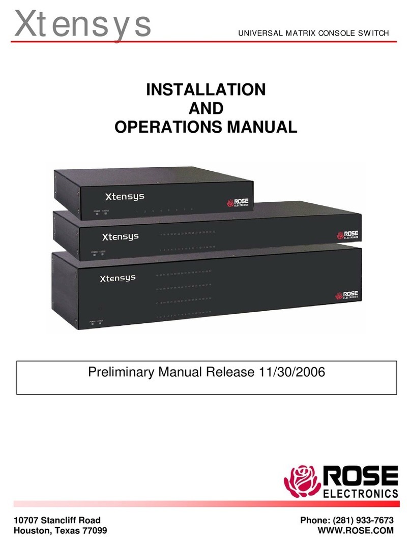
  9. Rose electronics ULTRAMATRIX 16X User manual

Rose electronics ULTRAMATRIX 16X User manual

10707 Stancliff Road Phone: (281) 933-7673
Houston, exas 77099 WWW.ROSE.COM
UL RAMA RIX 4X, 8X, AND 16X
INS ALLA ION AND OPERA IONS MANUAL
LIMI ED WARRAN Y
Copyright  Rose Electronics 1990 – 2002. All rights reserved.
No part of this manual may e reproduced, stored in a retrieval system, or transcri ed in any form or any means,
electronic or mechanical, including photocopying and recording, without the prior written permission of Rose
Electronics.
Rose Electronics Part # MAN-UMX – 1.1
Printed In the United States of America  Revision 1.1
Rose Electronics warrants the UltraMatrix™ to e in good working order for one year from the date of purchase from
Rose Electronics or an authorized dealer. Should this product fail to e in good working order at any time during this
one-year warranty period, Rose Electronics will, at its option, repair or replace the Unit as set forth elow. Repair
parts and replacement units will e either reconditioned or new. All replaced parts ecome the property of Rose
Electronics. This limited warranty does not include service to repair damage to the Unit resulting from accident,
disaster, a use, or unauthorized modification of the Unit, including static discharge and power surges.
Limited Warranty service may e o tained y delivering this unit during the one-year warranty period to Rose
Electronics or an authorized repair center providing a proof of purchase date. If this Unit is delivered y mail, you
agree to insure the Unit or assume the risk of loss or damage in transit, to prepay shipping charges to the warranty
service location, and to use the original shipping container or its equivalent. You must call for a return authorization
num er first. Under no circumstances will a unit e accepted without a return authorization num er. Contact an
authorized repair center or Rose Electronics for further information.
ALL EXPRESS AND IMPLIED WARRANTIES FOR THIS PRODUCT INCLUDING THE WARRANTIES OF
MERCHANTABILITY AND FITNESS FOR A PARTICULAR PURPOSE, ARE LIMITED IN DURATION TO A PERIOD
OF ONE YEAR FROM THE DATE OF PURCHASE, AND NO WARRANTIES, WHETHER EXPRESS OR IMPLIED,
WILL APPLY AFTER THIS PERIOD. SOME STATES DO NOT ALLOW LIMITATIONS ON HOW LONG AN IMPLIED
WARRANTY LASTS, SO THE ABOVE LIMITATION MAY NOT APPLY TO YOU.
IF THIS PRODUCT IS NOT IN GOOD WORKING ORDER AS WARRANTED ABOVE, YOUR SOLE REMEDY
SHALL BE REPLACEMENT OR REPAIR AS PROVIDED ABOVE. IN NO EVENT WILL ROSE ELECTRONICS BE
LIABLE TO YOU FOR ANY DAMAGES INCLUDING ANY LOST PROFITS, LOST SAVINGS OR OTHER
INCIDENTAL OR CONSEQUENTIAL DAMAGES ARISING OUT OF THE USE OF OR THE INABILITY TO USE
SUCH PRODUCT, EVEN IF ROSE ELECTRONICS OR AN AUTHORIZED DEALER HAS BEEN ADVISED OF THE
POSSIBILITY OF SUCH DAMAGES, OR FOR ANY CLAIM BY ANY OTHER PARTY.
SOME STATES DO NOT ALLOW THE EXCLUSION OR LIMITATION OF INCIDENTAL OR CONSEQUENTIAL
DAMAGES FOR CONSUMER PRODUCTS, SO THE ABOVE MAY NOT APPLY TO YOU. THIS WARRANTY
GIVES YOU SPECIFIC LEGAL RIGHTS AND YOU MAY ALSO HAVE OTHER RIGHTS WHICH MAY VARY FROM
STATE TO STATE.
IBM ®, AT, and PS/2 are trademarks of International Business Machines Corp.
Microsoft ® and Microsoft Windows™ are registered trademarks of Microsoft Corp.
Apple, Macintosh, and ADB are trademarks of Apple Computer, Inc.
Sun is a registered trademark of Sun MicroSystems Inc.
Any other trademarks mentioned in this manual are acknowledged to e the property of the trademark owner.
NOTE: This equipment has een tested and found to comply with the limits for a Class A digital device,
pursuant to Part 15 of the FCC Rules. These limits are designed to provide reasona le protection
against harmful interference when the equipment is operated in a commercial environment. This
equipment generates, uses, and can radiate radio frequency energy and, if not installed and used in
accordance with the instruction manual, may cause harmful interference to radio communications.
Operation of this equipment in a residential area is likely to cause harmful interference in which case the
user will e required to correct the interference at his own expense.
FCC/IC S A EMEN S, EU DECLARA ION OF CONFORMI Y
FEDERAL COMMUNICA IONS COMMISSION AND INDUS RY CANADA
RADIO-FREQUENCY IN ERFERENCE S A EMEN S
This equipment generates, uses, and can radiate radio frequency energy and if not installed and used properly, that
is, in strict accordance with the manufacturer’s instructions, may cause interference to radio communication. It has
een tested and found to comply with the limits for a Class A digital device in accordance with the specifications of
Part 15 of FCC rules, which are designed to provide reasona le protection against such interference when the
equipment is operated in a commercial environment. Operation of this equipment in a residential area is likely to
cause interference, in which case the user at his own expense will e required to take whatever measures may e
necessary to correct the interference.
Changes or modifications not expressly approved y the party responsi le for compliance could void the user’s
authority to operate the equipment. This digital apparatus does not exceed the Class A limits for radio noise
regulation of industry Canada.
Le présent appareil numérique n’émet pas de ruits radioélectriques dépassant les limites applica les aux appareils
numériques de la classe A prescrites dans le Règlement sur le rouillage radioélectrique pu lié par Industrie
Canada.
EUROPEAN UNION DECLARA ION OF CONFORMI Y
ACCORDING O COUNCIL DIREC IVE 89/336EEC
This equipment is in conformity with the requirements of the European
EMC directive 89/336/EEC in respect of:
EN55022: (Class A)
EN50082-1 / EN60555-2, and
The Low Voltage Directive.
ABLE OF CON EN S
I
Contents
Disclaimer................................................................................................................................................................. 1
A out this manual .....................................................................................................................................................1
Introduction............................................................................................................................................................... 1
Features................................................................................................................................................................ 2
Upgrada ility...................................................................................................................................................... 2
Security.............................................................................................................................................................. 2
Flexi ility............................................................................................................................................................ 2
On-screen display technology ............................................................................................................................2
Compati ility ...................................................................................................................................................... 2
Ca le requirements............................................................................................................................................3
Package content ................................................................................................................................................ 3
Rose Electronics we site ..................................................................................................................................3
UltraMatrix models ....................................................................................................................................................4
System overview.......................................................................................................................................................5
KVM station .......................................................................................................................................................5
KVM Station Key oard and Mouse..................................................................................................................... 5
KVM Station Video Monitor ................................................................................................................................5
Computers ......................................................................................................................................................... 5
Expansion.......................................................................................................................................................... 5
RS232 port......................................................................................................................................................... 8
Ca ling .............................................................................................................................................................. 8
System security..................................................................................................................................................8
Site planning.............................................................................................................................................................9
Switch installation – Single unit ............................................................................................................................... 10
Multi-switch installation – General ........................................................................................................................... 12
Multi-switch installation – BUS topology .................................................................................................................. 12
Multi-switch installation – RING topology................................................................................................................. 15
Multi-switch installation – Split BUS topology........................................................................................................... 18
Multi-switch installation – Staggered BUS topology ................................................................................................. 20
Menu System.......................................................................................................................................................... 24
Main Menu....................................................................................................................................................... 24
Configure system ............................................................................................................................................. 25
Configure computers........................................................................................................................................ 28
Configure KVM................................................................................................................................................. 30
Configure user ................................................................................................................................................. 32
Configure Profile .............................................................................................................................................. 33
Configure Group .............................................................................................................................................. 35
Configure language.......................................................................................................................................... 36
System status .................................................................................................................................................. 37
Save menu....................................................................................................................................................... 38
User operating instructions...................................................................................................................................... 39
Key oard commands........................................................................................................................................... 39
Serial port usage (RS232)....................................................................................................................................... 41
Connecting the Serial Ca le............................................................................................................................. 41
Setting up Windows HyperTerminal.................................................................................................................. 41
Starting a serial communication session........................................................................................................... 41
Serial menu options ......................................................................................................................................... 42
Switching using the serial port ............................................................................................................................. 45
Serial device support............................................................................................................................................... 46
Service Information ................................................................................................................................................. 47
Maintenance and Repair...................................................................................................................................... 47
Technical Support................................................................................................................................................ 47
Safety ..................................................................................................................................................................... 48
Safety and EMC Regulatory Statements.............................................................................................................. 48
Trou leshooting ...................................................................................................................................................... 50
II
Figures
Figure 1. UltraMatrix models..................................................................................................................................... 4
Figure 2. UM4 Expansion card.................................................................................................................................. 6
Figure 3. UM8 or UM16 Expansion card ................................................................................................................... 7
Figure 4. Installation - Single unit.............................................................................................................................10
Figure 5. UM4 BUS topology ...................................................................................................................................14
Figure 6. UM8 BUS topology ...................................................................................................................................14
Figure 7. UM16 BUS topology .................................................................................................................................14
Figure 8. UM4 Ring topology ...................................................................................................................................17
Figure 9. UM8 Ring topology ...................................................................................................................................17
Figure 10. UM16 Ring topology ...............................................................................................................................17
Figure 11. UM4 Split BUS........................................................................................................................................19
Figure 12. UM8 Split BUS........................................................................................................................................19
Figure 13. UM4 Staggered BUS...............................................................................................................................22
Figure 14. UM8 Staggered BUS...............................................................................................................................22
Figure 15. UM16 Staggered BUS.............................................................................................................................22
Figure 16. Menu structure........................................................................................................................................23
Figure 17. Main configuration menu.........................................................................................................................24
Figure 18. Configure system menu ..........................................................................................................................25
Figure 19. Configure computer menu.......................................................................................................................28
Figure 20. Configure KVM menu..............................................................................................................................30
Figure 21. Configure user menu...............................................................................................................................32
Figure 22. Configure profile menu............................................................................................................................33
Figure 23. Configure group menu ............................................................................................................................35
Figure 24. Configure language menu.......................................................................................................................36
Figure 25. System status display .............................................................................................................................37
Figure 26. Save menu .............................................................................................................................................38
Figure 27. Login screen ...........................................................................................................................................40
Figure 28. Computer select menu............................................................................................................................40
Figure 29. Connection status messages ..................................................................................................................40
Figure 30. Serial menu ............................................................................................................................................42
Figure 31. Serial support..........................................................................................................................................46
ables
Ta le 1. UM4 Expansion card connector description................................................................................................. 6
Ta le 2. UM8/16 Expansion card connector description............................................................................................ 7
Ta le 3. Key oard commands .................................................................................................................................39
Appendices
Appendix A. Initial factory default settings ................................................................................................................52
Appendix B. General specifications..........................................................................................................................53
Appendix C. Parts and ca les..................................................................................................................................54
Appendix D. Status Connect / Failure Reason Summary..........................................................................................55
Appendix E. Disconnect Status Reasons .................................................................................................................55
Appendix F. KVM placement / conflicts....................................................................................................................56
Appendix G. Password jumper.................................................................................................................................56
Appendix H. Diagnostic check / error messages ......................................................................................................57
Appendix I. Rack mount..........................................................................................................................................58
Appendix J. Rack mount illustration .........................................................................................................................58
Appendix K. Video distance ta le.............................................................................................................................59
IN RODUC ION
UL RAMA RIX “UMX” SERIES INS ALLA ION AND OPERA IONS MANUAL 1
Disclaimer
While every precaution has een taken in the preparation of this manual, the manufacturer assumes no responsi ility
for errors or omissions. Neither does the manufacturer assume any lia ility for damages resulting from the use of the
information contained herein. The manufacturer reserves the right to change the specifications, functions, or circuitry
of the product at any time without notice.
The manufacturer cannot accept lia ility for damages due to misuse of the product or other circumstances outside
the manufacturer’s control. The manufacturer will not e responsi le for any loss, damage, or injury arising directly
or indirectly from the use of this product.
(See limited warranty)
About this manual
This manual covers the installation, configuration, and the operation of the UltraMatrix “X” series switches. The
installation section is organized into sections, a single unit installation section, a section for the installation of the
different topologies, the serial port functions, configuration menus, and the system operation. Each topology
installation section covers the different models.
Introduction
Thank you for choosing Rose Electronics
®
UltraMatrix™ Key oard-video-mouse matrix switch with on-screen display
capa ilities. The UltraMatrix switch is the results of Rose Electronics commitment to providing continued state-of-
the-art switching solutions for today’s demanding workplace. The UltraMatrix has proven to e a valua le investment
for all types of usinesses that have the need to monitor, maintain, and access information from multiple computer
systems. Its use in large computer facilities gives the IT professional the added flexi ility to monitor and maintain
hundreds of systems, running on different platforms, from one or multiple KVM stations. The UltraMatrix switch is the
common sense switching solution that provides the flexi ility, integrity, and security required for today’s usiness
environment.
The advanced on-screen display (OSD) menus guide you through the configuration process with on-screen
information for each configuration section, making it easy to configure the UltraMatrix, the KVM stations, the
computers, and security for the system. There are additional configuration parameters that can e used to
personalize the look of the menus and dialog oxes. A help line is provided for each menu selection giving a
rief explanation of the selected menu item.
Rose Electronics UltraMatrix switches are designed to meet you switching needs, whatever your system demands
are, one user of multiple users, one computer or hundreds. All models offer standard features that allow for easy,
secure, and complete access to as many as 1,000 computers from one or multiple KVM stations.
Relia ility, security, flash memory technology, and other features ensure the UltraMatrix switch will streamline your
data center or server room and simplify the maintenance, access and updating of your systems.
NOTE: A Key oard, Video monitor, and Mouse are referred to through this manual as a KVM station
UL RAMA RIX “UMX” SERIES INS ALLA ION AND OPERA IONS MANUAL
2
Features
Upgradability



Free lifetime ase firmware upgrades, ased on flash memory technology, provide new features and
improvements. Base firmware upgrades are availa le from our we site at www.rose.com.
Security



Unique configuration password for persons authorized to perform configuration maintenance.



User names and passwords allow controlled access to computers with sensitive information, system data, or
restricted applications.



Computers can e assigned to a unique group, allowing authorized access only.



Four connect modes; View, Share, Control, and Private provide flexi ility in configuring the UltraMatrix switch to
conform to your security requirements.



Profiles can e defined and assigned to each user that defines which computers they have access to and the
connect mode.
Flexibility



Modular design makes for easy installation, maintenance, and expanda ility.



Plug-in expansion oards make the UltraMatrix switch easy to extend to other switches.



Pre-configuration of the switch allows for installation without powering the computers/servers down.



Switching to computers can e done y key oard commands, an on-screen list of computers, or y commands
through the RS232 serial port.



Multi-language capa ilities.



Integrated auto-switching power supply accepts 90-240 VAC sources.
On-screen display technology



The UltraMatrix video pops-up over the computer application display or is automatically generated.



Easy to use menus guide you through the configuration process.



The connection status for all computers can e displayed.



Menus and display windows can e configured with solid or transparent colors.



One of four screen saver options can e selected.
Compatibility



A variety of hardware platforms can e connected simultaneously to the UltraMatrix switch without interference,
including PCs, Sun systems, IBM RS/6000, HP, DEC, SGI, and others.



Full key oard and mouse emulation and video resolutions up to 1600 x 1200 ensures trou le-free access to most
software applications.



Serial support using VT100, VT102, and VT202 terminal emulation.



Standard TTY mode automatically scrolls incoming data.
KVM compatibility
Key oards PC, Unix, and most US and foreign QWERTY key oards, Japanese and Korean key oards with or
without Windows keys, 101, 102, 104, 105, 106, 109, Sun. Some older XT/AT auto-sensing or single
mode key oards may not e compati le.
Monitors VGA, SVGA, XGA, Composite
Mice Standard PS/2, PS/2 wheel, Sun
CPU compatibility
Computers Industry standard PCs, Unix systems, Sun, IBM RS/6000, DEC, HP, SGI, Apple, and others
Key oards Standard PC mode 1, 2, or 3 in PS/2 or AT, USB, Sun, Apple ADB*. Some older XT/AT auto-sensing
or single mode key oards may not e compati le.
Monitors VGA, SVGA, XGA, Composite, Sync-of-green
Mice Standard PS/2, PS/2 wheel, Serial (2 or 3 utton), USB, Sun, Apple ADB*
* Requires use of Rose translator: CNV-MACPS and Rose ca le.
UL RAMA RIX “UMX” SERIES INS ALLA ION AND OPERA IONS MANUAL 3
Cable requirements
The ca le requirements for your system will vary depending on the types of CPUs connected to the UltraMatrix
switch and the equipment used for the KVM stations. A KVM adapter ca le is needed for each KVM station, a CPU
adapter ca le is needed for each computer/server that is connected to the UltraMatrix, and if the units are connected
in an expansion topology, expansion ca les will e needed to connect the units together.
(See Appendix C for ca le part num ers)
Package content
The shipping package content consists of the following:



The UltraMatrix switch



Power cord (North American shipments only)



RJ12 serial ca le



RJ to DB9 adapter



Installation and operations manual
CPU, KVM, and expansion ca les are usually shipped separately. If the package contents are not correct, contact
Rose Electronics or your reseller, so the discrepancy can e quickly resolved.
Rose Electronics web site
Visit our we site at www.rose.com for additional information on the UltraMatrix switch and other products offered y
Rose Electronics that are designed for data center applications, classroom environments, and many other switching
and extending applications.
MODELS
UL RAMA RIX “UMX” SERIES INS ALLA ION AND OPERA IONS MANUAL
4
UltraMatrix models
UltraMatrix – Rear panel Model num er
4X model
UM4-aX U/E
a = # users (0-4)
= # CPUs (4, 8, 12, 16)
/E = expansion card installed
8X model
UM8-aX U/E
a = # users (0-4)
= # CPUs (4, 8, 12, 16)
/E = expansion card installed
16X model
UM16-aX U/Ec
a = # users (0-4)
= # CPUs (4, 8, 12, 16)
/Ec, c = num er of expansion cards
installed (1 or 2)
Figure 1. UltraMatrix models
OVERVIEW
UL RAMA RIX “UMX” SERIES INS ALLA ION AND OPERA IONS MANUAL 5
System overview
The UltraMatrix switch is designed with the latest in KVM switching technology. It has the capa ility and flexi ility to
configure to most key oards, video monitors, mice, servers and computers. The modular design of the UltraMatrix
makes the unit easy to install, expand, and maintain. The addition of an expansion card(s) and additional switches
can increase the num er of computers that can e accessed up to 1,000. The complete system consists of the
UltraMatrix switch or switches if the system is expanded, one or more KVM stations, and the computers/servers that
will e connected.
KVM station
A KVM station, consisting of a Key oard, Video monitor, and Mouse, connects to the DB25F KVM connectors on the
rear panel using a KVM adapter ca le. The KVM adapter ca le is availa le with a variety of connector types to
accommodate the different types of key oards, video monitors and mice. The KVM adapter ca le connectors must
e compati le with the key oard, video monitor, and mouse ca le connectors.
KVM adapter ca les are availa le in lengths of 1 – 100 feet.
(Refer to the compati ility ta le on page 2)
KVM Station Keyboard and Mouse
The KVM stations must use a PS/2 key oard and mouse or a Sun Key oard and Mouse.
Note: When using a PS/2 key oard, the PS/2 key oard must e capa le of communicating in Mode 2 and Mode 3 if
any of the CPU key oards are PC Mode 3, USB, SUN, or if a Rose Translator is used in conjunction with an
Apple computer. If a connected CPU uses a serial mouse, the UltraMatrix will convert the PS/2 KVM mouse
movements and present it in serial form to the serial port of that connected CPU.
KVM Station Video Monitor
The KVM Station video monitor must e capa le of supporting the resolution, frequency, and sync type eing sent y
all connected computer. It is recommended that the KVM monitor e a multi-sync monitor capa le of resolutions up
to 1280 x 1024 @ 75Hz or etter. The quality of the video depends largely on the type of monitor used, the KVM
ca le length and ca le type. For ca le lengths greater than 20 feet, coax ca le must e used. Appendix K shows
the video quality distance ta le for different ca le types.
Computers
The computers that will e connected to the UltraMatrix can e PC’s, Unix systems, Sun systems, and Apple
computers. (Refer to the compati ility ta le on page 2)
The CPU connectors on all UltraMatrix models are DB25F. Each connected computer uses a CPU adapter ca le
compati le with the computer’s key oard, monitor, and mouse ports. The CPU adapter ca le must have the correct
key oard, video monitor and mouse connectors to connect to the CPUs ports.
CPU adapter ca les are availa le in lengths of 5 – 100 feet.
The UltraMatrix switch can support computers and serial devices such as routers and hu s, which require a serial
interface. A special ca le is used to connect from the UltraMatrix CPU connector (DB25F) to a serial device interface
(Dum Terminal, CPU, or serial device).
The UltraMatrix switches CPU port must first e configured for serial functions. Serial CPU ca les are availa le in
DB25M to:



DB9



DB25



RJ11



RJ12



RJ45



MD8
Expansion
When configured in an expanded topology, the expansion connectors on the expansion card provide the means of
sending the system, key oard, video, and mouse data from one UltraMatrix switch’s expansion card output to
another UltraMatrix switch’s expansion card input. This allows a KVM station on one UltraMatrix to switch to a
computer connected on another UltraMatrix. Expansion ca les are needed for each expansion Unit. The expansion
ca les needed are DB15MF for the 4X model and HD15MF for the 8X and 16X models.
Expansion ca les are availa le in lengths of 2 – 250 feet.
UL RAMA RIX “UMX” SERIES INS ALLA ION AND OPERA IONS MANUAL
6
To expand the UltraMatrix switch in an expanded configuration, an expansion card must e installed in each
UltraMatrix switch. Figure 2 shows the expansion card used for the “4X” model, Figure 3 shows the expansion card
used for the 8X and 16X models. The 16X model has an upper and lower expansion card installed.
Out 1 and In 1 connectors on the expansion card transmit and receive all key oard, mouse and system signals and
the video signals for KVM 1 and KVM 2. In an expanded system, expansion ca les must e connected from the
Out 1 connector on one unit to the In 1 connector on another unit for the expanded system to work ecause all
system control information is transmitted and received from these ports.
Jumper JP3 or JP15 must e removed from the expansion cards on two Units in the RING topology to properly
maintain ca le termination. To identify which Units must have jumper JP3 or JP15 removed, calculate the total ca le
length around the “RING”. This is from Unit #1’s “IN” connector, around the “RING” and ack to Unit #1’s “OUT”
connector.
Jumper JP15 (UM4 model) or JP3 (UM8 model and UM16 model-lower card) should e removed on Unit #1 and
another switch in the system that will divide the “RING” into approximately equal ca le length distances.
To remove an expansion card and install/remove any jumpers, perform the following:
1. Remove power from the UltraMatrix switch.
2. Remove any expansion ca les. (Note the connectors they are attached to)
3. Unscrew the two screws securing the expansion card to the chassis.
4. Carefully pull the expansion card straight ack until it unseats from the ackplane connector.
5. Remove/install the needed jumpers (JP15 on the 4X model / JP1, JP2 or JP3 on the 8X/16X models)
6. Re-install the expansion card. Make sure it seats properly in the ackplane connector.
7. Secure the expansion card with the two screws.
8. Replace the expansion ca les to the correct connectors.
Figure 2. UM4 Expansion card
IN1 Receives all key oard, mouse, system data and video signals for KVM 1 and KVM2
OUT1 Transmits all key oard, mouse, system data and video signals for KVM 1 and KVM2
BUS 1 & 2
IN2 Receives video signals for KVM 3 and KVM 4
OUT2 Transmits video signals for KVM 3 and KVM 4
BUS 3 & 4
Ta le 1. UM4 Expansion card connector description
OU 2 IN2 OU 1 IN1
IN1 OU 1 IN2 OU 2
JP15
JUMPER OFF-RING
JUMPER ON-BUS
UL RAMA RIX “UMX” SERIES INS ALLA ION AND OPERA IONS MANUAL 7
Figure 3. UM8 or UM16 Expansion card
UM8 expansion card and lower expansion card on the UM16 model
IN1 Receives all key oard, mouse, system data and video signals for KVM 1 and KVM2
OUT1 Transmits all key oard, mouse, system data and video signals for KVM 1 and KVM2
BUS1 & 2
IN2 Receives video signals for KVM 3 and KVM 4
OUT2 Transmits video signals for KVM 3 and KVM 4
BUS 3 & 4
IN3 Receives video signals for KVM 5 and KVM 6
OUT3 Transmits video signals for KVM 5 and KVM 6
BUS 5 & 6
IN4 Receives video signals for KVM 7 and KVM 8
OUT4 Transmits video signals for KVM 7 and KVM 8
BUS 7 & 8
Upper expansion card on the UM16 model
IN1 Receives video signals for KVM 9 and KVM 10
OUT1 Transmits video signals for KVM 9 and KVM 10
BUS 9 & 10
IN2 Receives video signals for KVM 11 and KVM 12
OUT2 Transmits video signals for KVM 11 and KVM 12
BUS 11 & 12
IN3 Receives video signals for KVM 13 and KVM 14
OUT3 Transmits video signals for KVM 13 and KVM 14
BUS 13 & 14
IN4 Receives video signals for KVM 15 and KVM 16
OUT4 Transmits video signals for KVM 15 and KVM 16
BUS 15 & 16
Ta le 2. UM8/16 Expansion card connector description
OU 1 IN1 OU 2 IN2 OU 3 IN3 OU 4 IN4
IN4 OU 4 IN3 OU 3 IN2 OU 2 IN1 OU 1
KVM 1-4 KVM 5-8 KVM 9-12 KVM 13-16
UPPER CARD
LOWER CARD
JP1 & JP2
JUMPER
SE INGS
JP2 JP1
UP
DOWN
UP
DOWN
JUMPER OFF-RING
JUMPER ON-BUS
JP3
UL RAMA RIX “UMX” SERIES INS ALLA ION AND OPERA IONS MANUAL
8
Jumpers JP1 and JP2 set the KVM assignments for the UM8 and UM16 models. On the UM8 model, setting jumpers
JP1 and JP2 in the “DOWN” position sets the KVM ports for that Unit to KVM 1-4. In the “UP” position, the KVM ports
are set to KVM 5-8.
On the UM16 model, setting jumpers JP1 and JP2 to the “DOWN” position on the ottom expansion card sets the
KVM ports to KVM 1-4. Setting JP1 and JP2 to the “UP” position on the ottom card sets the KVM ports to KVM 5-8.
On the upper card, setting jumpers JP1 and JP2 to the “DOWN” position sets the KVM ports to KVM 9-12. In the
“UP” position, the KVMs are set to KVM 13-16.
In a typical UM8 expanded system, JP1 and JP2 are usually set for:
Unit #1 to KVMs 1-4 (JP1 & JP2 =”DOWN”)
Unit #2 to KVMs 5-8 (JP1 & JP2 = “UP)
Unit #3 to KVMs 1-4 (JP1 & JP2 =”DOWN”)
Unit #4 to KVMs 5-8 (JP1 & JP2 =”UP”)
A typical UM16 expanded system, JP1 and JP2 are usually set for:
Unit #1 to KVMs 1-4 (Bottom card, JP1 & JP2 =”DOWN” / Top card, JP1 & JP2 =Removed)
Unit #2 to KVMs 5-8 (Bottom card, JP1 & JP2 =”UP” / Top card, JP1 & JP2 = Removed)
Unit #3 to KVMs 9-12 (Top card, JP1 & JP2 =”DOWN” / Bottom card, JP1 & JP2 = Removed)
Unit #4 to KVMs 13-16. (Top card, JP1 & JP2 =”UP” / Bottom card, JP1 & JP2 = Removed)
RS232 port
All UltraMatrix switches are equipped with an RS232 serial port for each installed system CPU card. These ports are
RJ12, 6-conductor connectors. They provide a serial interface to the UltraMatrix from a computer terminal, a stand-
alone computer, or a note ook computer that is not connected to any CPU port.
The RS232 serial port ena les you to:



Upgrade the system firmware



Restore the unit to its factory default settings



Configure an expansion switch



Switch any KVM station to any CPU port
An adapter and serial ca le are provided for serial interface.
Firmware cannot e upgraded from a computer terminal.
Cabling
KVM stations, computers and servers, and expansion units are easily connected to the UltraMatrix switch with the
proper ca les. Ca les are usually purchased along with the UltraMatrix to provide quick, trou le-free installation.
Provide adequate strain relief for the CPU, KVM, and expansion ca les to relieve excess tension on the connectors.
System security
Security is a very important concern, especially in the environments most UltraMatrix switches are commonly
installed in, such as data centers and server rooms. The UltraMatrix system can e secured with a unique
configuration password allowing only authorized personnel access to the configuration menus and the system set-up
functions, including creating and assigning users, profiles, and groups.
The KVM stations can also e secured y assigning user access names and passwords that restrict access to
certain computers or servers that contain sensitive information or restricted applications.
Other security functions include the flexi ility of assigning certain computers or servers to a unique Group. This
feature allows you to group computers or servers together for access y defined “Profiles”. These profiles can e
set-up to define the way computers within a “Group” are accessed.
The security functions, “Users”, “Profiles”, and “Groups” are configured from the main configuration menu and when
set-up, form a flexi le, relia le, and secure system. These functions are explained in detail in the menu section and
the site planning section.
Avoid routing ca les close to fluorescent lights, air compressors, high voltage power sources and
machinery that may create electrical noise or interference with the operation of the UltraMatrix switch.
SI E PLANNING
UL RAMA RIX “UMX” SERIES INS ALLA ION AND OPERA IONS MANUAL 9
Site planning
Organizing your site and planning the placement of the computers, the KVM stations, the UltraMatrix switches, and
the routing of the ca les is a key part in the installation and configuration process. Care should e taken when
connecting the computers, KVMs, and the UltraMatrix switches. Locate the UltraMatrix as close as possi le to the
computers so the ca les are as short as possi le ut still give some freedom of movement. Using shorter ca les
keeps the video noise to a minimum and reduces installation costs. Provide proper strain relief for all ca les.
The UltraMatrix switch can e rack mounted with Rose Electronics rack mount kit (see Appendix I & J). Another
option that makes for a clutter free installation is the Rose Electronics RackView™. The RackView is a complete
KVM station (key oard, LCD monitor, and mouse) all in a compact, pullout drawer that fits in 1 or 2 rack units. The
RackView can also e ordered with an optional UltraMatrix switch installed.
If your installation will consist of accessing your computers/servers remotely using Rose Electronics CrystalView
CAT5 or Fi er KVM extender or accessing over your Ethernet network or dial-up using our UltraLink, route these
ca les carefully and plan the placement of these products.
Wherever the UltraMatrix is located, it should e on a secure surface, free from o structions and o jects that may
cause damage to the Unit or an individual.
Following are a few items to consider prior to installing or configuring the UltraMatrix switch:



Determine which UltraMatrix switch will e Unit #1, #2, #3, etc.



Determine which computer will e connected to CPU port #1, #2, #3, etc.



Identify the computers that do not use a PC2 type key oard and a PS/2 mouse (default settings). Before
connecting these computers to a CPU port, the CPU port must e pre-configured to change the default key oard
and mouse types to the correct types.



Each computer can e assigned a unique computer name. Names like staff, marketing, and finance make it easy
to identify and connect to.
The default computer names are Computer x (x = 1 – 1,000)



The KVM stations can also e assigned a unique KVM name.
The default KVM names are KVM x (x = 1 – 4)



Access to the system set-up and configuration menus can e limited y assigning a configuration password.



Access to the computers can e limited y assigning each user a unique user ID and password and configuring
the switch to require a login.



Pre-plan the expansion ca le routing for expanded systems.
The configuration of the system, computers, KVM stations, users, profiles, and groups are defined in the menu
section.
INS ALLA ION
UL RAMA RIX “UMX” SERIES INS ALLA ION AND OPERA IONS MANUAL
10
Switch installation – Single unit
The asic installation of a single UltraMatrix switch is an easy and straightforward procedure. To install a single
switch, perform the elow steps for all computers/servers that will e connected. It is recommended that all
computers and servers e powered off. When a computer is connected and then ooted, the UltraMatrix will
automatically determine the key oard and mouse types used for that computer and no pre-configuration of the CPU
port is needed. If removing power from a computer or server is not practical, pre-configure the UltraMatrix’s CPU
port to define that CPU port’s key oard and mouse types. The default key oard type is PC mode 2 and the mouse
type is PS/2. If the computer eing connected uses a PC2 key oard and PS/2 mouse, no pre-configuration of the
CPU port is needed. If not, pre-configure the CPU port (Steps 5a-f) for the key oard and mouse types for that CPU
efore connecting the computer. This procedure should only e done if the CPUs key oard and mouse can e
disconnected and re-connected with power applied to the computer without affecting the interface.
Figure 4. Installation - Single unit
PLEASE REFER O HE SAFE Y SEC ION
BEFORE INS ALLA ION
CPU’s 1
-
16
KVM’s 1
-
4
UL RAMA RIX “UMX” SERIES INS ALLA ION AND OPERA IONS MANUAL 11
Perform the following installation steps for each computer/server that will e connected to the UltraMatrix.
Sequentially connect the computers/servers starting with computer #1. (Refer to Figure 4)
Refer to the trou leshooting section for help if needed.
NOTE: When entering information into the UltraMatrix menu system, use the numeric keys a ove the key oard for
entering num ers. The numeric keypad cannot e used for entering information into the menu system.
Command inputs to the menu system must e entered within 2 seconds of each other or the input is a orted.
Use the up/down and left/right arrow keys to maneuver within the menus. When the needed menu section is
highlighted, press enter. That menu will display, an input ox will display for a new value, or a choice ox will
display listing the supported choices for the selection.
Steps:
1. Connect all KVM stations to the UltraMatrix switches DB25F, KVM connectors using the appropriate KVM ca les.
2. Turn on all KVM stations video monitors and the UltraMatrix switch.
(Wait for the internal diagnostic check to complete)
3. Switch KVM station #1 to the CPU port eing configured (starting with CPU port #1). This is done y pressing
and releasing the left [Ctrl] key and within 2 seconds, type in the CPU port # eing configured (starting with 1)
and press [Enter]. A connection dialog ox will display showing the connection status. (Figure 29).
4. Pre-configure the CPU port, if needed, as outlined in steps 5a-f if the computer eing connected does not use a
PC2 type key oard or a PS/2 type mouse (defaults). Pre-configure the CPU port efore connecting the
computer or server. If the computer uses a PC2 type key oard and a PS/2 mouse, connect it to the
corresponding CPU port. No pre-configuration is needed, skip step 5 a-f.
5. Pre-Configuration procedure
a. Call up the “Main menu” y pressing and releasing the left [Ctrl] key, then the [F12] key. (See Figure 17)
. Select “Computer” and press [Enter]. (See Figure 19)
c. Select the computer to change the default key oard or mouse type, and then select the key oard or mouse
field for the selected computer and press [Enter]. A selection ox will display listing the supported key oard
or mouse types.
d. Select the correct key oard or mouse type for the selected computer and press [Enter].
e. Press [ESC] to return to the “Main menu” and save the changes.
f. Connect the computer to the pre-configured CPU port.
6. Boot the computer the KVM station is connected to if the computer power was off. You should see the oot-up
sequence on the KVM monitor. If the computer was connected to a pre-configured CPU port with power applied,
you should see that computers video.
7. Verify that the key oard, video, and mouse on the connected computer function properly efore proceeding.
Verify that other KVM stations operate properly.
8. Switch KVM station #1 to the next sequential CPU port as explained in step 3 and perform steps 4-7 for that
computer and for the remaining computers.
9. When all computers are connected and operating properly, change the “Maximum computers” value from the
default value of 64 to the correct num er of computers/servers connected to the single unit. This will limit the
scanning function to the actual num er of connected computers.
To change the “Maximum computers” value, perform the following:
10. Call up the “Main menu” (Left [Ctrl] key, [F12] See Figure 17)
11. Select “System” and press [Enter]. (See Figure 18)
12. Select “Maximum computers” and press [Enter]. An input ox will display for a new value.
13. Enter the correct “Maximum computers” value and press [Enter].
14. Press [ESC] to return to the “Main menu”.
15. Save the changes. (See Figure 26)
This completes the asic installation of a single Unit. You can switch to any connected computer from any KVM
station y pressing and releasing the left [Ctrl] key, typing in the computer port num er to switch to and press [Enter].
You can also switch to a computer y displaying the “Computer select” screen [Ctrl] + [ESC]. Select the computer to
switch to from the list and press [Enter]. You will e immediately switched to that computer.
To customize the configuration settings for the system, computers, KVM stations, users, profiles, groups, and
language, see the Configuration menu section for details. Refer to the Operation section for information on the
operation of the UltraMatrix switch.
UL RAMA RIX “UMX” SERIES INS ALLA ION AND OPERA IONS MANUAL
12
Multi-switch installation – General
The UltraMatrix switch can e installed in a variety of expanded topologies. The BUS, RING, Split BUS, and
Staggered BUS are the most common configurations. In any expanded system, each expansion port pair (Out1/ IN1)
on an expansion card carry the video information for two KVM stations (See Ta le 1 and Ta le 2). A KVM station
can connect to any computer, provided that KVM station’s video path has een routed to the corresponding
expansion port on the switch that the computer is connected to. When the expansion ca le path terminates, the
video path for that KVM pair stops. Examples of the ca ling and configuration of these four topologies are explained
for each of the three UltraMatrix models.
To egin installing any expanded topology, each UltraMatrix switch must e pre-configured with its “Starting
computer” num er. In the following examples, the “Starting computer” num er for Unit #1 is always 1 (default value).
Unit #2’s starting computer num er is the total num er of RS232 ports on Unit #1 times 4 plus 1. Using all 16 CPU
port models, the num er for the second unit would e 17. (4-RS232 ports times 4 plus 1). Unit #3’s “Starting
computer” num er would e 33. (Num er of RS232 ports on Unit #1 plus those on Unit #2 times 4 plus 1.)
Configure the “Starting computer” num er for each switch as follows:
Steps:
1. Connect a KVM station to the Unit eing configured (starting with Unit #2, Unit #1’s “Starting computer” num er
is, y default, 1)
2. Apply power to the KVM monitor and the UltraMatrix switch
(Wait for the internal diagnostic check to complete)
3. Call-up the “Main” configuration menu y pressing and releasing the left control [Ctrl] key, and within 2 seconds,
press the F12 key.
4. Select “System” and press [Enter]. The system menu will display. (See Figure 18)
5. Select “Starting computer” num er and press [Enter]. An input ox will display for a new “Starting computer”
num er. Type in the correct “Starting computer” num er for this Unit and press [Enter].
6. Press the “Esc” key to return to the “Main” menu.
7. Select “Save” and press [Enter]. A “YES/NO” choice ox will display. Select “YES” and press [Enter] to save the
changes. (See Figure 26)
8. Turn the power off on the UltraMatrix.
9. Connect the KVM station to the next unit to configure.
10. Perform steps 2-9 for this Unit and for all Units in the system.
When all Units have their correct “Starting computer” num er assigned, the expansion ca les can e connected.
The expansion ca les carry the system and video signals from one Unit’s OUT connector to another Unit’s IN
connector. When the “Starting computer” num er has een entered for each Unit, determine the KVM assignment
jumper settings (JP1 and JP2 for the UM8 and Um16 models) and set them accordingly. The UM4 model’s KVM
assignment is fixed and not user selecta le. (See Figure 3, Ta le 2, and KVM assignment information on page 6)
When the “Starting computer num er and the KVM assignment jumpers, JP1 and JP2 have een set, the expansion
ca les can e connected.
Multi-switch installation – BUS topology
Refer to Figure 5 for a typical BUS installation for the UM4 model, Figure 6 for the UM8 model, and Figure 7 for the
UM16 model.
The BUS installation is very similar to the single unit installation with the addition of connecting the expansion ca les
and changing two configuration parameters, the “Starting computer” num er for each unit and the “Maximum
computers” num er.
In a BUS topology, KVM stations on Unit #1 can access all computers. KVMs on Unit #2 can access all computers
except those on Unit #1. KVMs on Unit #3 can access all computers except those on Unit #2 and Unit #1.
The recommended way to connect the expansion ca les is to use the system “Status” display to verify the
connections. Following explains how to use the “Status” display and what to verify.
UL RAMA RIX “UMX” SERIES INS ALLA ION AND OPERA IONS MANUAL 13
Steps:
1. Connect a KVM station to Unit #1’s KVM #1 port. Turn on the KVM monitor and Unit #1.
(Wait for the internal diagnostic check is complete)
2. Call-up the “Main” menu y pressing and releasing the left control [Ctrl] key, then the F12 key.
3. From the “Main” menu, select “Status” and press [Enter]. The system “Status” display will appear.
The “Status” display shows the following information. (See Figure 25)
a. Computers
. Power (Power on status)
c. POS (Card position)
d. VER (Program version)
e. KVM
f. CPU
g. User
h. Status
The num er of system CPU ports that Unit #1 has will e highlighted under the Computers column. If the Unit is a
16-port Unit, computers 1-4, 5-8, 9-12, and 13-16 will e highlighted on the status screen.
(Note: “System CPU ports” = the total RS232 ports times 4)
BUS in the expansion Units as outlined in elow steps:
4. Apply power to the Unit to BUS in, then connect the expansion ca les (IN THIS ORDER):
From the “OUT 1” expansion card connector on the Unit eing added (Starting with Unit #2);
o the “IN 1” expansion card connector on the Unit already added (Starting with Unit #1).
(Always connect an expansion ca le to the “OUT 1” connector on the Unit eing added first, then to the “IN 1”
connector on the Unit already in the system. This procedure keeps the system properly terminated).
5. Verify on the system “Status” screen that the correct “System CPU ports” from the Unit eing added is
recognized. When Unit #2 is added, the “Status” display should highlight the total num er of system CPU ports
that Unit #1 and Unit #2 have. If oth Units have 16 CPU ports, computers 17-20, 21-24, 25-28, and 29-32
should also e highlighted.
6. Sequentially add the remaining Units to the BUS as descri ed in steps 4 and 5 and verify on the “Status” screen
that these “System CPU ports” are recognized.
Other expansion ca les connected from “OUT 2” to “IN 2”, “OUT 3” to “IN 3”, etc. can e added at any time after the
expansion ca les from the “OUT 1” connector to the “IN 1” connector have een added. When all BUS ca ling is in
place and reporting correctly to the “Status” screen, the computers can e connected to the UltraMatrix.
Connecting the computers
The computers that will e connected the UltraMatrix should already e identified as to what CPU port they will e
connected to and if that CPU port must e pre-configured to change the default key oard and/or mouse types. If the
computer eing connected does not use a PC2 type key oard or a PS/2 type mouse, pre-configure that CPU port as
descri ed in step 5 a-f on page 11 efore connecting the computer to the UltraMatrix.
(All UltraMatrix switches in the system should have power on, all expansion ca ling in place, pre-configuration of all
CPU ports needing pre-configuring completed, and no configuration menu displaying on any KVM stations monitor.)
7. Connect a KVM station to Unit #1’s KVM #1 connector using the appropriate KVM ca le and turn on the monitor.
8. Switch the KVM station to CPU port # “x” (starting with x=1) y pressing and releasing the left control [Ctrl] key,
then within 2 seconds, type in 1 (or the CPU port # the computer is eing connected to) and press [Enter]. A
connection dialog ox will display showing the connection status. (See Figure 29)
9. Connect the computer to its corresponding CPU port # (starting with port #1) using the appropriate CPU ca le.
10. Boot the computer if power is not applied. You should see the oot-up sequence on the KVM monitor. If the
computer was connected to a pre-configured CPU port with power applied, you should see that computers
video.
11. Verify that the key oard, video and mouse on the connected computer function properly efore proceeding.
12. Connect the next sequential computer to its corresponding CPU port and perform steps 8-11 for this computer
and for the remaining computers in the system.
UL RAMA RIX “UMX” SERIES INS ALLA ION AND OPERA IONS MANUAL
14
When all computers are connected to the UltraMatrix switches and functioning properly, the asic BUS installation is
complete. KVM stations connected to Unit #1 can switch to any computer in the system. Other configuration
parameters can e set-up for the system, computers, KVM stations, users, profiles, groups, and languages.
See the “Configuration menu” section and the Operations section for using the UltraMatrix switch.
These installation steps should e used as a guideline for installing multiple switches in a typical “BUS” topology.
Figure 5. UM4 BUS topology Figure 6. UM8 BUS topology
Figure 7. UM16 BUS topology

This manual suits for next models

5

Other Rose electronics Matrix Switcher manuals

Rose electronics UltraConsole Remote 2 User manual

Rose electronics

Rose electronics UltraConsole Remote 2 User manual

Rose electronics MultiVideo DVI User manual

Rose electronics

Rose electronics MultiVideo DVI User manual

Rose electronics ULTRAMATRIX 2xE User manual

Rose electronics

Rose electronics ULTRAMATRIX 2xE User manual

Rose electronics UltraMatrix AV User manual

Rose electronics

Rose electronics UltraMatrix AV User manual

Rose electronics ORION XC User manual

Rose electronics

Rose electronics ORION XC User manual

Rose electronics Xtensys User manual

Rose electronics

Rose electronics Xtensys User manual

Rose electronics UltraMatrix 4 User manual

Rose electronics

Rose electronics UltraMatrix 4 User manual

Rose electronics UltraMatix AV DVI User manual

Rose electronics

Rose electronics UltraMatix AV DVI User manual

Rose electronics EE2-2X16U/E User manual

Rose electronics

Rose electronics EE2-2X16U/E User manual

Rose electronics UltraMatrix AV User manual

Rose electronics

Rose electronics UltraMatrix AV User manual

Popular Matrix Switcher manuals by other brands

Leaf LHDMI44P manual

Leaf

Leaf LHDMI44P manual

Matrix Switch Corporation MSC-DE1664 product manual

Matrix Switch Corporation

Matrix Switch Corporation MSC-DE1664 product manual

Kramer VS-88HDCPxl user manual

Kramer

Kramer VS-88HDCPxl user manual

Scion-Tech SC38.MX16 user manual

Scion-Tech

Scion-Tech SC38.MX16 user manual

AMX AVS-OP-2004-347 Product View

AMX

AMX AVS-OP-2004-347 Product View

Network Technologies VEEMUX SM-nXm-15V-LCD Installation and operation manual

Network Technologies

Network Technologies VEEMUX SM-nXm-15V-LCD Installation and operation manual

Broadata LinkBridge LBS-88H2Q user manual

Broadata

Broadata LinkBridge LBS-88H2Q user manual

Kramer Sierra Pro XL 1208V5S Specifications

Kramer

Kramer Sierra Pro XL 1208V5S Specifications

Atlona AT-UHD-PRO3-88M manual

Atlona

Atlona AT-UHD-PRO3-88M manual

Abtus MAX-HDBT44/P User's operation guide

Abtus

Abtus MAX-HDBT44/P User's operation guide

Monoprice 21818 user manual

Monoprice

Monoprice 21818 user manual

geratech EGE-6UHD2-848AL manual

geratech

geratech EGE-6UHD2-848AL manual

Kramer 1616DEE Specifications

Kramer

Kramer 1616DEE Specifications

Avenview HDM-C6MX/WIP-SET Software upgrade guide

Avenview

Avenview HDM-C6MX/WIP-SET Software upgrade guide

Inline MSC0603 Operation manual

Inline

Inline MSC0603 Operation manual

Octava UHD44MX-IP install guide

Octava

Octava UHD44MX-IP install guide

AMX AVS-OCT-4864-567 Product View

AMX

AMX AVS-OCT-4864-567 Product View

AMX AVS-OCT-4832-217 Product View

AMX

AMX AVS-OCT-4832-217 Product View

manuals.online logo
manuals.online logoBrands
  • About & Mission
  • Contact us
  • Privacy Policy
  • Terms and Conditions

Copyright 2025 Manuals.Online. All Rights Reserved.