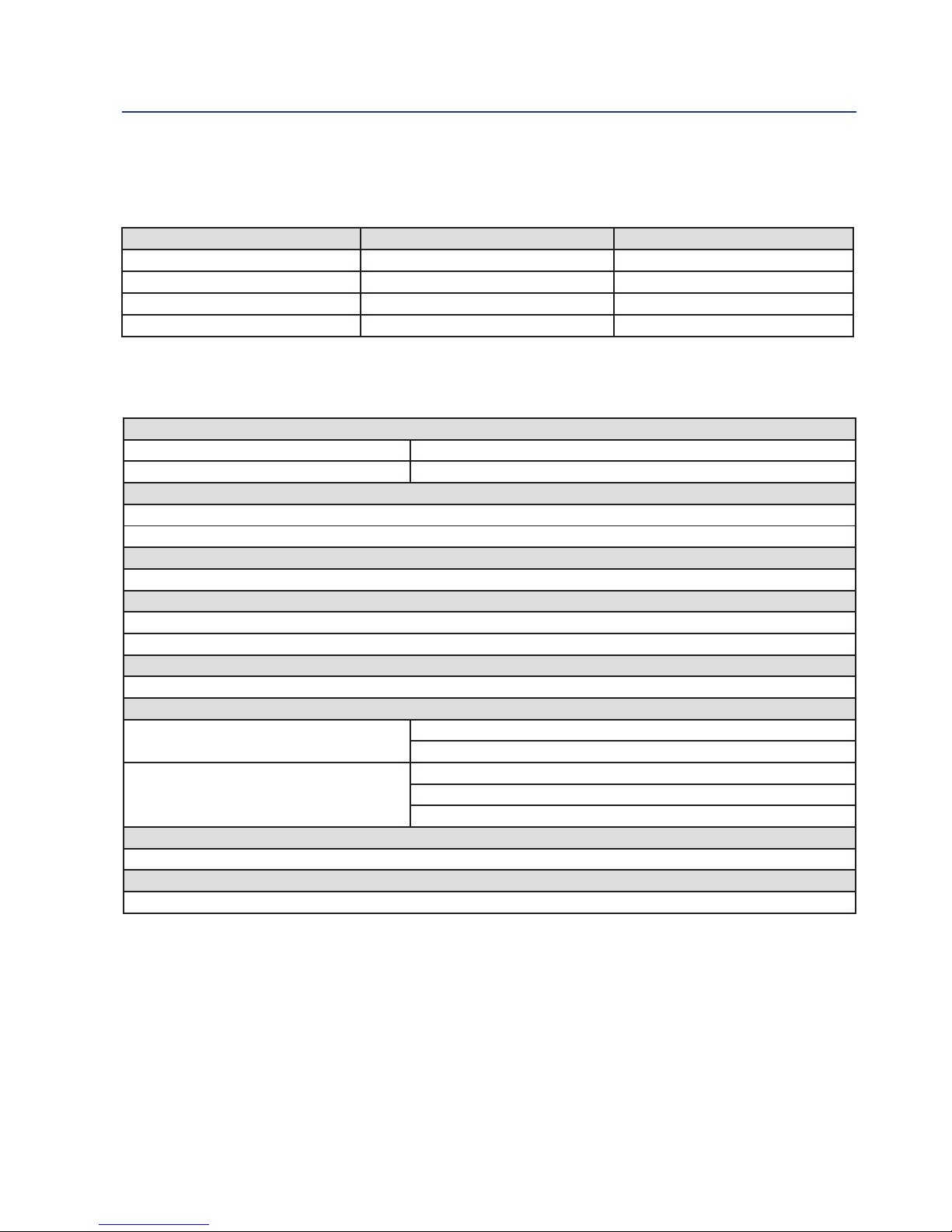
1.3 Product Certifications
Please see online certificates for further details.
ECEx
Sensors without preamp (pH and ORP) – Ex ia C T4 Ga (-20°C ≤ Ta ≤ +60°C)
Sensors with SMART preamp (pH only) – Ex ia C T4 Ga (-20°C ≤ Ta ≤ +60°C)
Per standards EC60079-0 : 2011, EC 60079-11 : 2011
ATEX
Sensors without preamp (pH and ORP) – 1 G Ex ia C T4 Ga (-20˚C ≤ Ta ≤ +60˚C)
Sensors with SMART preamp (pH only) – 1 G Ex ia C T4 Ga (-20˚C ≤ Ta ≤ +60˚C)
Per standards EN 60079-0: 2012+A11:2013, EN 60079-11:2012
FM
See online FM Certificate of Compliance for applicable sensor options:
ntrinsically Safe for use in Class , , and , Division 1, Groups A, B, C, D, E, F, and G; Temperature
Class T6 Ta = -20 °C to +60 °C
ntrinsically Safe for use in Class , Zone 0, AEx ia C T6 Ta = -20 °C to +60 °C
Nonincendive for use in Class , Division 2, Groups A, B, C, and D; Temperature Class T6 Ta = -20 °C
to +60 °C
Suitable for use in Class and , Division 2, Groups E, F, and G; Temperature Class T6 Ta = -20 °C
to +60 °C Hazardous (Classified) Locations
S/ , , /1/ABCDEFG/T6 Ta = 60°C - 1400332; Entity; /0/AEx ia C/T6 Ta = 60 °C - 1400332; Entity;
N / /2/ABCD/T6 Ta = 60 °C; S/ , /2/EFG/T6 Ta = 60 °C
Per standards 3600:1998, 3610:2010, 3611:2004, 3810:2005
CSA
See online CSA Certificate of Compliance for applicable sensor options:
Sensors with preamp – ntrinsically Safe:
Class , Division 1, Groups ABCD; Class , Division 1, Groups EFG; Class ; Class , Division 2, Groups
ABCD; Ambient temperature rating -20 °C to +60 °C; Ex ia C; T6
Sensors without preamp – ntrinsically Safe and Non- ncendive:
Class , Division 1, Groups ABCD; Class , Division 1, Groups EFG; Class ; Class , Division 2, Groups
ABCD; Ex ia C; T6; Ambient temperature rating -20 °C to +60 °C: (Simple Apparatus)
Per standards C22.2 No. 0-10, C22.2 No. 0.4-M2004, C22.2 No. 94-M1991, C22.2 No. 142 – M1987,
C22.2 No 157 – M1992, CAN/CSA E60079-0:07, CAN/CSA E60079- 11:02, UL50 11th Ed, UL508
17th Ed, UL913 7th Ed, UL 60079-0: 2005, UL 60079-11: 2002
Description and Specifications nstruction Manual
March 2017 LIQ-MAN-396R-396RVP
4 Descr pt on and Spec f cat ons