Installing with an ULTRIX-FR12 CAUTION
Before you set up and operate your unit, see the “Important Regulatory and Safety Notices to
Service Personnel” document that was included. The Ultripower User Guide, ULTRIX-FR12
Quick Start Guide and the ULTRIX-FR12 Install Guide are available from our website.
Have a question? Call our free,
24-hour technical support hotline to
speak with a live product specialist
located right here in our facility.
Tel: (+1) 844 • 652 • 0645
Page 2
1 4 1 41 4 1 4
ENET 1 ENET 2
ALARMLTC micro SD
R-OUT
SFP 1 SFP 2 LOOP
TERM
A B
2 3 4 5 6 7 8 91 10 11 13 14 15 1612
1
C DA B
Ultrix HDX-IO !REF A B
9 10 11 12 13 14 15 16
OUT
5 6 7 81 32 4 9 10 11 12 13 14 15 16
IN
5 6 7 832 4
C DA B
Ultrix HDX-IO !REF A B
9 10 11 12 13 14 15 16
OUT
5 6 7 81 32 4 9 10 11 12 13 14 15 16
IN
5 6 7 832 4
C DA B
Ultrix HDX-IO !REF A B
9 10 11 12 13 14 15 16
OUT
5 6 7 81 32 4 9 10 11 12 13 14 15 16
IN
5 6 7 832 4
C DA B
Ultrix HDX-IO !REF A B
9 10 11 12 13 14 15 16
OUT
5 6 7 81 32 4 9 10 11 12 13 14 15 16
IN
5 6 7 832 4
C DA B
Ultrix HDX-IO !REF A B
9 10 11 12 13 14 15 16
OUT
5 6 7 81 32 4 9 10 11 12 13 14 15 16
IN
5 6 7 832 4
C DA B
Ultrix HDX-IO !REF A B
9 10 11 12 13 14 15 16
OUT
5 6 7 81 32 4 9 10 11 12 13 14 15 16
IN
5 6 7 832 4
C DA B
Ultrix HDX-IO !REF A B
9 10 11 12 13 14 15 16
OUT
5 6 7 81 32 4 9 10 11 12 13 14 15 16
IN
5 6 7 832 4
C DA B
Ultrix HDX-IO !REF A B
9 10 11 12 13 14 15 16
OUT
5 6 7 81 32 4 9 10 11 12 13 14 15 16
IN
5 6 7 832 4
C DA B
Ultrix HDX-IO !REF A B
9 10 11 12 13 14 15 16
OUT
5 6 7 81 32 4 9 10 11 12 13 14 15 16
IN
5 6 7 832 4
C DA B
Ultrix HDX-IO !REF A B
9 10 11 12 13 14 15 16
OUT
5 6 7 81 32 4 9 10 11 12 13 14 15 16
IN
5 6 7 832 4
C DA B
Ultrix HDX-IO !REF A B
9 10 11 12 13 14 15 16
OUT
5 6 7 81 32 4 9 10 11 12 13 14 15 16
IN
5 6 7 832 4
C DA B
Ultrix HDX-IO !REF A B
9 10 11 12 13 14 15 16
OUT
5 6 7 81 32 4 9 10 11 12 13 14 15 16
IN
5 6 7 832 4
C DA B
Ultrix HDX-IO !REF A B
9 10 11 12 13 14 15 16
OUT
5 6 7 81 32 4 9 10 11 12 13 14 15 16
IN
5 6 7 832 4
C DA B
Ultrix HDX-IO !REF A B
9 10 11 12 13 14 15 16
OUT
5 6 7 81 32 4 9 10 11 12 13 14 15 16
IN
5 6 7 832 4
C DA B
Ultrix HDX-IO !REF A B
9 10 11 12 13 14 15 16
OUT
5 6 7 81 32 4 9 10 11 12 13 14 15 16
IN
5 6 7 832 4
C DA B
Ultrix HDX-IO !REF A B
9 10 11 12 13 14 15 16
OUT
5 6 7 81 32 4 9 10 11 12 13 14 15 16
IN
5 6 7 832 4
CAUTION: Risk of electrical shock. Enclosure shall be connected to earth ground via protective earth stud and 12AWG conductor or larger.
Read the user documentation for your Ultripowers and ULTRIX-FR12 before starting work or operating equipment.
NOTICE: The ULTRIX-FR12 frame does not have a power switch. Ensure that each Ultripower is not connected to mains power before
connecting the power cables from an Ultripower to the other components. If an Ultripower is energized as you connect the power cables to
the ULTRIX-FR12, the system could start to power up before it has enough power to operate and could damage the equipment.
Powering on the ULTRIX-FR12
2
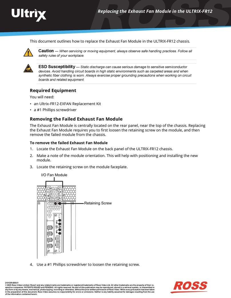
To verify that each Ultripower Output state is toggled to OFF
2a Locate the Ultricore BCS node in the Tree View of DashBoard.
2b Expand the main Ultricore BCS node.
2c Expand the Ultricore BCS sub-node to display a list of sub-nodes in the Tree View.
2d Expand the Devices sub-node.
2e Double-click the Ultripower Manager sub-node.
2f From the Group list, select the required Ultripower group.
2g Click OFF.
2h Verify that each Ultripower is the same state (Off). Refer to the Ultripower User Guide for details.
To cable two Ultripowers to the ULTRIX-FR12
2i Connect all four power cables from the ULTRIX-FR12 to the matching power connectors on the first Ultripower chassis.
2j Connect all four power cables from the ULTRIX-FR12 to the matching power connectors on the second Ultripower chassis.
To cable additional Ultripowers (optional)
Note: This procedure is only required when installing a high power redundancy setup.
2k Connect all four power cables from the ULTRIX-FR12 to the matching power connectors on the third Ultripower chassis.
2l Connect all four power cables from the ULTRIX-FR12 to the matching power connectors on the fourth Ultripower chassis.
To toggle the Ultripower Group to ON
2m Locate the Ultricore BCS node in the Tree View of DashBoard.
2n Expand the main Ultricore BCS node.
2o Expand the Ultricore BCS sub-node to display a list of sub-nodes in the Tree View.
2p Expand the Devices sub-node.
2q Double-click the Ultripower Manager sub-node.
2r Click ON.
NOTICE: The Output state of the grouped Ultripowers must be toggled to OFF before connecting to the ULTRIX-FR12.
CAUTION: Before setting an Ultripower Group to ON, ensure its Ultripower PSU average power output is below 5W.
Configuring the Ultripowers
1The ULTRIX-FR12 requires multiple Ultripower power supply units (minimum of two). It is required that these power cycle together.
The Ultricore BCS has a feature to group up to 4 Ultripower units. When the Ultripower group output state is toggled, the output of the
units in that group is set to the same state.
NOTICE: The Ultripower units must be configured prior to connecting the power connections to the ULTRIX-FR12 chassis.
To set up Ultripower grouping
Note: Do not connect the Ultripower units to the ULTRIX-FR12 until the Ultripower units are configured and grouped.
1. Connect each Ultripower unit to mains AC and your facility network.
2. Configure Ultripower network IP addresses via DashBoard > Walkabout. Refer to the Ultripower User Guide for details.
3. Change the names of the Ultripower units (particularly the primary) for easy identification in the DashBoard Device Tree.
4. Add the Ultripower units to the DashBoard Device Tree. Refer to the Ultripower User Guide for details.
5. For each Ultripower, navigate to the Setup tab and ensure the output ports are grouped together.
6. In DashBoard, Locate the Ultricore BCS node in the Tree View of DashBoard.
7. Expand the main Ultricore BCS node.
8. Expand the Ultricore BCS sub-node to display a list of sub-nodes in the Tree View.
9. Expand the Devices sub-node.
10. Double-click the Ultripower Manager sub-node.
11.Click Add under the Group pane. The Group pane displays a new entry “New Group”.
12.To assign a unique identifier for the group, click “New Group” and edit as required.
13.Select the group from the list in the Group pane.
14.Click Add under the Ultripower pane to open the Select Ultripower dialog.
15.From the drop-down menu, expand the node for the Ultripower unit to include in this group.
16.Double-click the sub-node.
17.Verify that the information is correct.
18.Click OK. The Select Ultripower dialog closes and the Ultripower pane updates to list the selected unit.
19.Repeat steps 11 to 18 to add the second Ultripower unit to the group.
Note: If you are setting up a redundant system or a high-powered system, you will need to include 4 Ultripower units to the group.
20. Click OFF.
Protective
Earth
Ground
2l
2k
2j
2i


