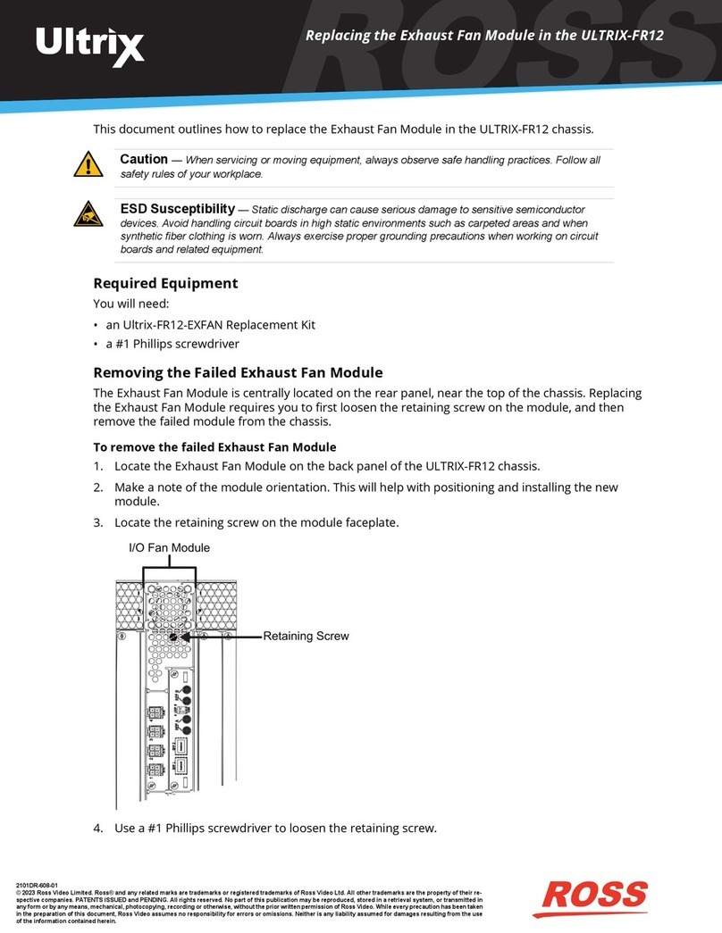
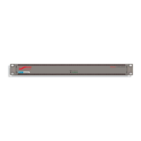
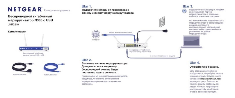
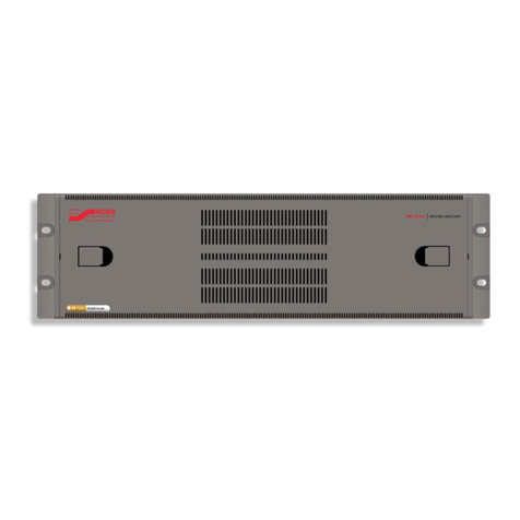
Ross ULTRIX-FR12 User manual

Printed in Canada. © 2023 Ross Video Limited. Ross®, and any related marks are trademarks or registered trademarks of Ross Video Limited. All other trademarks are the property of their respective companies.
PATENTS ISSUED and PENDING. All rights reserved. No part of this publication may be reproduced, stored in a retrieval system, or transmitted in any form or by any means, mechanical, photocopying, recording
or otherwise, without the prior written permission of Ross Video. While every precaution has been taken in the preparation of this document, Ross Video assumes no responsibility for errors or omissions. Neither is
any liability assumed for damages resulting from the use of the information contained herein.
2101DR-602-02
Page 1
1 4 1 41 4 1 4
ENET 1 ENET 2
ALARMLTC micro SD
R-OUT
SFP 1 SFP 2 LOOP
TERM
A B
2 3 4 5 6 7 8 91 10 11 13 14 15 1612
1
C DA B
Ultrix HDX-IO !REF A B
9 10 11 12 13 14 15 16
OUT
5 6 7 81 32 4 9 10 11 12 13 14 15 16
IN
5 6 7 832 4
C DA B
Ultrix HDX-IO !REF A B
9 10 11 12 13 14 15 16
OUT
5 6 7 81 32 4 9 10 11 12 13 14 15 16
IN
5 6 7 832 4
C DA B
Ultrix HDX-IO !REF A B
9 10 11 12 13 14 15 16
OUT
5 6 7 81 32 4 9 10 11 12 13 14 15 16
IN
5 6 7 832 4
C DA B
Ultrix HDX-IO !REF A B
9 10 11 12 13 14 15 16
OUT
5 6 7 81 32 4 9 10 11 12 13 14 15 16
IN
5 6 7 832 4
C DA B
Ultrix HDX-IO !REF A B
9 10 11 12 13 14 15 16
OUT
5 6 7 81 32 4 9 10 11 12 13 14 15 16
IN
5 6 7 832 4
C DA B
Ultrix HDX-IO !REF A B
9 10 11 12 13 14 15 16
OUT
5 6 7 81 32 4 9 10 11 12 13 14 15 16
IN
5 6 7 832 4
C DA B
Ultrix HDX-IO !REF A B
9 10 11 12 13 14 15 16
OUT
5 6 7 81 32 4 9 10 11 12 13 14 15 16
IN
5 6 7 832 4
C DA B
Ultrix HDX-IO !REF A B
9 10 11 12 13 14 15 16
OUT
5 6 7 81 32 4 9 10 11 12 13 14 15 16
IN
5 6 7 832 4
C DA B
Ultrix HDX-IO !REF A B
9 10 11 12 13 14 15 16
OUT
5 6 7 81 32 4 9 10 11 12 13 14 15 16
IN
5 6 7 832 4
C DA B
Ultrix HDX-IO !REF A B
9 10 11 12 13 14 15 16
OUT
5 6 7 81 32 4 9 10 11 12 13 14 15 16
IN
5 6 7 832 4
C DA B
Ultrix HDX-IO !REF A B
9 10 11 12 13 14 15 16
OUT
5 6 7 81 32 4 9 10 11 12 13 14 15 16
IN
5 6 7 832 4
C DA B
Ultrix HDX-IO !REF A B
9 10 11 12 13 14 15 16
OUT
5 6 7 81 32 4 9 10 11 12 13 14 15 16
IN
5 6 7 832 4
C DA B
Ultrix HDX-IO !REF A B
9 10 11 12 13 14 15 16
OUT
5 6 7 81 32 4 9 10 11 12 13 14 15 16
IN
5 6 7 832 4
C DA B
Ultrix HDX-IO !REF A B
9 10 11 12 13 14 15 16
OUT
5 6 7 81 32 4 9 10 11 12 13 14 15 16
IN
5 6 7 832 4
C DA B
Ultrix HDX-IO !REF A B
9 10 11 12 13 14 15 16
OUT
5 6 7 81 32 4 9 10 11 12 13 14 15 16
IN
5 6 7 832 4
C DA B
Ultrix HDX-IO !REF A B
9 10 11 12 13 14 15 16
OUT
5 6 7 81 32 4 9 10 11 12 13 14 15 16
IN
5 6 7 832 4
Reference Cabling
3Connect a 75ohm coaxial cable with
HD-BNC connectors between the video
reference signal output and the REF A
connector on the router.
Connect a 75ohm coaxial cable with
HD-BNC connectors to the next device in
the system or terminate, set the LOOP DIP
SWITCH to TERM if end of reference link.
3a
3b
1GbE Network Cabling
2Note: The router must be connected to the same
network as the other devices in your routing system.
Plug an Ethernet cable from your network into
the ENET 1 port. This is the primary network
connection for the router.
Plug an Ethernet cable from your network into
the ENET 2 port. This is the backup network
connection for the router. (optional)
2a
2b
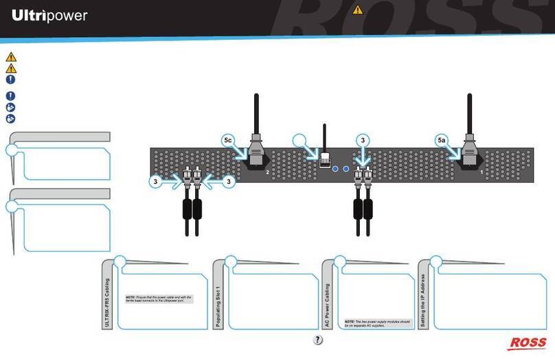
Read the user documentation for your Ultripower and ULTRIX-FR12
before starting work or operating equipment.
CAUTION: Risk of electrical shock. Enclosure shall be connected
to earth ground via protective earth stud and 12AWG conductor or
larger.
WARNING: When servicing or moving equipment, always observe
safe handling practices. Get help to move heavy items. Use safe
lifting techniques. Follow all safety rules of your workplace.
CAUTION: The ULTRIX-FR12 weighs approximately 122lbs
(55.34kg). Two people should work together to lift it into place to
avoid physical injury.
Source Cabling
4Connect a 75ohm coaxial cable with
HD-BNC connectors between the source
device and the input connector on the rear
panel of the router.
Ensure the bayonnet connector is locked in
place correctly.
4a
4b
Destination Cabling
5Connect a 75ohm coaxial cable with
HD-BNC connectors between the
destination device and the output connector
on the rear panel of the router.
Ensure the bayonnet connector is locked in
place correctly.
5a
5b
Have a question? Call our free, 24-hour technical support hotline to
speak with a live product specialist located right here in our facility.
Tel: (+1) 844 • 652 • 0645
Email: [email protected]
Rack Mounting
1
CAUTION: Adequate ventilation within a rack frame must be maintained. Ensure side to side ventilation is not
compromised. Refer to the ULTRIX-FR12 Installation Guide for more information.
The ULTRIX-FR12 router is designed for installation into a standard 19” equipment rack. It has integrated rack ears, allowing it to be
screwed in using standard screws and cage nuts. It is recommended to use M6 x 10mm screws with 40in-lbs [4.5N·m] of torque.
Before working on any rack, ensure that it is stable. Make sure that any rack is level and stable before extending a component from the
rack.
Always load the rack from the bottom up, and load the heaviest item in the rack first.
Under some conditions, the ambient air temperature inside rack-mount cabinets can be greater than the ambient temperatures within a
room. For safe long term reliability, ensure the ambient air temperatures at the router intake are within the router’s specified operating
temperature range. Adequate ventilation within a rack frame must also be maintained.
The ULTRIX-FR12 mounts in the rack frame by means of rack screws fastened through the front and back mounting ears. This should
normally be sufficient to carry the load, including the weight of accompanying cables. There are 4 slots in each rack ear which need to
be populated with a total of 8 screws.
After installing equipment/components within a rack, never pull more than one component out of the rack on its slide assemblies at one
time. The weight of more than one extended component could cause the rack to tip over and may result in serious injury.
NOTICE: The ULTRIX-FR12 frame does not have a power
switch. Ensure that the Ultripower is not connected to mains
power before connecting the power cables from the Ultripower to
the other components. If the Ultripower is energized as you
connect the power cables to the ULTRIX-FR12, the system could
start to power up before it has enough power to operate and
could damage the equipment.
Protective
Earth
Ground
2b
2a
3a
3b
Installing and Cabling the ULTRIX-FR12 Router CAUTION
Before you set up and operate your router, refer to the “Important Regulatory and Safety Notices to
Service Personnel” document that was included with your router. It is also recommended to refer
to the Ultrix Installation Guide which is available for download from our website.
Have a question? Call our free,
24-hour technical support hotline to
speak with a live product specialist
located right here in our facility.
Tel: (+1) 844 • 652 • 0645
Email: [email protected]
Page 2
1 4 1 41 4 1 4
ENET 1 ENET 2
ALARMLTC micro SD
R-OUT
SFP 1 SFP 2 LOOP
TERM
A B
2 3 4 5 6 7 8 91 10 11 13 14 15 1612
1
C DA B
Ultrix HDX-IO !REF A B
9 10 11 12 13 14 15 16
OUT
5 6 7 81 32 4 9 10 11 12 13 14 15 16
IN
5 6 7 832 4
C DA B
Ultrix HDX-IO !REF A B
9 10 11 12 13 14 15 16
OUT
5 6 7 81 32 4 9 10 11 12 13 14 15 16
IN
5 6 7 832 4
C DA B
Ultrix HDX-IO !REF A B
9 10 11 12 13 14 15 16
OUT
5 6 7 81 32 4 9 10 11 12 13 14 15 16
IN
5 6 7 832 4
C DA B
Ultrix HDX-IO !REF A B
9 10 11 12 13 14 15 16
OUT
5 6 7 81 32 4 9 10 11 12 13 14 15 16
IN
5 6 7 832 4
C DA B
Ultrix HDX-IO !REF A B
9 10 11 12 13 14 15 16
OUT
5 6 7 81 32 4 9 10 11 12 13 14 15 16
IN
5 6 7 832 4
C DA B
Ultrix HDX-IO !REF A B
9 10 11 12 13 14 15 16
OUT
5 6 7 81 32 4 9 10 11 12 13 14 15 16
IN
5 6 7 832 4
C DA B
Ultrix HDX-IO !REF A B
9 10 11 12 13 14 15 16
OUT
5 6 7 81 32 4 9 10 11 12 13 14 15 16
IN
5 6 7 832 4
C DA B
Ultrix HDX-IO !REF A B
9 10 11 12 13 14 15 16
OUT
5 6 7 81 32 4 9 10 11 12 13 14 15 16
IN
5 6 7 832 4
C DA B
Ultrix HDX-IO !REF A B
9 10 11 12 13 14 15 16
OUT
5 6 7 81 32 4 9 10 11 12 13 14 15 16
IN
5 6 7 832 4
C DA B
Ultrix HDX-IO !REF A B
9 10 11 12 13 14 15 16
OUT
5 6 7 81 32 4 9 10 11 12 13 14 15 16
IN
5 6 7 832 4
C DA B
Ultrix HDX-IO !REF A B
9 10 11 12 13 14 15 16
OUT
5 6 7 81 32 4 9 10 11 12 13 14 15 16
IN
5 6 7 832 4
C DA B
Ultrix HDX-IO !REF A B
9 10 11 12 13 14 15 16
OUT
5 6 7 81 32 4 9 10 11 12 13 14 15 16
IN
5 6 7 832 4
C DA B
Ultrix HDX-IO !REF A B
9 10 11 12 13 14 15 16
OUT
5 6 7 81 32 4 9 10 11 12 13 14 15 16
IN
5 6 7 832 4
C DA B
Ultrix HDX-IO !REF A B
9 10 11 12 13 14 15 16
OUT
5 6 7 81 32 4 9 10 11 12 13 14 15 16
IN
5 6 7 832 4
C DA B
Ultrix HDX-IO !REF A B
9 10 11 12 13 14 15 16
OUT
5 6 7 81 32 4 9 10 11 12 13 14 15 16
IN
5 6 7 832 4
C DA B
Ultrix HDX-IO !REF A B
9 10 11 12 13 14 15 16
OUT
5 6 7 81 32 4 9 10 11 12 13 14 15 16
IN
5 6 7 832 4
CAUTION: Risk of electrical shock. Enclosure shall be connected to earth ground via protective earth stud and 12AWG conductor or larger.
Read the user documentation for your Ultripowers and ULTRIX-FR12 before starting work or operating equipment.
NOTICE: The ULTRIX-FR12 frame does not have a power switch. Ensure that each Ultripower is not connected to mains power before
connecting the power cables from an Ultripower to the other components. If an Ultripower is energized as you connect the power cables to
the ULTRIX-FR12, the system could start to power up before it has enough power to operate and could damage the equipment.
Powering on the ULTRIX-FR12
6
To verify that each Ultripower Output state is toggled to OFF
6a Locate the Ultricore BCS node in the Tree View of DashBoard.
6b Expand the main Ultricore BCS node.
6c Expand the Ultricore BCS sub-node to display a list of sub-nodes in the Tree View.
6d Expand the Devices sub-node.
6e Double-click the Ultripower Manager sub-node.
6f From the Group list, select the required Ultripower group.
6g Click OFF.
6h Verify that each Ultripower is the same state (Off). Refer to the Ultripower User Guide for details.
To cable two Ultripowers to the ULTRIX-FR12
6i Connect all four power cables from the ULTRIX-FR12 to the matching power connectors on the first Ultripower chassis.
6j Connect all four power cables from the ULTRIX-FR12 to the matching power connectors on the second Ultripower chassis.
To cable additional Ultripowers (optional)
Note: This procedure is only required when installing a high power redundancy setup.
6k Connect all four power cables from the ULTRIX-FR12 to the matching power connectors on the third Ultripower chassis.
6l Connect all four power cables from the ULTRIX-FR12 to the matching power connectors on the fourth Ultripower chassis.
To toggle the Ultripower Group to ON
6m Locate the Ultricore BCS node in the Tree View of DashBoard.
6n Expand the main Ultricore BCS node.
6o Expand the Ultricore BCS sub-node to display a list of sub-nodes in the Tree View.
6p Expand the Devices sub-node.
6q Double-click the Ultripower Manager sub-node.
6r Click ON.
NOTICE: The Output state of the grouped Ultripowers must be toggled to OFF before connecting to the ULTRIX-FR12.
CAUTION: Before setting an Ultripower Group to ON, ensure its Ultripower PSU average power output is below 5W.
Before You Begin
!The ULTRIX-FR12 requires multiple Ultripower power supply units (minimum of two). It is required that these power cycle together.
The Ultricore BCS has a feature to group up to 4 Ultripower units. When the Ultripower group output state is toggled, the output of the
units in that group is set to the same state.
NOTICE: The Ultripower units must be configured prior to connecting the power connections to the ULTRIX-FR12 chassis.
To set up Ultripower grouping
Note: Do not connect the Ultripower units to the ULTRIX-FR12 until the Ultripower units are configured and grouped.
1. Connect each Ultripower unit to mains AC and your facility network.
2. Configure Ultripower network IP addresses via DashBoard > Walkabout. Refer to the Ultripower User Guide for details.
3. Change the names of the Ultripower units (particularly the primary) for easy identification in the DashBoard Device Tree.
4. Add the Ultripower units to the DashBoard Device Tree. Refer to the Ultripower User Guide for details.
5. For each Ultripower, navigate to the Setup tab and ensure the output ports are grouped together.
6. In DashBoard, Locate the Ultricore BCS node in the Tree View of DashBoard.
7. Expand the main Ultricore BCS node.
8. Expand the Ultricore BCS sub-node to display a list of sub-nodes in the Tree View.
9. Expand the Devices sub-node.
10. Double-click the Ultripower Manager sub-node.
11.Click Add under the Group pane. The Group pane displays a new entry “New Group”.
12.To assign a unique identifier for the group, click “New Group” and edit as required.
13.Select the group from the list in the Group pane.
14.Click Add under the Ultripower pane to open the Select Ultripower dialog.
15.From the drop-down menu, expand the node for the Ultripower unit to include in this group.
16.Double-click the sub-node.
17.Verify that the information is correct.
18.Click OK. The Select Ultripower dialog closes and the Ultripower pane updates to list the selected unit.
19.Repeat steps 11 to 18 to add the second Ultripower unit to the group.
Note: If you are setting up a redundant system or a high-powered system, you will need to include 4 Ultripower units to the group.
20. Click OFF.
Protective
Earth
Ground
6l
6k
6j
6i
Powering the ULTRIX-FR12 Router CAUTION
Before you set up and operate your router, refer to the “Important Regulatory and Safety Notices to
Service Personnel” document that was included with your router. It is also recommended to refer
to the Ultrix Installation Guide which is available for download from our website.
Table of contents
Other Ross Network Router manuals

Ross
Ross ULTRIX-FR12 User manual

Ross
Ross ULTRIX-FR12 User manual

Ross
Ross ULTRIX-FR12 User manual

Ross
Ross NK-16 User manual

Ross
Ross NK Series Operating and safety instructions

Ross
Ross ULTRIX-MODX-IO User manual

Ross
Ross NK-3RD User manual

Ross
Ross ULTRIX-FR12 User manual

Ross
Ross NK-RP1 Series User manual